EP1046883A2 - Schwingungs-Gyroskop - Google Patents
Schwingungs-Gyroskop Download PDFInfo
- Publication number
- EP1046883A2 EP1046883A2 EP00107687A EP00107687A EP1046883A2 EP 1046883 A2 EP1046883 A2 EP 1046883A2 EP 00107687 A EP00107687 A EP 00107687A EP 00107687 A EP00107687 A EP 00107687A EP 1046883 A2 EP1046883 A2 EP 1046883A2
- Authority
- EP
- European Patent Office
- Prior art keywords
- vibrating
- electrodes
- detecting
- exciting
- vibrating gyroscope
- Prior art date
- Legal status (The legal status is an assumption and is not a legal conclusion. Google has not performed a legal analysis and makes no representation as to the accuracy of the status listed.)
- Withdrawn
Links
- 238000005452 bending Methods 0.000 claims abstract description 22
- 238000006073 displacement reaction Methods 0.000 claims abstract description 6
- 239000000758 substrate Substances 0.000 claims description 27
- 238000001514 detection method Methods 0.000 claims description 14
- 239000002184 metal Substances 0.000 claims description 5
- 230000010355 oscillation Effects 0.000 claims description 4
- 230000002093 peripheral effect Effects 0.000 description 7
- 239000000463 material Substances 0.000 description 6
- 230000001360 synchronised effect Effects 0.000 description 5
- 238000009499 grossing Methods 0.000 description 4
- 230000035945 sensitivity Effects 0.000 description 3
- 238000007796 conventional method Methods 0.000 description 2
- 230000008878 coupling Effects 0.000 description 2
- 238000010168 coupling process Methods 0.000 description 2
- 238000005859 coupling reaction Methods 0.000 description 2
- 238000005259 measurement Methods 0.000 description 2
- 238000000034 method Methods 0.000 description 2
- 239000004020 conductor Substances 0.000 description 1
- 230000007850 degeneration Effects 0.000 description 1
- 239000013013 elastic material Substances 0.000 description 1
- 230000002708 enhancing effect Effects 0.000 description 1
- 238000005530 etching Methods 0.000 description 1
- 239000011159 matrix material Substances 0.000 description 1
- 239000007769 metal material Substances 0.000 description 1
- 210000003254 palate Anatomy 0.000 description 1
- 230000002265 prevention Effects 0.000 description 1
Images



Classifications
-
- G—PHYSICS
- G01—MEASURING; TESTING
- G01C—MEASURING DISTANCES, LEVELS OR BEARINGS; SURVEYING; NAVIGATION; GYROSCOPIC INSTRUMENTS; PHOTOGRAMMETRY OR VIDEOGRAMMETRY
- G01C19/00—Gyroscopes; Turn-sensitive devices using vibrating masses; Turn-sensitive devices without moving masses; Measuring angular rate using gyroscopic effects
-
- G—PHYSICS
- G01—MEASURING; TESTING
- G01C—MEASURING DISTANCES, LEVELS OR BEARINGS; SURVEYING; NAVIGATION; GYROSCOPIC INSTRUMENTS; PHOTOGRAMMETRY OR VIDEOGRAMMETRY
- G01C19/00—Gyroscopes; Turn-sensitive devices using vibrating masses; Turn-sensitive devices without moving masses; Measuring angular rate using gyroscopic effects
- G01C19/56—Turn-sensitive devices using vibrating masses, e.g. vibratory angular rate sensors based on Coriolis forces
- G01C19/5719—Turn-sensitive devices using vibrating masses, e.g. vibratory angular rate sensors based on Coriolis forces using planar vibrating masses driven in a translation vibration along an axis
Definitions
- the present invention relates to a vibrating gyroscope, and more particularly to a vibrating gyroscope used, for example, to detect angular velocities for prevention of camera shake.
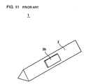
- FIG. 11 is a perspective view of an example of a conventional vibrating gyroscope.
- a vibrating gyroscope 1 includes a vibrating body 2 in, for example, the shape of a regular triangle. As seen in FIGs. 11 and 12, three peripheral surfaces of the vibrating body 2 have piezoelectric elements 3a, 3b, and 3c, respectively.
- a vibration circuit 4 is connected between the piezoelectric elements 3a and 3b and the piezoelectric element 3c.
- the piezoelectric elements 3a and 3b are connected to a detection circuit 5.
- the detection circuit 5 includes, for example, a differential circuit, a synchronous detection circuit, a smoothing circuit, and a DC amplifying circuit.
- a signal outputted from the piezoelectric element 3c is returned to the vibration circuit 4.
- the vibration circuit 4 amplifies the returned signal and compensates the amplified signal in phase, thereby forming an exciting signal.
- the exciting signal thus obtained is fed to the piezoelectric elements 3a and 3b.
- This causes the vibrating body 2 to perform bending vibrations in the direction perpendicular to the surface where the piezoelectric element 3c is formed. In this state, bending states of the piezoelectric elements 3a and 3b are the same, and signals outputted therefrom are also the same. Therefore, no signal is outputted from the differential circuit in the detection circuit 5.
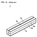
- a vibrating body 2 may be manufactured by coupling two piezoelectric substrates 6a and 6b. As indicated by arrows in FIG. 13, the piezoelectric substrates are polarized so as to oppose each other. In this case, electrodes 7a and 7b each extending in the length direction are formed on one of opposing surfaces of the vibrating body 2, and an electrode 8 is formed on the entire surface of the other opposing surfaces thereof.
- the described vibrating gyroscope 1 also allows the angular velocity to be detected.
- the present invention is directed to a vibrating gyroscope that satisfies this need.
- the vibrating gyroscope comprises two planar vibrating plates arranged to oppose each other.
- the two vibrating plates vibrate under buckling vibration mode and a second-order bending vibration mode which is degenerated with or close to the buckling vibration mode.
- the vibrating gyroscope detects Coriolis force by detecting displacements in amplitude balance of the second-order bending vibration modes generated when an angular rotation velocity around an axis parallel to surfaces of the vibrating plates is applied.
- the described vibrating gyroscope may comprise an intermediate member formed between the two vibrating plates to form a spaced section between the two vibrating plates, and a plurality of exciting and detecting elements formed on the vibrating plates to vibrate the vibrating plates and to output signals generated by vibrations of the' vibrating plates, wherein a first detecting section is formed according to a combination for the two adjacent exciting and detecting elements, a second detecting section is formed according to another combination for the two adjacent exciting and detecting elements, and the first detecting section and the second detecting section are arranged perpendicular to each other.
- the exciting and detecting elements are not formed in positions opposing to the intermediate member, and are formed in positions opposing to the spaced section.
- the individual exciting and detecting elements are formed of piezoelectric substrates, and electrodes sectioned crosswise into four are formed on the piezoelectric substrates, whereby the electrodes and the piezoelectric substrates may be used to form the exciting and detecting elements.
- the vibrating plate may be formed of a metal plate, and piezoelectric elements sectioned crosswise into four and formed on the vibrating plate may be used to form the exciting and detecting element.
- the intermediate member may be formed of a frame member in which a through opening is formed in its central portion.
- the intermediate member may be formed of multiple members arranged on multiple end portions of the vibrating plates.
- buckling vibration is generated such that the amplitude of each of central portions of the vibrating reaches the maximum.
- the Coriolis force varies vibration of the vibrating plate in the quadratic bending vibration mode.
- the buckling vibration and the vibration in the quadratic bending vibration mode are either degenerated or arranged similar, a point where the amplitude of the vibrating plate reaches the maximum vibrates deviating from the central portion of the vibrating plate.
- the difference is caused between bending states of two exciting and detecting elements constituting one of the first and second detecting sections, and a signal corresponding to the Coriolis force is outputted from one of the first and second detecting sections. Since the first and second detecting sections are arranged perpendicular to each other, signals corresponding to angular velocities about respect to two directions that are perpendicular to each other can be obtained.
- the exciting and detecting elements are preferably arranged at positions opposing the spaced section. This arrangement is made to cause the buckling vibration so that the amplitude at the central portion of the vibrating plate reaches the maximum.
- the piezoelectric substrate may be used for the vibrating plate, and the piezoelectric substrates and the electrodes sectioned crosswise into four thereon may be used to form the exciting and detecting element.
- the metal plate may be used for each of the vibrating plates.
- the exciting and detecting element is formed by the four piezoelectric elements sectioned crosswise and formed on the vibrating plate.
- the intermediate member is provided to form the spaced section between the vibrating plates opposing each other. Therefore, the intermediate member may be formed of either the frame member in which the through-opening is formed or the multiple members arranged at the multiple end portions of the vibrating plates.
- angular velocities with axes in two directions can be detected by a single vibrating gyroscope. Furthermore, since the vibrating gyroscope can be excited with a single vibration, cost reduction can be implemented, compared to conventional methods each using two vibrating gyroscopes.
- FIG. 1 is a perspective view showing an example of a vibrating gyroscope of the present invention.
- FIG. 2 is a perspective view taken at a different angle of the vibrating gyroscope shown in FIG. 1; and
- FIG. 3 is an exploded perspective view thereof.
- a vibrating gyroscope 10 includes an intermediate member 12. As shown in FIG. 3, the intermediate member 12 is formed in a frame shape having a through opening in its central portion.
- a vibrating plate 14 is formed on one of the opposing sides of the intermediate member 12.
- the vibrating plate 14 is formed, for example, by coupling piezoelectric substrates 16 and 18. As indicated by arrows in FIG. 3, the piezoelectric substrates 16 and 18 are polarized so as to oppose each other in the thickness direction.
- the piezoelectric substrate 16 there are formed 16 sectional electrodes, of which four electrodes 20a, 20b, 20c, and 20d are used to allow input and/or output of signals. These electrodes are formed by cutting a planar electrode by a dicer in a matrix. This forms the electrodes 20a, 20b, 20c, and 20d into crosswise sections. In the vibrating gyroscope 10, since the electrodes are formed in the manner described above, 16 electrodes are formed. However, the electrodes 20a, 20b, 20c, and 20d are required for the vibrating gyroscope 10, but other peripheral electrodes are not required.
- the peripheral electrodes need not be formed.
- the peripheral electrodes may be similarly eliminated.
- a planar electrode 22 is formed on the piezoelectric substrate 18. These piezoelectric substrates 16 and 18, the electrodes 20a, 20b, 20c, and 20d, and planar electrode 22 form an exciting and detecting element.
- the vibrating plate 24 is formed on the other one of the opposing sides of the intermediate member 12.
- the vibrating plate 24 has a structure similar to that of the vibrating plate 14.
- the vibrating plate 24 includes piezoelectric substrates 26 and 28 that are coupled, and the piezoelectric substrates 26 and 28 are polarized so as to oppose each other.
- the piezoelectric substrate 26 there are formed 16 sectional electrodes, of which electrodes 30a, 30b, 30c, and 30d in a central portion are used to allow input and/or output of signals.
- a planar electrode 32 is formed on the piezoelectric substrate 28.
- the piezoelectric substrates 26 and 28, the electrodes 30a, 30b, 30c, and 30d, and planar electrode 32 form an exciting and detecting element.
- the two vibrating plates 14 and 24 are arranged in such a manner as to sandwich the intermediate member 12; accordingly, a spaced section is formed between the vibrating plates 14 and 24.
- the electrodes 20a, 20b, 20c, and 20d and the electrodes 30a, 30b, 30c, and 30d that constitute the exciting and detecting elements are arranged in positions opposing the spaced section. This arrangement allows the vibrating plates 14 and 24 to efficiently perform buckling vibrations in response to exciting signals.
- FIG. 4 shows only the electrodes 20a, 20b, 20c, and 20d, the electrodes 30a, 30b, 30c, planar electrodes 22 and 32, and the intermediate member 12 to show the relationship in connection between the individual electrodes and the circuits in the vibrating gyroscope 10.
- the individual planar electrodes 22 and 32 and the intermediate member 12 are shown in the same outline dimensions of those of each of the electrodes 20a, 20b, 20c, and 20d. Actually, however, they have the same outline dimensions as those of the vibrating plates 14 and 24, as shown in FIG. 1.
- the electrodes 20a, 20b, 20c, and 20d are connected to resistors 40a, 40b, 40c, and 40d, respectively.
- the electrodes 30a, 30b, 30c, and 30d are connected to resistors 42a, 42b, 42c, and 42d, respectively.
- a oscillation circuit 44 is formed between the resistors 40a, 40b, 40c, and 40d and the resistors 42a, 42b, 42c, and 42d.
- a conductive material is applied onto partial areas or the entire area of the intermediate member 12.
- the intermediate member 12 is electrically connected to the planar electrodes 22 and 32; thereby, the planar electrodes 22 and 32 are connected to the oscillation circuit 44 via the intermediate member 12.
- a material for the intermediate member 12 a material similar to a material for the vibrating plates 14 and 24 is preferable so as not to disturb vibrations of the vibrating plates 14 and 24.
- the intermediate member 12 can be formed by using the same material as that for the piezoelectric substrate 16, 18, 26, and 28, and by forming an electrode layer over the material.
- the planar electrodes 22 and 32 are electrically connected to the electrode layer.
- a high-elastic material may be used to form the intermediate member 12.
- the two electrodes 20b and 20d that are adjacent to the side of the vibrating plate 14 are connected to a differential circuit 46.
- a signal outputted from the differential circuit 46 is detected in a synchronous detection circuit 48 in synchronization with, for example, a signal outputted from the vibration circuit 44.
- the signal detected in the synchronous detection circuit 48 is then smoothed in a smoothing circuit 50, and subsequently, is amplified in a DC amplifying circuit 52.
- the two electrodes 30c and 30d that are adjacent to each other on the side of the vibrating plate 24 are connected to a differential circuit 54.
- a signal outputted from the differential circuit 54 is detected in a synchronous detection circuit 56 in synchronization with, for example, a signal outputted from the vibration circuit 44.
- the signal detected in the synchronization detector circuit 56 is then smoothed in a smoother circuit 58, and subsequently, is amplified in a DC amplifying circuit 60.
- the two electrodes 20b and 20d that are adjacent to each other form a first detecting section; and the two electrodes 30c and 30d that are adjacent to each other form a second detecting section.
- each of these first detecting section and second detecting section may be a combination of optional two electrodes that are adjacent to each other, electrodes constituting each of the first detecting section and the second detecting section must be selected to be those perpendicular to each other. Accordingly, when the electrodes 20b and 20d are selected for the first detecting section, the electrodes 30a and 30b may be selected as the second detecting section. Alternatively, an arrangement may be such that the electrodes 20c and 20d are selected, and the electrode 20d is shared by the first detecting section and the second detecting section.
- the signals outputted from the planar electrode 22 and 32 are fed back to the vibration circuit 44.
- the feedback signals are amplified in the vibration circuit 44, and also, are compensated in phase, thereby forming exciting signals.
- These exciting signals are fed to the electrodes 20a, 20b, 20c, and 20d and the electrodes 30a, 30b, 30c, and 30d.
- the vibrating plates 14 and 24 vibrate under a buckling vibration mode in the opposing direction with each other such that each of the vibrating plates 14 and 24 vibrates, producing the maximum amplitude at its central portion.
- the dotted line N indicates the node of vibration in FIG. 5A.
- a second-order bending vibration as shown in FIGs. 6A and 6B is also excited, and that the second-order bending vibration and the buckling vibration as explained above are degenerated so that detection sensitivity of the vibration gyroscope becomes the maximum.
- another second-order bending vibration which is perpendicular to the second-order bending vibration mode shown in FIG. 6A is also excited.
- the buckling vibration mode and the second-order bending vibration mode can be degenerated by optimizing plate thicknesses, areas (outer dimensions), and the inner dimensions of the spaced section.
- the sufficient high sensitivity can be obtained if the two vibration modes are close with each other, i.e., if the difference of resonance frequencies of the two vibration mode is within about 1% of the resonance frequency.
- the described vibrations cause identical vibration states at portions of the piezoelectric substrates 16 and 18 where the electrodes 20a, 20b, 20c, and 20d are formed, causing signals outputted from the electrodes 20a, 20b, 20c, and 20d to be the same. Therefore, no signal is outputted from the differential circuit 54. This proves that no angular velocity is applied to the vibrating gyroscope 10.
- Displacement in the vibration states of the piezoelectric substrates 16 and 18 corresponds to the magnitude of the Coriolis force, so that variations in the signals outputted from the electrodes 20b and 20d correspond to Coriolis forces.
- the aforementioned difference between the signals is outputted from the differential circuit 46. Since the signals outputted from the electrodes 20b and 20d correspond to Coriolis forces, large-level signals corresponding to variations, that is, Coriolis forces, can be obtained from the differential circuit 46. Each of the signals outputted from the differential circuit 46 is detected in synchronization with the signal outputted from the vibration circuit 44. According to this, only one of the positive side and the negative side of the output signal or a signal of which the positive side or the negative side is inverted is detected. The detected signal is smoothed in the smoothing circuit 50, and also, is amplified in the DC amplifying circuit 52.
- the level of the signal outputted from the DC amplifying circuit 52 also corresponds to the Coriolis force.
- the frequency of angular velocity can be detected according to the level of the signal outputted from the DC amplifying circuit 52.
- the polarity of a signal detected in the synchronous detection circuit 48 is also reversed. Accordingly, the polarity of the signal outputted from the DC amplifying circuit 52 is also reversed. The polarity of the signal outputted from the DC amplifying circuit 52 serves to detect the direction of the angular velocity.
- the Coriolis force is exerted in the direction opposing the vibrating plate 14 at the time, displacing vibration of the vibrating plate 24.
- the vibration state varies in two sides of an axis extending between the electrodes 30b and 30d, signals outputted from the electrodes 30c and 30d also vary. Therefore, no signal is outputted from the differential circuit 54.
- vibration states of the piezoelectric substrates 26 and 28 vary corresponding to Coriolis forces on the two sides of the axis. This causes the difference between signals outputted from the electrodes 30c and 30d, thereby causing the differential circuit 54 to detect the signal outputted from the differential circuit 54.
- the signal is smoothed in the smoother circuit 58, and subsequently, is amplified in the DC amplifying circuit 60, thereby allowing detection of an angular velocity about the axis extending between the electrodes 30c and 30d in the center.
- the piezoelectric substrates 16 and 18 formed in areas where the electrodes 20b and 20d on the side of the vibrating plate 14 also displace similarly to the above. Therefore, no signal is outputted from the differential circuit 46.
- the angular velocity about the axis extending between the electrodes 20b and 20d in the center can be detected.
- the angular velocity about the axis extending between the electrodes 30a, 30b, 30c, and 30d in the center can be detected. That is, according to the arrangement in which the first detecting section composed of the electrodes 20b and 20d is perpendicular to the second detecting section composed of the electrodes 30c and 30d, the angular velocity about each of the two axes perpendicular to each other in the center can be detected.
- the vibrating plates 14 and 24 can be excited to cause vibrations. Compared to conventional methods each using two oscillation circuits, the above-described method allows cost reduction to be implemented.
- each of the vibrating plates 14 and 24 may be in the shape of a circular disc.
- an intermediate member 12 is formed in the shape of a ring.
- each of electrodes 20a, 20b, 20c, and 20d on the side of a vibrating plate 14, and each of electrodes 30a, 30b, 30c, and 30d on the side of a vibrating plate 24 is formed in the shape of an arcuate sector.
- peripheral electrodes around the electrodes 20a, 20b, 20c, and 20d, and peripheral electrodes around the electrodes 30a, 30b, 30c, and 30d do not work for operation of a vibrating gyroscope 10, so that they may be eliminated.
- the vibrating gyroscope 10 as described above is also capable of detecting the angular velocity with each of the two axes perpendicular each other by using the circuits shown in FIG. 4.
- the intermediate member 12 need not be formed of a frame material having a through opening in its central portion, and may be formed at each of the four corners of the vibrating plates 14 and 24. Thus, all that is essentially required is a spaced section formed corresponding to the area where the electrodes 20a, 20b, 20c, and 20d and the electrodes 30a, 30b, 30c, and 30d that are used to allow input and/or output of signals. Therefore, the shape of the intermediate member 12 for forming the spaced section may be changed as required.
- electrodes constituting each exciting and detecting element may be two sectional electrodes. Electrodes 62a and 62b formed on the side of a vibrating plate 14 and electrodes 64a and 64b formed on the side of a vibrating plate 24 are arranged perpendicular to each other. In this case, using the circuits shown in FIG. 10 allows intermediate member 12 to be excited, and also, allows detection of a signal corresponding to the angular velocity with respect to each of axes perpendicular to each other. In the described arrangement of the electrodes, as in the other cases, the electrodes 62a and 62b and the electrodes 64a and 64b are preferably formed in positions corresponding to a spaced section where the intermediate member 12 does not exist.
- piezoelectric elements each having electrodes on two surfaces of a piezoelectric layer may be used.
- the piezoelectric elements are arranged similarly either to the electrodes 20a, 20b, 20c, and 20d and the electrodes 30a, 30b, 30c, and 30d shown in FIG. 1 or to the electrodes 62a and 62b and the electrodes 64a and 64b shown in FIG. 10.
- no piezoelectric elements need be formed in positions corresponding to peripheral electrodes around the aforementioned electrodes.
- an intermediate member 12 may be formed of the same metal material as used for the vibrating plates 14 and 24.
- the intermediate member 12 thus formed is connected to a vibration circuit 44, thereby allowing connection of the electrodes on one of the sides of each of the piezoelectric elements to the vibration circuit 44.
Landscapes
- Physics & Mathematics (AREA)
- Engineering & Computer Science (AREA)
- General Physics & Mathematics (AREA)
- Radar, Positioning & Navigation (AREA)
- Remote Sensing (AREA)
- Gyroscopes (AREA)
Applications Claiming Priority (2)
| Application Number | Priority Date | Filing Date | Title |
|---|---|---|---|
| JP11474499A JP3407689B2 (ja) | 1999-04-22 | 1999-04-22 | 振動ジャイロ |
| JP11474499 | 1999-04-22 |
Publications (2)
| Publication Number | Publication Date |
|---|---|
| EP1046883A2 true EP1046883A2 (de) | 2000-10-25 |
| EP1046883A3 EP1046883A3 (de) | 2001-05-30 |
Family
ID=14645586
Family Applications (1)
| Application Number | Title | Priority Date | Filing Date |
|---|---|---|---|
| EP00107687A Withdrawn EP1046883A3 (de) | 1999-04-22 | 2000-04-10 | Schwingungs-Gyroskop |
Country Status (5)
| Country | Link |
|---|---|
| US (1) | US6281618B1 (de) |
| EP (1) | EP1046883A3 (de) |
| JP (1) | JP3407689B2 (de) |
| KR (1) | KR100364968B1 (de) |
| CN (1) | CN1174221C (de) |
Cited By (1)
| Publication number | Priority date | Publication date | Assignee | Title |
|---|---|---|---|---|
| DE102006043412A1 (de) * | 2006-09-15 | 2008-03-27 | Litef Gmbh | Mikroelektromechanischer Sensor sowie Betriebsverfahren für einen mikroelektromechanischen Sensor |
Families Citing this family (23)
| Publication number | Priority date | Publication date | Assignee | Title |
|---|---|---|---|---|
| DE03707756T1 (de) * | 2002-02-06 | 2005-05-04 | Analog Devices Inc | Mikrohergestellter kreisel |
| JP3767540B2 (ja) * | 2002-10-28 | 2006-04-19 | 株式会社村田製作所 | 振動ジャイロ及び角速度センサー |
| US20040159166A1 (en) * | 2003-02-13 | 2004-08-19 | Schiller Peter J. | Solid-state piezoelectric motion transducer |
| DE10317158B4 (de) * | 2003-04-14 | 2007-05-10 | Litef Gmbh | Verfahren zur Ermittlung eines Nullpunktfehlers in einem Corioliskreisel |
| DE10317159B4 (de) * | 2003-04-14 | 2007-10-11 | Litef Gmbh | Verfahren zur Kompensation eines Nullpunktfehlers in einem Corioliskreisel |
| US20060273299A1 (en) * | 2003-06-26 | 2006-12-07 | Rj Mears, Llc | Method for making a semiconductor device including a dopant blocking superlattice |
| US7234539B2 (en) * | 2003-07-10 | 2007-06-26 | Gyrodata, Incorporated | Method and apparatus for rescaling measurements while drilling in different environments |
| US20050062362A1 (en) * | 2003-08-28 | 2005-03-24 | Hongyuan Yang | Oscillatory gyroscope |
| US7117605B2 (en) * | 2004-04-13 | 2006-10-10 | Gyrodata, Incorporated | System and method for using microgyros to measure the orientation of a survey tool within a borehole |
| US7543496B2 (en) * | 2006-03-27 | 2009-06-09 | Georgia Tech Research Corporation | Capacitive bulk acoustic wave disk gyroscopes |
| JP2008032591A (ja) * | 2006-07-31 | 2008-02-14 | Alpine Electronics Inc | 角速度算出装置およびそのオフセット決定方法並びに車両停車検出装置 |
| JP4967663B2 (ja) * | 2007-01-09 | 2012-07-04 | ソニー株式会社 | 振動型ジャイロセンサ、制御回路及び電子機器 |
| US8065085B2 (en) * | 2007-10-02 | 2011-11-22 | Gyrodata, Incorporated | System and method for measuring depth and velocity of instrumentation within a wellbore using a bendable tool |
| US8102101B2 (en) * | 2008-01-25 | 2012-01-24 | University Of South Carolina | Piezoelectric sensors |
| JP4678427B2 (ja) * | 2008-06-23 | 2011-04-27 | 株式会社村田製作所 | 振動ジャイロ |
| US8095317B2 (en) * | 2008-10-22 | 2012-01-10 | Gyrodata, Incorporated | Downhole surveying utilizing multiple measurements |
| US8185312B2 (en) * | 2008-10-22 | 2012-05-22 | Gyrodata, Incorporated | Downhole surveying utilizing multiple measurements |
| US8065087B2 (en) | 2009-01-30 | 2011-11-22 | Gyrodata, Incorporated | Reducing error contributions to gyroscopic measurements from a wellbore survey system |
| DE102011057032B4 (de) * | 2011-12-23 | 2019-09-19 | Hanking Electronics, Ltd. | Mikro-Gyroskop und Verfahren zum Betreiben eines Mikro-Gyroskops |
| CN103063206B (zh) * | 2012-12-19 | 2015-06-24 | 瑞声科技(南京)有限公司 | 压电陀螺仪 |
| JP6248576B2 (ja) * | 2013-11-25 | 2017-12-20 | セイコーエプソン株式会社 | 機能素子、電子機器、および移動体 |
| CN113237621B (zh) * | 2021-04-29 | 2023-01-24 | 瑞声开泰科技(武汉)有限公司 | 一种基于体振动的翻转倾斜检测结构 |
| CN113639736B (zh) * | 2021-08-09 | 2024-11-01 | 瑞声开泰科技(武汉)有限公司 | 微机械陀螺仪 |
Family Cites Families (6)
| Publication number | Priority date | Publication date | Assignee | Title |
|---|---|---|---|---|
| US4703287A (en) * | 1985-08-22 | 1987-10-27 | United Technologies Corporation | Phase modulator for fiber-optic sensors |
| JP3291968B2 (ja) * | 1994-12-15 | 2002-06-17 | 株式会社村田製作所 | 振動ジャイロ |
| JP3287201B2 (ja) | 1995-12-28 | 2002-06-04 | 株式会社村田製作所 | 振動ジャイロ |
| JP3386320B2 (ja) * | 1996-10-01 | 2003-03-17 | 株式会社村田製作所 | 振動ジャイロの温度特性調整方法 |
| JPH10232132A (ja) * | 1997-02-20 | 1998-09-02 | Murata Mfg Co Ltd | 振動ジャイロ |
| JP3341661B2 (ja) * | 1997-12-10 | 2002-11-05 | 株式会社村田製作所 | 振動ジャイロ |
-
1999
- 1999-04-22 JP JP11474499A patent/JP3407689B2/ja not_active Expired - Fee Related
-
2000
- 2000-04-10 EP EP00107687A patent/EP1046883A3/de not_active Withdrawn
- 2000-04-17 US US09/550,872 patent/US6281618B1/en not_active Expired - Lifetime
- 2000-04-22 KR KR1020000021428A patent/KR100364968B1/ko not_active Expired - Fee Related
- 2000-04-24 CN CNB001070541A patent/CN1174221C/zh not_active Expired - Fee Related
Cited By (2)
| Publication number | Priority date | Publication date | Assignee | Title |
|---|---|---|---|---|
| DE102006043412A1 (de) * | 2006-09-15 | 2008-03-27 | Litef Gmbh | Mikroelektromechanischer Sensor sowie Betriebsverfahren für einen mikroelektromechanischen Sensor |
| US8424382B2 (en) | 2006-09-15 | 2013-04-23 | Northrop Grumman Litef Gmbh | Microelectromechanical sensor and operating method for a microelectromechanical sensor |
Also Published As
| Publication number | Publication date |
|---|---|
| KR100364968B1 (ko) | 2002-12-16 |
| JP2000304546A (ja) | 2000-11-02 |
| CN1174221C (zh) | 2004-11-03 |
| US6281618B1 (en) | 2001-08-28 |
| JP3407689B2 (ja) | 2003-05-19 |
| CN1271848A (zh) | 2000-11-01 |
| EP1046883A3 (de) | 2001-05-30 |
| KR20010007012A (ko) | 2001-01-26 |
Similar Documents
| Publication | Publication Date | Title |
|---|---|---|
| US6281618B1 (en) | Vibrating gyroscope | |
| EP0649002B1 (de) | Vibrationskreisel | |
| US6029516A (en) | Vibrating gyroscope capable of self-diagnosing by pseudo-coriolis force generating means | |
| EP0597338B1 (de) | Vibratordrehungsmessaufnehmer | |
| KR100527351B1 (ko) | 진동 자이로스코프 및 각속도 센서 | |
| US6201341B1 (en) | Vibrator for detecting angular velocities about two axes and vibrating gyroscope having the same | |
| US6418789B1 (en) | Vibrating gyroscope | |
| JP2007108044A (ja) | 振動ジャイロ用素子及び振動ジャイロ | |
| EP1098169A1 (de) | Vibrationskreisel | |
| JP3783708B2 (ja) | 角速度センサ | |
| JP3301403B2 (ja) | 振動ジャイロ | |
| US5850119A (en) | Vibration gyroscope | |
| US7111511B2 (en) | Angular rate sensor | |
| JPH08327653A (ja) | 加速度センサ | |
| JP3293487B2 (ja) | 振動ジャイロ | |
| JP3287201B2 (ja) | 振動ジャイロ | |
| JP2660940B2 (ja) | 圧電振動ジャイロ | |
| JP2002062135A (ja) | 振動型ジャイロ装置 | |
| JP3122925B2 (ja) | 圧電振動ジャイロ用の圧電振動子 | |
| JP2000249555A (ja) | 振動ジャイロ | |
| JPH08201067A (ja) | 角速度センサ | |
| JP3640003B2 (ja) | エネルギー閉じ込め振動モードを利用した圧電振動ジャイロ | |
| JP2000002541A (ja) | 振動ジャイロ | |
| JPH08271262A (ja) | 振動ジャイロ | |
| JPH08327654A (ja) | 加速度センサ |
Legal Events
| Date | Code | Title | Description |
|---|---|---|---|
| PUAI | Public reference made under article 153(3) epc to a published international application that has entered the european phase |
Free format text: ORIGINAL CODE: 0009012 |
|
| 17P | Request for examination filed |
Effective date: 20000410 |
|
| AK | Designated contracting states |
Kind code of ref document: A2 Designated state(s): DE FR GB |
|
| AX | Request for extension of the european patent |
Free format text: AL;LT;LV;MK;RO;SI |
|
| PUAL | Search report despatched |
Free format text: ORIGINAL CODE: 0009013 |
|
| AK | Designated contracting states |
Kind code of ref document: A3 Designated state(s): AT BE CH CY DE DK ES FI FR GB GR IE IT LI LU MC NL PT SE |
|
| AX | Request for extension of the european patent |
Free format text: AL;LT;LV;MK;RO;SI |
|
| AKX | Designation fees paid |
Free format text: DE FR GB |
|
| 17Q | First examination report despatched |
Effective date: 20060914 |
|
| STAA | Information on the status of an ep patent application or granted ep patent |
Free format text: STATUS: THE APPLICATION IS DEEMED TO BE WITHDRAWN |
|
| RAP1 | Party data changed (applicant data changed or rights of an application transferred) |
Owner name: MURATA MANUFACTURING CO., LTD. |
|
| 18D | Application deemed to be withdrawn |
Effective date: 20070327 |