EP1046899A2 - Méthode et dispositif pour la détermination du comportement d'un polymère ductile en vrai tension et vraie allongement - Google Patents
Méthode et dispositif pour la détermination du comportement d'un polymère ductile en vrai tension et vraie allongement Download PDFInfo
- Publication number
- EP1046899A2 EP1046899A2 EP00105422A EP00105422A EP1046899A2 EP 1046899 A2 EP1046899 A2 EP 1046899A2 EP 00105422 A EP00105422 A EP 00105422A EP 00105422 A EP00105422 A EP 00105422A EP 1046899 A2 EP1046899 A2 EP 1046899A2
- Authority
- EP
- European Patent Office
- Prior art keywords
- specimen
- true
- deformation
- strain
- punch head
- Prior art date
- Legal status (The legal status is an assumption and is not a legal conclusion. Google has not performed a legal analysis and makes no representation as to the accuracy of the status listed.)
- Ceased
Links
- 229920000642 polymer Polymers 0.000 title claims abstract description 32
- 238000000034 method Methods 0.000 title claims description 50
- 239000000463 material Substances 0.000 claims abstract description 57
- 238000012360 testing method Methods 0.000 claims abstract description 53
- 239000007943 implant Substances 0.000 claims abstract description 41
- 238000006073 displacement reaction Methods 0.000 claims description 45
- -1 polyethylene Polymers 0.000 claims description 21
- 239000004698 Polyethylene Substances 0.000 claims description 18
- 229920000573 polyethylene Polymers 0.000 claims description 18
- 239000004699 Ultra-high molecular weight polyethylene Substances 0.000 claims description 9
- 229920000785 ultra high molecular weight polyethylene Polymers 0.000 claims description 9
- 238000004364 calculation method Methods 0.000 claims description 7
- 210000003127 knee Anatomy 0.000 claims description 7
- 230000006872 improvement Effects 0.000 claims description 5
- 230000004044 response Effects 0.000 claims description 4
- 239000004705 High-molecular-weight polyethylene Substances 0.000 claims 2
- 239000002861 polymer material Substances 0.000 claims 1
- 230000001954 sterilising effect Effects 0.000 abstract description 8
- 238000004659 sterilization and disinfection Methods 0.000 abstract description 8
- 239000002184 metal Substances 0.000 description 13
- 229910052751 metal Inorganic materials 0.000 description 13
- 230000015556 catabolic process Effects 0.000 description 11
- 238000006731 degradation reaction Methods 0.000 description 11
- 150000002739 metals Chemical class 0.000 description 10
- 230000000052 comparative effect Effects 0.000 description 8
- 238000005259 measurement Methods 0.000 description 8
- 238000005482 strain hardening Methods 0.000 description 6
- 238000004458 analytical method Methods 0.000 description 5
- 238000010835 comparative analysis Methods 0.000 description 5
- 241001465754 Metazoa Species 0.000 description 4
- 230000008859 change Effects 0.000 description 4
- 230000001276 controlling effect Effects 0.000 description 3
- 238000002513 implantation Methods 0.000 description 3
- 238000001727 in vivo Methods 0.000 description 3
- 230000000977 initiatory effect Effects 0.000 description 3
- 238000003860 storage Methods 0.000 description 3
- IAYPIBMASNFSPL-UHFFFAOYSA-N Ethylene oxide Chemical compound C1CO1 IAYPIBMASNFSPL-UHFFFAOYSA-N 0.000 description 2
- 229920010741 Ultra High Molecular Weight Polyethylene (UHMWPE) Polymers 0.000 description 2
- 238000013459 approach Methods 0.000 description 2
- QVGXLLKOCUKJST-UHFFFAOYSA-N atomic oxygen Chemical compound [O] QVGXLLKOCUKJST-UHFFFAOYSA-N 0.000 description 2
- 238000005452 bending Methods 0.000 description 2
- 238000005336 cracking Methods 0.000 description 2
- 238000007405 data analysis Methods 0.000 description 2
- 230000000694 effects Effects 0.000 description 2
- 238000005516 engineering process Methods 0.000 description 2
- 238000011156 evaluation Methods 0.000 description 2
- 238000011065 in-situ storage Methods 0.000 description 2
- 238000011835 investigation Methods 0.000 description 2
- 238000013150 knee replacement Methods 0.000 description 2
- 238000004519 manufacturing process Methods 0.000 description 2
- 238000012986 modification Methods 0.000 description 2
- 230000004048 modification Effects 0.000 description 2
- 239000001301 oxygen Substances 0.000 description 2
- 229910052760 oxygen Inorganic materials 0.000 description 2
- 230000000717 retained effect Effects 0.000 description 2
- 239000004743 Polypropylene Substances 0.000 description 1
- 238000011882 arthroplasty Methods 0.000 description 1
- 230000015572 biosynthetic process Effects 0.000 description 1
- 230000036760 body temperature Effects 0.000 description 1
- 239000002131 composite material Substances 0.000 description 1
- 229920001577 copolymer Polymers 0.000 description 1
- 230000002596 correlated effect Effects 0.000 description 1
- 230000000875 corresponding effect Effects 0.000 description 1
- 238000004132 cross linking Methods 0.000 description 1
- 230000001419 dependent effect Effects 0.000 description 1
- 238000011161 development Methods 0.000 description 1
- 230000007613 environmental effect Effects 0.000 description 1
- 230000005251 gamma ray Effects 0.000 description 1
- 239000007789 gas Substances 0.000 description 1
- 238000011540 hip replacement Methods 0.000 description 1
- 229920001519 homopolymer Polymers 0.000 description 1
- 230000007246 mechanism Effects 0.000 description 1
- 239000012528 membrane Substances 0.000 description 1
- 239000007769 metal material Substances 0.000 description 1
- 238000003801 milling Methods 0.000 description 1
- 239000000203 mixture Substances 0.000 description 1
- 230000003647 oxidation Effects 0.000 description 1
- 238000007254 oxidation reaction Methods 0.000 description 1
- 229920003023 plastic Polymers 0.000 description 1
- 239000004033 plastic Substances 0.000 description 1
- 229920001155 polypropylene Polymers 0.000 description 1
- 239000004810 polytetrafluoroethylene Substances 0.000 description 1
- 229920001343 polytetrafluoroethylene Polymers 0.000 description 1
- 238000012545 processing Methods 0.000 description 1
- 230000002062 proliferating effect Effects 0.000 description 1
- 230000005855 radiation Effects 0.000 description 1
- 239000012925 reference material Substances 0.000 description 1
- 238000005070 sampling Methods 0.000 description 1
- 239000007787 solid Substances 0.000 description 1
- 239000000126 substance Substances 0.000 description 1
- 238000009864 tensile test Methods 0.000 description 1
Images




Classifications
-
- G—PHYSICS
- G01—MEASURING; TESTING
- G01N—INVESTIGATING OR ANALYSING MATERIALS BY DETERMINING THEIR CHEMICAL OR PHYSICAL PROPERTIES
- G01N33/00—Investigating or analysing materials by specific methods not covered by groups G01N1/00 - G01N31/00
- G01N33/44—Resins; Plastics; Rubber; Leather
- G01N33/442—Resins; Plastics
-
- G—PHYSICS
- G01—MEASURING; TESTING
- G01N—INVESTIGATING OR ANALYSING MATERIALS BY DETERMINING THEIR CHEMICAL OR PHYSICAL PROPERTIES
- G01N3/00—Investigating strength properties of solid materials by application of mechanical stress
- G01N3/08—Investigating strength properties of solid materials by application of mechanical stress by applying steady tensile or compressive forces
-
- G—PHYSICS
- G01—MEASURING; TESTING
- G01N—INVESTIGATING OR ANALYSING MATERIALS BY DETERMINING THEIR CHEMICAL OR PHYSICAL PROPERTIES
- G01N3/00—Investigating strength properties of solid materials by application of mechanical stress
- G01N3/28—Investigating ductility, e.g. suitability of sheet metal for deep-drawing or spinning
-
- G—PHYSICS
- G01—MEASURING; TESTING
- G01N—INVESTIGATING OR ANALYSING MATERIALS BY DETERMINING THEIR CHEMICAL OR PHYSICAL PROPERTIES
- G01N2203/00—Investigating strength properties of solid materials by application of mechanical stress
- G01N2203/0058—Kind of property studied
- G01N2203/0076—Hardness, compressibility or resistance to crushing
-
- G—PHYSICS
- G01—MEASURING; TESTING
- G01N—INVESTIGATING OR ANALYSING MATERIALS BY DETERMINING THEIR CHEMICAL OR PHYSICAL PROPERTIES
- G01N2203/00—Investigating strength properties of solid materials by application of mechanical stress
- G01N2203/02—Details not specific for a particular testing method
- G01N2203/025—Geometry of the test
- G01N2203/0254—Biaxial, the forces being applied along two normal axes of the specimen
Definitions
- This invention relates to the measurement of true stress and true strain behavior of ductile polymeric materials. More particularly, this invention relates to methods and apparatus for obtaining data regarding such behavior as the material goes through deformation and thereafter using such data to evaluate the material for use in human joint implants (e.g. artificial knees, hips, etc.).
- human joint implants e.g. artificial knees, hips, etc.
- the implant Before placing an artificial implant into a human or animal body the implant must be sterilized.
- the material furthermore, must not only be biocompatible, but have as long a life as is feasible after sterilization. The importance of this latter characteristic, i.e. useful life expectancy, is accentuated when the implant is a load-bearing one, such as a total joint arthroplasty (e.g. a hip or knee).
- UHMWPE ultra high molecular weight polyethylene
- Sterilization is accomplished in at least one of several ways.
- One known way was to irradiate the implant (e.g. joint replacement) with a gamma ray dose of 2.5 - 4.0 Mrads in the presence of air.
- a gamma ray dose 2.5 - 4.0 Mrads
- Such degradation it has been found, not only occurs during shelf storage but, unfortunately, can also continue to occur after implantation in the body.
- Miniature specimen small punch testing techniques have heretofore been developed for measuring mechanical behavior of metals. Such known techniques have, in fact, been used successfully to characterize the true stress - true strain behavior, as well as the ductility and fracture resistance of metals. This development of the small punch test for metallic materials was driven by the need to measure in-service degradation of mechanical properties of metals with a limited volume of available material. The small specimen sizes (e.g. 0.02 inches thick) required for the test also provided a useful method for characterizing the material at specific locations in a component or a structure.
- the von Mises yielding criterion which has been incorporated into the finite element models when nonempirical techniques have been employed, has been validated for metals.
- the theory has significant limitations with polymers generally, and with polyethylene specifically.
- these methods do not produce reliable estimates of the large-scale mechanical behavior of polymers under multiaxial loading conditions during the drawing (i.e. stretching) phase, which may often be of particular interest for the particular polymer under investigation.
- “Large-scale mechanical behavior” is defined (and known) as the behavior of a body under conditions wherein strains experienced are plastic over much of the body's volume (i.e. the "stretching” or “drawing” phase).
- the known finite element based methods have not been found useful in reliably measuring or predicting stress/strain behavior for ductile polymers during the "stretching" phase. This is particularly true for polyethylene during the multiaxial loading conditions produced during and by a small punch test.
- the load-displacement behavior obtained by the known small punch testing methods for polymers, in general, and for polyethylene, in particular, has provided some useful results.
- the punch head is caused to interact with the polymeric specimen at a constant displacement rate for the duration of the test.
- the curve generated displays certain distinctive features, including an initial bending phase followed by a membrane drawing or stretching phase.
- the entire test preceding the initiation of failure (cracking) consists of the bending phase with little or no stretching taking place.
- displacement curves are highly useful for comparative analysis of metals, they are less satisfactory for use when comparing ductile polymers where failure initiates well after stretching has begun. In ductile polymers, their characteristics may differ markedly in the drawing phase, which characteristics are then not manifested in the load vs. displacement curves. Since in vivo implants may often be subjected, at least on their articulating surfaces, to multidirectional forces which create "drawing” or “stretching", it is important for a more accurate comparative analysis to generate curves which manifest the behavior of the polymer under "drawing" or “stretching” conditions. It has been left to this invention to achieve this more accurate result, as discussed below.
- the factor ⁇ t 2 is so small compared to the factor 2 ⁇ Rt, as to be properly considered negligible and thus may be ignored (i.e. not calculated) without significant loss of accuracy.
- true stress/strain data may now be readily generated for ductile polymeric materials throughout the deformation of the material up to failure, thereby generating data which better reflects the mechanical changes in such polymeric material which occur when the polymer is deformed. From such data then, more meaningful comparative analyses can be done, particularly with respect to analyzing useful life and failure mode characteristics in various pieces of equipment made of such materials including, of course, human and animal implants, and other known areas where shelf life, etc., are important factors to assess and/or to predict.
- this invention utility is not necessarily restricted to human or other animal implants, to polyethylene polymers, nor to assessing failures after the implants have been removed.
- "in situ" sampling is and may become feasible in the future. Due to the relatively small size of the sample needed in the tests herein used, it is quite conceivable that a sample may be taken of a particular polymeric product while still in situ in its intended environment (e.g. while still implanted or, if an industrial product, while still located in the machine in which it is functioning) .. Moreover, as new polymers are developed or old ones find new uses, this invention will become equally applicable to them.
- this invention fulfills the above needs in the art, by providing a method for measuring the true stress and true strain of a ductile polymeric material during deformation, the steps comprising:
- the factor ⁇ t 2 is negligible compared to the factor 2 ⁇ Rt and is thus not a part of the determination (i.e. it is ignored and not calculated) such that true stress is determined by the formula: P 2 ⁇ Rt
- the determination of true stress and true strain is determined at a plurality of points in time throughout at least a portion of the deformation, and usually throughout the entire deformation cycle up to failure, so as to be sure to capture the full range of characteristics as it goes through its drawing phase during which the polymer may go through strain hardening, etc.
- This data may then be used to generate a characteristic true stress vs. true strain curve (i.e. an effective true stress vs. effective true strain curve) of the particular polymer being investigated.
- a characteristic true stress vs. true strain curve i.e. an effective true stress vs. effective true strain curve
- such a curve can be used, for example, to compare with a similarly derived curve of another sample (specimen) allegedly of the same polymer, but known to be an acceptable material (e.g. having an acceptable useful life after sterilization, for use in a human body implant).
- both curves are normally to be derived by deforming the two specimens under similar conditions, such as at the same temperature and, preferably, as will be described more fully hereinbelow, at the same constant strain rate as well.
- thickness measurements are taken at or near the punch center, i.e. the axis of symmetry of the hemispherical head of the punch.
- this invention also fulfills further needs in the art by providing a small punch test apparatus capable of performing specimen deformation at a substantially constant strain rate.
- a small punch test apparatus including a punch head, means for mounting a substantially planar specimen in a position to be deformed by relative movement between the punch head and the mounting means, means for causing the punch head to deform the specimen and means for measuring a plurality of thicknesses of the specimen during deformation, the improvement comprising:
- One of the important features of certain embodiments of this invention is the ability of the method and apparatus employed to analyze a ductile polymer specimen during its substantially equibiaxial deformation up to failure, and particularly during that period of deformation when strain hardening may occur.
- the techniques of this invention are generally applicable to a wide variety of ductile polymers such as homopolymers and copolymers of polyethylene, polypropylene, polytetrafluoroethylene, as well as composite ductile materials which include one or more of these polymers.
- this invention finds particular utility when used to analyze ultra high molecular weight polyethylene due to its prolific use in orthopaedic implants and the importance, therefore, of the need to know and predict their mechanical characteristics, particularly during in vivo loading (i.e. such as in a knee or hip replacement).
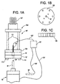
- Testing system 10 is comprised of a punch guide, generally at 12, which includes a punch die 14; a punch control assembly, generally at 16; a punch 44 (discussed more fully below); a remote displacement measurement system, generally at 18 and 50; and a punch displacement control system, generally at 20.
- Remote displacement measurement system 18 may be comprised of a laser sensor displacement measuring device 30 secured to laser sensor mounting bracket 32 that is, in turn, supported by a laser sensor holder 32a.
- the laser sensor displacement measuring device 30 may be any conventional, known commercially available device such as one available from Omron, Keyence, or other known manufacturers.
- a laser-type displacement measuring device device 30 as illustrated in Fig. 1A, may also be an LVDT (linear variable differential transformer) such as a commercially available DVRT (differential variable reluctance transducer) which is commercially available from Mirco-Strain Inc.
- LVDT linear variable differential transformer
- DVRT differential variable reluctance transducer
- device 30 (or 30') measures displacement of the top surface of the specimen at the axis of symmetry "AX" of the hemispherical head of the punch, while displacement device 50 measures punch 44's displacement. The difference is the change in thickness of the specimen at any instant in time.
- the apparatus is essentially the same (with like apparatus being similarly numbered) except that laser sensor 30, and its holder 32, is replaced by LVDT sensor 30' and its accompanying holder apparatus.
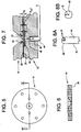
- Punch 44' having hemispherical head 46' with a radius R and drive control assembly 16' are essentially the same as that illustrated in Fig. 1.
- punch guide 12', punch die holder 32a', and punch die 14' are substantially similar to like items in Fig. 1 with only minor, conventional structural changes to 32a' and 14' as illustrated.
- displacement control system 20' and punch displacement sensor 50' remain the same, accumulating and/or sending data via lines 101', 103', and 105'.
- adjustable screw thread 107 LVDT holder plate assembly 109, and retaining columns 111 which are attached via cap screws 113.
- plate 19 contains various orifices for accommodating sensor 30' and structural retaining elements such as columns 111.
- specimen 22 initially positioned in undeformed condition between punch guide 12 and punch die 14 where specimen 22 is retained in cooperatively shaped recess 24 formed in an upper surface 26 of punch guide 12.
- a face surface 28 of punch die 14 overlies punch guide face surface 26 and acts to hold specimen 22 in place in its cooperatively shaped recess 24.
- specimen 22 is a small disc, generally planar in shape, so as to define substantially parallel upper (42) and lower (40) surfaces separated by the thickness of the specimen "t" (or "t o " before deformation).
- punch 44 includes a linearly extending cylindrical shaft portion 45 and a head 46 which is the end that contacts specimen 22 and creates the area of contact for deforming the specimen.
- punch head 46 is a true hemisphere, having a radius R (which is also the radius of cross-section of cylindrical shaft portion 45). Not only does the length of radius R thus become one of the factors in the above stress formula (a), but by specifying a true hemispherical shape, substantially equibiaxial deformation of the specimen is the result.
- die 14 is provided with a radius "r" at the end of its orifice contacting the specimen so as to prevent localized deformation of the specimen during the test.
- miniature disc specimen 22 may be fabricated, for example, from a sample of a sterilized implant.
- a convenient size for the disc specimen is 0.5mm (0.02 inches) in thickness and 6.4mm (0.25 inches) in diameter. Specimens of other dimensions are, of course, usable.
- Each disc specimen when formed has, as aforesaid, a bottom or lower face 40 and a top or upper face 42.
- first hemispherical end 46 will engage the bottom or front- side surface 40 of the miniature disc specimen 22.
- first hemispherical end 46 will engage the bottom or front- side surface 40 of the miniature disc specimen 22.
- specimen 22 will bow (bend) upwardly, and then, as further deformation occurs, to stretch and reduce thickness in a stretching (drawing) phase.
- further deformation will cause the specimen to rupture (i.e. fail).
- punch displacement control system 20 is constructed and is employed to do all calculations and to create signals to effect the required control of the apparatus, as well as to generate the data acquired from the calculations performed.
- the apparatus illustrated operates as follows:
- a properly sized specimen 22 is mounted as shown in Fig. 7.
- Head 46 is then brought into initial contact with frontside surface 40 and the actual deformation is then begun by advancing punch 44 at a predetermined rate controlled by a conventional drive mechanism in control element 16 which may include, for example, a conventional, commercially available servohydraulic test frame and actuator (e.g. manufactured by MTS Corp., Eden Prairie, MN). Testing is conducted at a constant predetermined temperature, for example, at room temperature 20°C. (68°F.) or, if desired, at an average human body temperature (37°C. or 98.6°F.).
- punch guide 12 is provided with orifice 201 into which there is inserted a conventional thermocouple 203 (Fig. 1) which is connected via line 205 to control system 20.
- Control system 20 then monitors any temperature change and provides the necessary environmental response (not shown) to maintain the temperature substantially constant (e.g. ⁇ 2°C. or less).
- Control assembly 20 may, for example, include a conventional microprocessor loaded with data acquisition, data analysis, and conventional control software capable of computing and controlling the rate of movement of punch 44, and in certain embodiments as discussed below, for also computing instantaneously the strain rate during deformation and in response thereto varying the rate of movement of punch 44, if necessary, to maintain a constant true strain rate.
- control assembly 20 acquires data from laser or LVDT sensor measuring device 30 or 30' via line 103 (or 103') which senses movement in topside surface 42 of the specimen.
- control assembly 20 Since all "variables" in formulae (1) and (2) above for computing the effective true stress and true strain are now known at that aforesaid particular point in time, control assembly 20 now calculates effective true stress and effective true strain for this specimen throughout any portion or all of the entire deformation cycle up to failure. From such data, then, curves, such as those shown in Figs. 9-10, may be generated for comparative purposes as aforesaid.
- each test should be conducted as nearly as possible under the same conditions. This includes, in certain preferred embodiments, conducting each test at substantially the same constant strain rate. This is because the degree, if any, of strain hardening and/or strain softening which can occur in various ductile polymers (e.g. polyethylene) during the drawing phase of deformation is or may be dependent on the rate of strain. Thus, to insure a more accurate comparative analysis, strain rate should be maintained substantially constant.
- a unique aspect of this invention is the providing of a small punch test apparatus which can achieve constant strain rate throughout deformation of the specimen. This is accomplished by control assembly 20 being adapted to include routinely designed software and feedback capabilities to the servohydraulic actuator in assembly 16 which controls the speed of punch 44 during deformation. Through the ability of this invention to calculate effective true strain in control assembly 20, acquisition of such data can then be used by assembly 20 (via line 101) to control the speed of punch 44 (and thus the change in thickness of specimen 22) to maintain the effective strain rate being calculated at a constant, often preselected, value.
- the specimen is placed in the device as illustrated schematically in Fig. 1A.
- Control assembly 20' includes a conventional microprocessor loaded with data acquisition, data analysis, and control software capable of instantaneously computing and controlling the effective true strain rate of the specimen throughout deformation. This is accomplished by control assembly 20' sending a signal via line 101' to the servohydraulic actuator (not shown for convenience) in head control assembly extension 16' to control the advancement of punch 44' to effect a predetermined effective true rate of strain at 0.01 sec -1 in the center of the specimen as contacted by the hemispherical head 46' of punch 44' having a radius of 0.05 inches (radius "r" of die 14 is 0.010 inches). The test is conducted and maintained at 20°C ⁇ 2°C. using the thermocouple control described above.
- the actuator is adjusted by the operator such that the head of the punch is placed in contact with the specimen retained in punch die 14'.
- the operator then changes from displacement control to strain control and starts the test.
- the control software in assembly 20' continuously acquires and computes the specimen thickness data being received from sensors 30' and 50' via lines 103' and 105', respectively, and computes thickness and effective instantaneous true strain therefrom. Any deviation from the present 0.01 sec -1 rate of strain is then adjusted via line 101' which signals the appropriate adjustment in the rate of advancement of punch 44'.
- load vs. displacement data is collected from the time of initial contact until failure of the specimen, and two curves are constructed.
- the first curve (Fig. 9) is load vs. displacement and the second curve (Fig. 9A) is effective true stress vs. effective true strain.
- the load vs. displacement curve is then used to determine the point "D", i.e. where the drawing or stretching phase began. This point is then located on the stress vs. strain curve to determine on this latter curve where the stretching phase began. This is accomplished by using the formulae (1) and (2) to correlate point D (Fig. 9) with stress and strain at that point on the stress/strain curve (Fig. 9A).
- point D is located at the initial peak load where it begins to drop off. This point, in most situations, defines where the stretching of the polymer has begun to dominate. In some circumstances the beginning of the dominant stretching phase is not manifested by this drop off, but rather by some other significant change in the shape of the curve. In such circumstances, as experience will dictate to the skilled artisan, point D will be at this location.
- a miniature disc-shaped specimen (0.250 inches in diameter and 0.020 inches in thickness) is machined from the second lot of UHMWPE and is tested using the same equipment as described in EXAMPLE 1 at 20°C. ⁇ 2°C. and at a constant effective true strain rate of 0.01 sec -1 which is maintained constant by the same procedure as in EXAMPLE 1.
- a second load vs. displacement curve (not shown) and another effective true stress vs. true strain curve are generated. This latter curve is then plotted as a dotted line marked ("M") in Fig. 9A and stretch initiation point Dm is located on the curve M for comparison with the standard "S" curve having its own point D.
- curve "M" differs markedly lower in stress and strain from curve "S", particularly beyond points D/Dm, and thus this new material is rejected as unacceptable for use as stock material for producing total joint replacement components.
- a lot-controlled, sterilized UHMWPE total joint replacement component (knee) is retrieved from "shelf" inventory to determine if the mechanical behavior of the lot has degraded during the term of shelf storage.
- the knee implant retrieved is placed in a milling machine and a standard coring tool is used to extract a core (approximately 0.275 inches in diameter) through the thickness of the implant.
- the central axis of the core is aligned perpendicular to the articulating surface of the implant.
- the core is then machined into three specimens labelled "a", "b”, and "c", respectively. Each has a diameter of 0.250 inches and a thickness of 0.020 inches.
- the first specimen “a” is machined starting at a depth of 0.000 to 0.001 inches of the articulating surface to achieve a thickness of 0.020 inches.
- the second specimen “b” is machined at a depth from 0.060 and 0.080 inches from the surface.
- the third specimen “c” is machined at a depth from 0.100 and 0.120 inches from the surface.
Landscapes
- Health & Medical Sciences (AREA)
- Life Sciences & Earth Sciences (AREA)
- Chemical & Material Sciences (AREA)
- General Health & Medical Sciences (AREA)
- Physics & Mathematics (AREA)
- Analytical Chemistry (AREA)
- Biochemistry (AREA)
- General Physics & Mathematics (AREA)
- Immunology (AREA)
- Pathology (AREA)
- Food Science & Technology (AREA)
- Medicinal Chemistry (AREA)
- Engineering & Computer Science (AREA)
- Investigating Strength Of Materials By Application Of Mechanical Stress (AREA)
Applications Claiming Priority (2)
| Application Number | Priority Date | Filing Date | Title |
|---|---|---|---|
| US281786 | 1999-03-31 | ||
| US09/281,786 US6267011B1 (en) | 1999-03-31 | 1999-03-31 | Method and apparatus for determining the true stress and true strain behavior of a ductile polymer |
Publications (2)
| Publication Number | Publication Date |
|---|---|
| EP1046899A2 true EP1046899A2 (fr) | 2000-10-25 |
| EP1046899A3 EP1046899A3 (fr) | 2001-07-25 |
Family
ID=23078780
Family Applications (1)
| Application Number | Title | Priority Date | Filing Date |
|---|---|---|---|
| EP00105422A Ceased EP1046899A3 (fr) | 1999-03-31 | 2000-03-15 | Méthode et dispositif pour la détermination du comportement d'un polymère ductile en vrai tension et vraie allongement |
Country Status (3)
| Country | Link |
|---|---|
| US (1) | US6267011B1 (fr) |
| EP (1) | EP1046899A3 (fr) |
| CA (1) | CA2300601C (fr) |
Cited By (8)
| Publication number | Priority date | Publication date | Assignee | Title |
|---|---|---|---|---|
| CN102692373A (zh) * | 2012-06-14 | 2012-09-26 | 华东理工大学 | 基于小冲杆测试技术的应力腐蚀敏感性评估装置 |
| CN103323331A (zh) * | 2013-07-09 | 2013-09-25 | 中南大学 | 通过普通压力机获得充填体试块应力-应变曲线的方法 |
| CN104568611A (zh) * | 2015-01-08 | 2015-04-29 | 泛亚汽车技术中心有限公司 | 基于dic应变测量系统的板料成形能力与变形均化能力评价方法 |
| CN105592948A (zh) * | 2013-05-20 | 2016-05-18 | 麦格纳国际公司 | 检测边缘裂纹 |
| CN106918501A (zh) * | 2016-11-25 | 2017-07-04 | 华东理工大学 | 多尺寸小冲杆试样夹持装置 |
| CN110470538A (zh) * | 2019-08-26 | 2019-11-19 | 浙江天能电池江苏新能源有限公司 | 蓄电池板栅时效性检测方法 |
| EP3839475A1 (fr) * | 2019-12-19 | 2021-06-23 | Fagor Arrasate, S.Coop. | Procédé et installation pour la déformation des matériaux |
| CN113432973A (zh) * | 2021-05-21 | 2021-09-24 | 四川长虹空调有限公司 | 一种快速获取钣金在高应变率下的应力应变数据的方法 |
Families Citing this family (20)
| Publication number | Priority date | Publication date | Assignee | Title |
|---|---|---|---|---|
| US20030157292A1 (en) * | 1999-06-23 | 2003-08-21 | Dataplay, Inc. | Miniature optical disk for data storage |
| US6963844B1 (en) * | 2000-04-06 | 2005-11-08 | Ford Motor Company | Method for qualifying die material and testing dies |
| US6772642B2 (en) * | 2001-08-24 | 2004-08-10 | Damian A. Hajduk | High throughput mechanical property and bulge testing of materials libraries |
| US7013709B2 (en) * | 2002-01-31 | 2006-03-21 | Symyx Technologies, Inc. | High throughput preparation and analysis of plastically shaped material samples |
| US7714054B2 (en) * | 2002-10-24 | 2010-05-11 | The University Of Akron | Process for making strain-hardened polymer products |
| US7849751B2 (en) | 2005-02-15 | 2010-12-14 | Clemson University Research Foundation | Contact sensors and methods for making same |
| WO2008115323A1 (fr) * | 2007-03-20 | 2008-09-25 | Exxonmobil Upstream Research Company | Procédé permettant de déterminer la capacité d'une structure |
| US7533577B1 (en) * | 2007-05-08 | 2009-05-19 | Livermore Software Technology Corporation | Determination of elastomer material properties for the Mullins effect using a bi-axial test device |
| US8042405B2 (en) * | 2008-07-23 | 2011-10-25 | University Of Kentucky Research Foundation | Method and apparatus for characterizing microscale formability of thin sheet materials |
| US8820173B2 (en) | 2009-03-06 | 2014-09-02 | Andrew C. Clark | Contact sensors and methods for making same |
| US9095275B2 (en) * | 2009-06-03 | 2015-08-04 | Andrew C. Clark | Contact sensors and methods for making same |
| US8766811B2 (en) * | 2011-01-21 | 2014-07-01 | Nike, Inc. | Compression testing device for testing materials automatically |
| WO2017048921A1 (fr) | 2015-09-15 | 2017-03-23 | Sencorables Llc | Système de capteur de contact avec le sol et procédés pour l'utiliser |
| JP6741271B2 (ja) * | 2016-10-06 | 2020-08-19 | 東京瓦斯株式会社 | 材料試験装置及び材料試験方法 |
| CN109406325B (zh) * | 2018-12-19 | 2021-04-20 | 中煤科工集团淮北爆破技术研究院有限公司 | 一种电雷管脚线耐磨性能测试方法 |
| CN110296903B (zh) * | 2019-07-17 | 2024-05-24 | 山东省医疗器械产品质量检验中心 | 异型接骨板力学性能测试装具及测试方法 |
| JP7385219B2 (ja) * | 2020-08-12 | 2023-11-22 | 東京瓦斯株式会社 | 試験装置 |
| CN112800645A (zh) * | 2021-01-05 | 2021-05-14 | 唐山钢铁集团有限责任公司 | 一种gissmo材料失效模型参数测量方法 |
| CN112924278B (zh) * | 2021-01-27 | 2022-09-27 | 中国科学院近代物理研究所 | 一种用于高能重离子辐照样品的小冲杆测试装置和方法 |
| CN119555503A (zh) * | 2025-01-13 | 2025-03-04 | 长安大学 | 连续纤维增强复合材料高温成形极限测试装置与方法 |
Family Cites Families (16)
| Publication number | Priority date | Publication date | Assignee | Title |
|---|---|---|---|---|
| US1237051A (en) | 1917-01-30 | 1917-08-14 | Pittsburgh Instr Machine Company | Testing apparatus. |
| US2262084A (en) | 1939-11-28 | 1941-11-11 | Alexander James Wolfe | Metal testing machine |
| US3274813A (en) * | 1962-03-28 | 1966-09-27 | Arde Portland Inc | Generalized stretch forming |
| US4062994A (en) * | 1971-07-27 | 1977-12-13 | National Research Development Corporation | Energy absorbing composite structures |
| US4432239A (en) | 1981-12-08 | 1984-02-21 | Bykov Anatoly P | Apparatus for measuring deformation |
| US4567774A (en) | 1983-04-28 | 1986-02-04 | Battelle Development Corporation | Determining mechanical behavior of solid materials using miniature specimens |
| JPS60244839A (ja) | 1984-05-19 | 1985-12-04 | Kureha Chem Ind Co Ltd | 材料試験装置 |
| US4839280A (en) * | 1987-05-04 | 1989-06-13 | Banes Albert J | Apparatus for applying stress to cell cultures |
| US4852397A (en) * | 1988-01-15 | 1989-08-01 | Haggag Fahmy M | Field indentation microprobe for structural integrity evaluation |
| US5165287A (en) | 1990-02-09 | 1992-11-24 | Battelle Columbus Division | Determining fracture mode transition behavior of solid materials using miniature specimens |
| US5184517A (en) | 1991-11-01 | 1993-02-09 | Robert Kelzer | Printed circuit board test fixture and method |
| KR940009403B1 (ko) | 1992-12-30 | 1994-10-13 | 포항종합제철주식회사 | 평면변형 장출성형성 평가장치 및 그 방법 |
| US5458002A (en) * | 1994-05-16 | 1995-10-17 | The B. F. Goodrich Company | Viscoelastic material testing system |
| JP2692599B2 (ja) | 1994-07-27 | 1997-12-17 | 株式会社島津製作所 | レーザー非接触伸び計 |
| DE19718615A1 (de) * | 1996-07-06 | 1998-01-08 | Cerasiv Gmbh | Verfahren zum Prüfen von keramischen Pfannen für Hüftgelenkendoprothesen |
| US5757473A (en) | 1996-11-13 | 1998-05-26 | Noranda, Inc. | Optical strain sensor for the measurement of microdeformations of surfaces |
-
1999
- 1999-03-31 US US09/281,786 patent/US6267011B1/en not_active Expired - Fee Related
-
2000
- 2000-03-14 CA CA002300601A patent/CA2300601C/fr not_active Expired - Fee Related
- 2000-03-15 EP EP00105422A patent/EP1046899A3/fr not_active Ceased
Cited By (12)
| Publication number | Priority date | Publication date | Assignee | Title |
|---|---|---|---|---|
| CN102692373A (zh) * | 2012-06-14 | 2012-09-26 | 华东理工大学 | 基于小冲杆测试技术的应力腐蚀敏感性评估装置 |
| CN105592948A (zh) * | 2013-05-20 | 2016-05-18 | 麦格纳国际公司 | 检测边缘裂纹 |
| CN105592948B (zh) * | 2013-05-20 | 2018-07-13 | 麦格纳国际公司 | 检测边缘裂纹 |
| US10670515B2 (en) | 2013-05-20 | 2020-06-02 | Magna International Inc. | Detecting edge cracks |
| CN103323331A (zh) * | 2013-07-09 | 2013-09-25 | 中南大学 | 通过普通压力机获得充填体试块应力-应变曲线的方法 |
| CN104568611A (zh) * | 2015-01-08 | 2015-04-29 | 泛亚汽车技术中心有限公司 | 基于dic应变测量系统的板料成形能力与变形均化能力评价方法 |
| CN104568611B (zh) * | 2015-01-08 | 2017-09-01 | 泛亚汽车技术中心有限公司 | 基于dic应变测量系统的板料成形能力与变形均化能力评价方法 |
| CN106918501A (zh) * | 2016-11-25 | 2017-07-04 | 华东理工大学 | 多尺寸小冲杆试样夹持装置 |
| CN110470538A (zh) * | 2019-08-26 | 2019-11-19 | 浙江天能电池江苏新能源有限公司 | 蓄电池板栅时效性检测方法 |
| CN110470538B (zh) * | 2019-08-26 | 2021-10-01 | 浙江天能电池江苏新能源有限公司 | 蓄电池板栅时效性检测方法 |
| EP3839475A1 (fr) * | 2019-12-19 | 2021-06-23 | Fagor Arrasate, S.Coop. | Procédé et installation pour la déformation des matériaux |
| CN113432973A (zh) * | 2021-05-21 | 2021-09-24 | 四川长虹空调有限公司 | 一种快速获取钣金在高应变率下的应力应变数据的方法 |
Also Published As
| Publication number | Publication date |
|---|---|
| US6267011B1 (en) | 2001-07-31 |
| CA2300601A1 (fr) | 2000-09-30 |
| EP1046899A3 (fr) | 2001-07-25 |
| CA2300601C (fr) | 2004-05-25 |
Similar Documents
| Publication | Publication Date | Title |
|---|---|---|
| US6267011B1 (en) | Method and apparatus for determining the true stress and true strain behavior of a ductile polymer | |
| Kurtz et al. | Validation of a small punch testing technique to characterize the mechanical behaviour of ultra-high-molecular-weight polyethylene | |
| Quinson et al. | Yield criteria for amorphous glassy polymers | |
| AU666012B2 (en) | Arthroscopic indenter | |
| Jang et al. | Assessing welding residual stress in A335 P12 steel welds before and after stress-relaxation annealing through instrumented indentation technique | |
| Swann et al. | Improved techniques for measuring the indentation and thickness of articular cartilage | |
| Kanters et al. | A new protocol for accelerated screening of long‐term plasticity‐controlled failure of polyethylene pipe grades | |
| Djebli et al. | Experimental analysis and damage modeling of high-density polyethylene under fatigue loading | |
| CN110736671B (zh) | 一种管件硬度异常部位的监测方法 | |
| Alar et al. | Application of instrumented Charpy method in characterisation of materials | |
| WO2018175008A1 (fr) | Presses d'emboutissage motorisée programmables pour fixer des aiguilles chirurgicales à des sutures | |
| Darlix et al. | Hardness measurement as a means of determining simultaneously the elastic modulus and yield stress of polymers as a function of temperature | |
| EP1631815B1 (fr) | Materiaux soumis a un essai | |
| CN116735389B (zh) | 基于低周疲劳试验获取弹塑性疲劳裂纹扩展速率的方法 | |
| Draghi | Static and uniaxial characterization of polymer biomaterials | |
| SU1666949A1 (ru) | Способ контрол степени свежести м са | |
| Merah et al. | Calibration of DC potential technique using an optical image processing system in LCF testing | |
| RU2445615C1 (ru) | Способ определения прочности материала изделия | |
| Hoo Fatt et al. | Fracture parameters for natural rubber under dynamic loading | |
| Bleck et al. | Measurement of the mechanical properties of car body sheet steels at high strain rates and non ambient temperature | |
| Arora et al. | Evaluation of the ASTM and ISO J initiation procedures by applying the unloading compliance technique to reactor pressure vessel steels | |
| Kannan et al. | Effect of specimen thickness and punch diameter in evaluation of small punch test parameters toward characterization of mechanical properties of Cr–Mo steels | |
| CN222050097U (zh) | 一种聚醚醚酮材料缺陷检测装置 | |
| CN112907033A (zh) | 一种基于偏最小二乘法的耐热钢劣化状态评估方法 | |
| Prakash | Evaluation of fatigue damage in materials using indentation testing and infrared thermography |
Legal Events
| Date | Code | Title | Description |
|---|---|---|---|
| PUAI | Public reference made under article 153(3) epc to a published international application that has entered the european phase |
Free format text: ORIGINAL CODE: 0009012 |
|
| AK | Designated contracting states |
Kind code of ref document: A2 Designated state(s): AT BE CH CY DE DK ES FI FR GB GR IE IT LI LU MC NL PT SE |
|
| AX | Request for extension of the european patent |
Free format text: AL;LT;LV;MK;RO;SI |
|
| PUAL | Search report despatched |
Free format text: ORIGINAL CODE: 0009013 |
|
| AK | Designated contracting states |
Kind code of ref document: A3 Designated state(s): AT BE CH CY DE DK ES FI FR GB GR IE IT LI LU MC NL PT SE |
|
| AX | Request for extension of the european patent |
Free format text: AL;LT;LV;MK;RO;SI |
|
| RIC1 | Information provided on ipc code assigned before grant |
Free format text: 7G 01N 3/08 A, 7G 01N 33/44 B, 7G 01N 3/28 B, 7G 01N 3/20 B |
|
| 17P | Request for examination filed |
Effective date: 20020124 |
|
| AKX | Designation fees paid |
Free format text: AT BE CH CY DE DK ES FI FR GB GR IE IT LI LU MC NL PT SE |
|
| 17Q | First examination report despatched |
Effective date: 20020531 |
|
| STAA | Information on the status of an ep patent application or granted ep patent |
Free format text: STATUS: THE APPLICATION HAS BEEN REFUSED |
|
| 18R | Application refused |
Effective date: 20050908 |