EP1047007A2 - Selbstbeschreibende Bauelemente - Google Patents
Selbstbeschreibende Bauelemente Download PDFInfo
- Publication number
- EP1047007A2 EP1047007A2 EP20000106170 EP00106170A EP1047007A2 EP 1047007 A2 EP1047007 A2 EP 1047007A2 EP 20000106170 EP20000106170 EP 20000106170 EP 00106170 A EP00106170 A EP 00106170A EP 1047007 A2 EP1047007 A2 EP 1047007A2
- Authority
- EP
- European Patent Office
- Prior art keywords
- block
- blocks
- connectors
- dimensional structure
- microcontroller
- Prior art date
- Legal status (The legal status is an assumption and is not a legal conclusion. Google has not performed a legal analysis and makes no representation as to the accuracy of the status listed.)
- Withdrawn
Links
Images






Classifications
-
- H—ELECTRICITY
- H05—ELECTRIC TECHNIQUES NOT OTHERWISE PROVIDED FOR
- H05K—PRINTED CIRCUITS; CASINGS OR CONSTRUCTIONAL DETAILS OF ELECTRIC APPARATUS; MANUFACTURE OF ASSEMBLAGES OF ELECTRICAL COMPONENTS
- H05K7/00—Constructional details common to different types of electric apparatus
- H05K7/14—Mounting supporting structure in casing or on frame or rack
- H05K7/1438—Back panels or connecting means therefor; Terminals; Coding means to avoid wrong insertion
- H05K7/1459—Circuit configuration, e.g. routing signals
-
- G—PHYSICS
- G06—COMPUTING OR CALCULATING; COUNTING
- G06F—ELECTRIC DIGITAL DATA PROCESSING
- G06F15/00—Digital computers in general; Data processing equipment in general
- G06F15/76—Architectures of general purpose stored program computers
- G06F15/80—Architectures of general purpose stored program computers comprising an array of processing units with common control, e.g. single instruction multiple data processors
- G06F15/8007—Architectures of general purpose stored program computers comprising an array of processing units with common control, e.g. single instruction multiple data processors single instruction multiple data [SIMD] multiprocessors
- G06F15/803—Three-dimensional arrays or hypercubes
-
- H—ELECTRICITY
- H01—ELECTRIC ELEMENTS
- H01R—ELECTRICALLY-CONDUCTIVE CONNECTIONS; STRUCTURAL ASSOCIATIONS OF A PLURALITY OF MUTUALLY-INSULATED ELECTRICAL CONNECTING ELEMENTS; COUPLING DEVICES; CURRENT COLLECTORS
- H01R13/00—Details of coupling devices of the kinds covered by groups H01R12/70 or H01R24/00 - H01R33/00
- H01R13/46—Bases; Cases
- H01R13/465—Identification means, e.g. labels, tags, markings
-
- H—ELECTRICITY
- H01—ELECTRIC ELEMENTS
- H01R—ELECTRICALLY-CONDUCTIVE CONNECTIONS; STRUCTURAL ASSOCIATIONS OF A PLURALITY OF MUTUALLY-INSULATED ELECTRICAL CONNECTING ELEMENTS; COUPLING DEVICES; CURRENT COLLECTORS
- H01R13/00—Details of coupling devices of the kinds covered by groups H01R12/70 or H01R24/00 - H01R33/00
- H01R13/46—Bases; Cases
- H01R13/514—Bases; Cases composed as a modular blocks or assembly, i.e. composed of co-operating parts provided with contact members or holding contact members between them
-
- H—ELECTRICITY
- H01—ELECTRIC ELEMENTS
- H01R—ELECTRICALLY-CONDUCTIVE CONNECTIONS; STRUCTURAL ASSOCIATIONS OF A PLURALITY OF MUTUALLY-INSULATED ELECTRICAL CONNECTING ELEMENTS; COUPLING DEVICES; CURRENT COLLECTORS
- H01R13/00—Details of coupling devices of the kinds covered by groups H01R12/70 or H01R24/00 - H01R33/00
- H01R13/66—Structural association with built-in electrical component
- H01R13/665—Structural association with built-in electrical component with built-in electronic circuit
-
- H—ELECTRICITY
- H01—ELECTRIC ELEMENTS
- H01R—ELECTRICALLY-CONDUCTIVE CONNECTIONS; STRUCTURAL ASSOCIATIONS OF A PLURALITY OF MUTUALLY-INSULATED ELECTRICAL CONNECTING ELEMENTS; COUPLING DEVICES; CURRENT COLLECTORS
- H01R29/00—Coupling parts for selective co-operation with a counterpart in different ways to establish different circuits, e.g. for voltage selection, for series-parallel selection, programmable connectors
Definitions
- This invention relates generally to building elements, and more particularly to a three-dimensional arrangement of the elements that is self-describing.
- each of Frazer's blocks had eight bits of state reflected in eight LEDs that could be controlled by a host computer.
- One of the blocks was equipped with six mercury tilt-switches to determine the orientation of the entire model.
- Another block had magnet-sensitive reed-switches embedded in external cladding panels. As the computer came to poll that block for its identify, the state of these switches could affect the result in a way that would in turn affect the virtual model's rendered appearance.
- Frazer also developed a modeling kit whose elements corresponded to the components used in kits for building actual modular homes.
- the miniature modeling kit included a variety of elements such as wall panels, doors and windows.
- Software on the computer drew plans ,gave feedback on planning errors, estimated costs and energy consumption, etc.
- Key attributes desired of self-describing construction kits include: scalability - the ability to build large structures containing hundreds of building elements, configurability - the ability to connect building elements in rich and varied ways, interactivity - the ability to interact physically and electrically with a constructed artifact, and presentation - the ability to design customized and stylized visual and physical interpretations of constructed artifacts.
- scalability the ability to build large structures containing hundreds of building elements
- configurability the ability to connect building elements in rich and varied ways
- interactivity the ability to interact physically and electrically with a constructed artifact
- presentation - the ability to design customized and stylized visual and physical interpretations of constructed artifacts.
- the invention provides a novel object-modeling system.
- the system includes building blocks that self-describe the geometric structures into which they are assembled.
- Each building block contains a microcontroller, and can communicate with the other blocks to which it is physically connected.
- the invention provides a novel architecture for a distributed computer system comprising self-describing building blocks with embedded microprocessors (microcontrollers).
- Each self-describing building block is formed of an enclosure having a top surface and a bottom surface.
- An array of m by n radially symmetric connectors are arranged on the top surface and on the bottom surface of the enclosure, wherein both m and n are greater than one if a rigid structure is required.
- the connectors are configured to carry power and data signals.
- a microcontroller, including a memory, is mounted in the enclosure.
- the microcontroller is coupled to each of the connectors.
- the microcontroller includes communication means for exchanging data messages using any of the connectors.
- the connectors enable a plurality of the blocks to be arranged in a rigid three-dimensional structure.
- This structure can be recovered by a distributed computation performed by the blocks, and passed to a host computer.
- the host computer can make the structure available for various applications, including virtual-reality computer games, information management for buildings, and artistic expression.
- the host can recover the geometric structure of the assembled blocks.
- the structure can then be rendered in various styles, ranging from a literal rendition, to decorative interpretations in which structural elements are identified automatically and augmented appropriately.
- the virtual models are available for viewing and manipulation by the user.
- the automatically decorated models can also be "replicated" using 3D stereolithography.
- each block can communicate with the host, and with the other blocks.
- Sensors in the blocks can report their status, and transducers such as lights, speakers, motors, etc., can be controlled.
- the blocks can be assembled into a model of an actual building, with sensors in the model being used to control the lighting in the building, and sensors in the building being used to control the corresponding lights in the model.
- the geometric arrangement of the blocks, as well as sensor data, and transducer controls can also be shared over a network, e.g., the Internet, permitting collaborative design, remote monitoring, and multi-user game playing, for example.
- a network e.g., the Internet
- our system concurrently achieves scalability, configurability, and interactivity, as well as a unique capability to enhance constructed artifacts through automatic, intelligent decoration. This is accomplished using a physical form factor that allows a rich and varied connectivity of building elements; a microprocessor-based, distributed, packet-switching architecture that facilitates efficient and robust computation of connectivity, and the autonomous operation of building elements during interactive use; and the automatic interpretation of constructed artifacts for the purpose of visual and physical decoration.
- Figures 1-2 shows a construction element 100 according to our invention.
- Figure 1 is a top view
- figure 2 is a bottom view.
- the element 100 is in the form of a 2x4x2 building block.
- 2x4x2 refers to the arrangement of the sixteen connectors on the top and bottom of each block. It should be noted that in general the invention admits any m x n array of connectors on the top and bottom of the block. However, to form a rigid structure both m and n need to be greater than one.
- Each block has a unique block identification number (BID), and each connector has an associated connector identification number (CIN 1 , ..., CIN 16 ).
- the block 100 is a two-part plastic enclosure having a top part 101 and removable bottom part 102.
- the parts can be fixed together with screws. Holes are formed in the top and bottom to mount connectors 103-104.
- the eight top holes are for plugs 103 (CIN 1 , ..., CIN 8 ), and the eight bottom holes mount jacks 104 (CIN 9 , ..., CIN 16 ).
- plugs 103 CIN 1 , ..., CIN 8
- bottom holes mount jacks 104
- CIN 9 a jack
- CIN 16 a connector that connects the blocks to be connected together in a wide range of orientations.
- the dimensions of the blocks ( m x n ), and the locations of the radially symmetric plugs and jacks are such that multiple blocks can be arranged into the same kind of 3D structures that one could create with LEGOTM building blocks.
- Each of the connectors 103-104 has two conductors (lines). However, instead of using one conductor for power and one for ground, which is the normal usage for a DC power connector, we use an inner conductor as a signal line 105 for bi-directional data communications, and an outer conductor or sleeve 106 for power distribution. In an alternative embodiment described below, a single conductor is used for both power and data signal. In this case, the power signal is modulated to carry the signal.
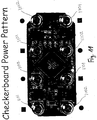
- the outer conductors 106 are wired so that adjacent connectors alternate power and ground signals on their outer sleeves, in a pattern similar to one described in U.S. Patent 4,883,440 "Electrified Toy Building Block with Zig-Zag Current Carrying Structure" issued to Bolli. Thus, every block will have at least one connection to power and one to ground in any typical structure built with the blocks.
- This supply voltage is then fed into a voltage regulator 330 that outputs correctly regulated power for the integrated circuits used within the block's circuitry.
- the voltage regulator ensures that the correct voltage is supplied to the circuitry independent of the input voltage to the regulator, so long as voltage is sufficiently high. This allows higher voltage, unregulated power to be distributed from block to block. This in turn allows a greater distance from the power source to the power consumer, and thereby enabling the construction of larger structures.
- Data communication according to our invention is done without the use of a global communication bus. Instead, we use a message passing protocol via the signal lines 105.
- Two holes 107 are formed in each side of the block.
- a light emitting diode (LED) is mounted behind each hole so that there is a visual indication of the block's operation.
- a circuit board 300 is mounted in the block 100.
- the connectors 103-104 are fixed to the circuit board, as are the LEDs 301.
- the connectors form the physical mounting basis for the circuit board.
- a microcontroller 310, the rectifier 320, and the voltage regulator 330 are mounted on the board.
- the microcontroller includes a random access memory.
- the board 300 also includes pads for the connector plugs and jacks, and assorted analog elements, i.e., resistors, capacitors, and a crystal to generate the clock for the microcontroller.
- circuit board Several pads in the periphery of the circuit board are left open to accommodate additional transducers and sensors inside the block, such as a speaker 110 shown in Figure 2, motors, RF, IR, ultrasound, and microwave transmitters, LED, LCD, CRT, and other display devices, cameras, microphones, proximity, presence, motion, and touch sensors 120, RF, IR, ultrasound, and microwave receivers, and the like.
- the current board can be trimmed to fit inside a 2x2x2 building block without affecting its basic functionality.
- the microcontroller 310 has thirty-three I/O pins of which sixteen are used for data communication via the signal lines of the connectors.
- the microcontroller includes an eight-bit RISC CPU, 8K of 14-bit words of read-only program memory (PROM), 368 8-bit bytes of data memory (RAM), a hardware Universal Synchronous/Asynchronous Receiver/Transmitter (USART), and interrupt handling.
- the data memory is used to store temporary data and connectivity information during operation.
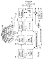
- the geometry of the three-dimensional structure is determined using a message-routing protocol.
- the low-level details of the protocol are described below.
- the protocol operates in three phases. Phase 1 determines connectivity, Phase 2 determines plug-to-jack correspondences, and in Phase 3, the connectivity database is sent, or "drained," to, for example, a host computer 480.
- the procedures that comprise the three phases operate in parallel 499 in the various blocks.
- the host computer can be a PC, workstation, or the like.
- Phase R Phase R
- This phase allows the blocks to communicate with each other or with the host, and for the host to communicate with the blocks.
- the blocks function as general-purpose network routers and are also able to autonomously determine the state of sensors and alter the state of transducers during this phase.
- Operation commences when we supply a power and ground signal on lines 401-402 to a drain block 403, described below. From the drain block(s), power is distributed to all of the blocks. When the blocks are powered on, they immediately enter Phase 1 (410). During Phase 1, the blocks determine their connectivity 411 in parallel. Lacking a global communication bus, the switching on of power is the only source of synchronization, which is necessarily approximate because of small delays in propagating power throughout the entire structure.
- All 16 signal lines of each block i.e., 8 connectors 103 on top and 8 connectors 104 on the bottom, are normally held high by pull-up resistors.
- Phase 1 is initiated by having each block pull its top signal lines (those in the plugs) low in response to the power signal.
- Each block then tests its bottom signal lines (the lines 105 in the jacks 104) to determine and store which have been pulled low by some other connected block. After a short delay, to ensure that the approximately synchronized blocks do not try to drive shared signal lines simultaneously in both directions, this test is repeated with the roles of the top and bottom signal lines reversed.
- each block has identified in parallel which of its signal lines are connected, i.e., which connectors are attached to other blocks, but not to which specific other blocks or connectors.
- each block After another short delay, each block enters Phase 2 (420).
- This phase has a first bottom-to-top half, and a second top-to-bottom half.
- blocks communicate with neighboring blocks over the connected signal lines identified in Phase 1 to determine plug-to-jack correspondence information 421.
- each block At the start of the first half of Phase 2, each block first listens on its connected bottom signal lines for transmitted messages that contain the BID of the transmitting block, BID T , and the connector number (CIN) of the connector over which that block is transmitting, CIN T .
- transmitted messages may be missed when the receiving block is busy when transmission commences. Electrical interference, or noise, may also corrupt a message. Therefore, all messages are transmitted using a check-summed, acknowledged protocol, and unacknowledged transmissions are retried a predetermined number of times after appropriate timeouts.
- the receiving block stores the message content along with its own BID number, BID R , and the connector number over which it received the transmission, CIN R , in its memory, e.g., (BID T , CIN T , BID R , CIN R ).
- This dataset forms a complete record of a single connection between two blocks.
- a database 450 of these records stores the local connectivity information in each block.
- each block has acquired and stored in its memory complete knowledge about all of its connected lines: the BIDs of the connected pair of blocks, and the corresponding connector numbers by which they are attached.
- the connectivity information (BIDs and CINs) is communicated to a host computer via the drain block 403, which includes a serial communication connection to the host computer.
- the drain In addition to mediating communication between a block structure and the host, the drain also supplies power to the connected blocks, and may be attached to any part of a block structure. In other words, the drain can be configured as block 100 with a serial connection.
- a drain block functions by reliably forwarding messages to a block connected to it; its existence is transparent to the algorithm.
- a block transmits connectivity messages containing all stored plug-to-jack correspondence information 421 on its "drain" connector, the one from which it received the request-to-drain message.
- the block After the block has successfully completed transmitting the connectivity messages, the block forwards the request-to-drain message on a valid line with the lowest connector number, and the block enters a message-forwarding mode.
- the block If the block receives a connectivity message in response to forwarding the request-to-drain message, then the block forwards that message on its drain connector. If the block receives any subsequent request-to-drain messages, then the block responds with a done message. If the block receives the done message, then the block forwards the request-to-drain message on a valid line with a higher connector number. If all valid lines have been processed, then the block sends a done message on its drain connector.
- the first request-to-drain message can be injected into the structure 400 by the drain block 403.
- the requests then percolate through the block structure in a preorder, depth-first traversal. Although this traversal is performed sequentially, that is, with only one block draining at any point in time, the forwarding of messages towards the drain is pipelined, thereby achieving parallelism in this phase as well.
- the host 480 has complete connectivity information for the block structure.
- the host has redundant connectivity information, because each connection is reported twice, once by each of the two connected blocks. This redundancy contributes to the robustness of the system, but it can be eliminated for efficiency by eliminating the second half of Phase 2.
- block structures are rigid, their geometry can be inferred deterministically from complete connectivity data. Using geometrical data so inferred, various renderings of block structures can be computed, as described below.
- Phase R (440) implements a scalable and responsive approach to providing interactivity. Blocks autonomously report events, rather than being polled for state changes. Using the route-to-drain found in Phase 3, messages about events are communicated in a store-and-forward fashion through a chain of blocks to the drain block, and on to the host.
- Phase R 440 blocks listen for general-purpose messages. Each message is check-summed, and successfully received messages are acknowledged. After a timeout, an unacknowledged message is retransmitted until successfully acknowledged.
- messages 460 are composed of a sequence of packets 461.
- Each packet contains a prefix 462 which includes a packet sequence number 466 and an optional route-to-drain indication 467.
- the packet-sequence number is used to guarantee that packets are received successfully and in the correct order. If the route-to-drain indication is present, then the packet is forwarded to the receiving block's drain connector without further processing.
- Each packet also includes a header 463, content 464, and a checksum 465.
- Phase-R packets are identified by packet type 468 in the header.
- the header also stores the length 469 of the packet.
- the accepted packet types include: (1) a Read/Write-RAM/registers packet, (2) a RAM/registers-contents packet, (3) an Alter-LEDs packet, (4) a Play-music packet, (5) a Route-packet-following-specified-path packet. This last packet type allows other packets to be sent to any other block.
- the specified path is determined by listing a sequence of Connector Identification Numbers (CIN) over which the packet should be forwarded. Using a form of "worm-hole" routing, each block sets up a forwarding path to the first CIN specified in the list and then removes that CIN from the list that is forwarded to the next block.
- CIN Connector Identification Numbers
- Phase R monitors the state of attached sensors, and upon determining a change, autonomously sends a RAM/registers-contents packet to the host, using the route-to-drain indicator, to notify the host of the change.
- the host is made aware of the state of all sensors on all of the blocks all of the time.
- the host may send packets to specified blocks, using the Route-packet type, to cause the blocks to change the state of attached transducers.
- the host is able to control accessories attached to the blocks.
- a message 460 is composed of one or more packets 461. Packets are composed of a sequence of separately synchronized bytes. Each packet contains an optional prefix byte 462, a message header 463, message-contents bytes 464, and a checksum 465. The prefix stores a sequence number 466 and a route-to-drain indication. The header stores a packet type 468 and a packet length 469. The content 464 can be routing information (CINs), or actual message-specific data.
- CINs routing information
- Packets are acknowledged, and unacknowledged packets are retransmitted using an adaptive timeout algorithm. Packets are transmitted in a pipelined fashion.
- the system using the protocol, as described herein emulates a self-configuring, store-and-forward computer network.
- This form of architecture facilitates transducers that require active control, such as speakers or motors, and sensors that require data buffering, such as microphones and cameras.
- the host 480 has access to a database (DB) 490.
- the database stores the BID 491 and attributes 492 for each block in the structure 400.
- the attributes can include shape, size, color, texture, and other physical or graphic information associated with the identified block. In other words, the attributes 492 can give the blocks additional characteristics.
- the attributes can be assigned when the blocks are given their unique BIDs.
- the database can be edited. This process is illustrated in Figure 12.
- a database 1200 stores the brick specific information. Connectivity information 1210 is received from Phase 3 as described above. Step 1220 infers the placement of the individual blocks. At this point, files 1231-1233, in various standard formats, describing the structure 400 can be generated.
- a graphics-rendering application 481 executing on the host can now graphically render 1240 the 3-D geometry 500 of the structure on an output device 485, and a user can perform Phase R interactions 1250 via a user interface.
- the application 481 can be any common 3D modeling system.
- Figure 6 shows a graphic 600 generated by the host from the physical block structure 500 shown in Figure 5.
- the rendered shape of the blocks can be different from the physical shape of blocks 100.
- the blocks are made to look like LEGOTM blocks.
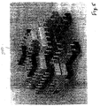
- Figure 10 the same structure 500 has been incorporated as a building 1000 in the well-known QuakeTM game. In this rendition, it actually becomes possible to "navigate" through the structure in a virtual-reality environment.
- the attributes given to the blocks include game effects, such as explosive walls, trap doors, electrified walls, etc.
- axioms 493 stored in the database 490 of Figure 4a, one axiom to assert the location, orientation, and identification (494) of each block.
- These axioms can serve as input to a logic-program application written in, for example, the Prolog language, to identify larger scale structural elements of a block structure through unification-driven pattern matching, e.g., the walls and roof of the structure 500 when the structure is to be interpreted as a building, see Appendix A and B for detailed examples.
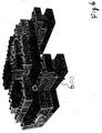
- the graphic 700 shows the identical physical structure rendered as a thatched roof cottage: note the brick texture, roof blocks modified to slope smoothly, and rendered with a mottled texture, and the additional fascia around the base of the roof.
- the pattern-matching rules can be expanded to recognize more structural elements of buildings, and to support additional rendering styles.
- interpretive and decorative rules for other modeled artifacts, such as vehicles or organic forms, can be devised.
- the augmented geometry of a structure can be transformed into an appropriate format for 3-D printing, e.g., via stereo lithography.
- 3-D printing e.g., via stereo lithography.
- the blocks 100 can be equipped with proximity and touch sensors so that the user can interact with the blocks in real-time.
- Sensor data is conveyed to the host computer via the Phase-R protocol described above.
- Transducers in the blocks are also controlled via Phase-R messages.
- a block-structure model can be created for a real-world building. Virtual representations of the building can be viewed on a computer display. By manipulating switches or sensors on the block structure, aspects of the real-world building such as lights and thermostats can be controlled. The status of real-world sensors can be reflected in the block model, e.g., by turning on LEDs or activating the speaker. In both instances, state and behavior data can also be depicted in the virtual model. More generally, any change of state in any one of the worlds can be reflected in any other worlds.
- our invention provides a tangible interface that allows users to fashion and manipulate virtual object models by simply building a physical structure.
- Object recognition allows a host computer to intelligently manipulate and augment the structures built by the user.
Landscapes
- Engineering & Computer Science (AREA)
- Computer Hardware Design (AREA)
- Theoretical Computer Science (AREA)
- Computer Networks & Wireless Communication (AREA)
- Microelectronics & Electronic Packaging (AREA)
- Computing Systems (AREA)
- Physics & Mathematics (AREA)
- General Engineering & Computer Science (AREA)
- General Physics & Mathematics (AREA)
- Toys (AREA)
- Multi Processors (AREA)
Applications Claiming Priority (2)
| Application Number | Priority Date | Filing Date | Title |
|---|---|---|---|
| US298236 | 1981-08-31 | ||
| US29823699A | 1999-04-23 | 1999-04-23 |
Publications (1)
| Publication Number | Publication Date |
|---|---|
| EP1047007A2 true EP1047007A2 (de) | 2000-10-25 |
Family
ID=23149638
Family Applications (1)
| Application Number | Title | Priority Date | Filing Date |
|---|---|---|---|
| EP20000106170 Withdrawn EP1047007A2 (de) | 1999-04-23 | 2000-03-21 | Selbstbeschreibende Bauelemente |
Country Status (2)
| Country | Link |
|---|---|
| EP (1) | EP1047007A2 (de) |
| JP (1) | JP2000305911A (de) |
Cited By (1)
| Publication number | Priority date | Publication date | Assignee | Title |
|---|---|---|---|---|
| CN120335377A (zh) * | 2025-06-18 | 2025-07-18 | 福州大学 | 一种用于连接器的对接控制方法及系统 |
Families Citing this family (1)
| Publication number | Priority date | Publication date | Assignee | Title |
|---|---|---|---|---|
| US11184245B2 (en) * | 2020-03-06 | 2021-11-23 | International Business Machines Corporation | Configuring computing nodes in a three-dimensional mesh topology |
-
2000
- 2000-03-01 JP JP2000056402A patent/JP2000305911A/ja not_active Abandoned
- 2000-03-21 EP EP20000106170 patent/EP1047007A2/de not_active Withdrawn
Cited By (1)
| Publication number | Priority date | Publication date | Assignee | Title |
|---|---|---|---|---|
| CN120335377A (zh) * | 2025-06-18 | 2025-07-18 | 福州大学 | 一种用于连接器的对接控制方法及系统 |
Also Published As
| Publication number | Publication date |
|---|---|
| JP2000305911A (ja) | 2000-11-02 |
Similar Documents
| Publication | Publication Date | Title |
|---|---|---|
| US6741245B1 (en) | Method for decorating a virtual model | |
| US6526375B1 (en) | Self-configuring store-and-forward computer network | |
| US8257157B2 (en) | Physical data building blocks system for video game interaction | |
| EP2202608B1 (de) | Systeme und Verfahren zur Übertragung physischer Objekte aus einem echten physischen Leben in virtuelle Welten | |
| US7555658B2 (en) | Embedded electronics building blocks for user-configurable monitor/control networks | |
| ES2277106T3 (es) | Procedimiento para generar un modelo legible por ordenador. | |
| CN203507551U (zh) | 一种电子积木 | |
| CN113348025B (zh) | 控制交互玩具构造模型的方法 | |
| US7370974B2 (en) | Toy with virtual character | |
| US6256719B1 (en) | Message-routing protocol for arbitrarily connected processors frankel | |
| EP1047017A2 (de) | Gleichzeitig wechselwirkende Objekte welche in verschiedenen Welten dargestellt sind | |
| EP2161658A1 (de) | Vorrichtung und Verfahren zur Erzeugung und Anzeige von visuellen Inhalten | |
| EP1047007A2 (de) | Selbstbeschreibende Bauelemente | |
| CN107452069A (zh) | 一种基于移动互联网和云平台的虚拟家装系统 | |
| EP1323136B1 (de) | Virtuelle-realität modellierung | |
| KR102301027B1 (ko) | 모듈을 이용한 독자 참여형 전자책 시스템 및 동작 방법 | |
| Boa et al. | Evolving lego: Prototyping requirements for a customizable construction kit | |
| Ichida et al. | ActiveCube and its 3D Applications | |
| CN104715787A (zh) | 新式具有断电保护的无源矩阵寻址的数据存储设备 | |
| CN103480159B (zh) | 玩具构建系统 | |
| CN211150058U (zh) | 一种基于级联拓扑的多电机立体展示装置 | |
| Sutphen et al. | Reviving a tangible interface affording 3D spatial interaction | |
| JP6177147B2 (ja) | 情報処理装置および情報処理方法 | |
| US20260098616A1 (en) | Light assembly and method thereof | |
| US11163917B2 (en) | Modular three-dimensional tile system |
Legal Events
| Date | Code | Title | Description |
|---|---|---|---|
| PUAI | Public reference made under article 153(3) epc to a published international application that has entered the european phase |
Free format text: ORIGINAL CODE: 0009012 |
|
| AK | Designated contracting states |
Kind code of ref document: A2 Designated state(s): AT BE CH CY DE DK ES FI FR GB GR IE IT LI LU MC NL PT SE |
|
| AX | Request for extension of the european patent |
Free format text: AL;LT;LV;MK;RO;SI |
|
| STAA | Information on the status of an ep patent application or granted ep patent |
Free format text: STATUS: THE APPLICATION HAS BEEN WITHDRAWN |
|
| 18W | Application withdrawn |
Effective date: 20040422 |