EP1047886B1 - Ensemble disque de frein notamment pour vehicules a moteur - Google Patents
Ensemble disque de frein notamment pour vehicules a moteur Download PDFInfo
- Publication number
- EP1047886B1 EP1047886B1 EP99902549A EP99902549A EP1047886B1 EP 1047886 B1 EP1047886 B1 EP 1047886B1 EP 99902549 A EP99902549 A EP 99902549A EP 99902549 A EP99902549 A EP 99902549A EP 1047886 B1 EP1047886 B1 EP 1047886B1
- Authority
- EP
- European Patent Office
- Prior art keywords
- brake disc
- flange
- brake
- assembly
- disc assembly
- Prior art date
- Legal status (The legal status is an assumption and is not a legal conclusion. Google has not performed a legal analysis and makes no representation as to the accuracy of the status listed.)
- Expired - Lifetime
Links
Images


Classifications
-
- B—PERFORMING OPERATIONS; TRANSPORTING
- B60—VEHICLES IN GENERAL
- B60B—VEHICLE WHEELS; CASTORS; AXLES FOR WHEELS OR CASTORS; INCREASING WHEEL ADHESION
- B60B27/00—Hubs
- B60B27/02—Hubs adapted to be rotatably arranged on axle
-
- F—MECHANICAL ENGINEERING; LIGHTING; HEATING; WEAPONS; BLASTING
- F16—ENGINEERING ELEMENTS AND UNITS; GENERAL MEASURES FOR PRODUCING AND MAINTAINING EFFECTIVE FUNCTIONING OF MACHINES OR INSTALLATIONS; THERMAL INSULATION IN GENERAL
- F16D—COUPLINGS FOR TRANSMITTING ROTATION; CLUTCHES; BRAKES
- F16D65/00—Parts or details
- F16D65/02—Braking members; Mounting thereof
- F16D65/12—Discs; Drums for disc brakes
- F16D65/123—Discs; Drums for disc brakes comprising an annular disc secured to a hub member; Discs characterised by means for mounting
-
- F—MECHANICAL ENGINEERING; LIGHTING; HEATING; WEAPONS; BLASTING
- F16—ENGINEERING ELEMENTS AND UNITS; GENERAL MEASURES FOR PRODUCING AND MAINTAINING EFFECTIVE FUNCTIONING OF MACHINES OR INSTALLATIONS; THERMAL INSULATION IN GENERAL
- F16D—COUPLINGS FOR TRANSMITTING ROTATION; CLUTCHES; BRAKES
- F16D65/00—Parts or details
- F16D65/02—Braking members; Mounting thereof
- F16D2065/13—Parts or details of discs or drums
- F16D2065/1304—Structure
- F16D2065/1316—Structure radially segmented
-
- F—MECHANICAL ENGINEERING; LIGHTING; HEATING; WEAPONS; BLASTING
- F16—ENGINEERING ELEMENTS AND UNITS; GENERAL MEASURES FOR PRODUCING AND MAINTAINING EFFECTIVE FUNCTIONING OF MACHINES OR INSTALLATIONS; THERMAL INSULATION IN GENERAL
- F16D—COUPLINGS FOR TRANSMITTING ROTATION; CLUTCHES; BRAKES
- F16D65/00—Parts or details
- F16D65/02—Braking members; Mounting thereof
- F16D2065/13—Parts or details of discs or drums
- F16D2065/1304—Structure
- F16D2065/1328—Structure internal cavities, e.g. cooling channels
-
- F—MECHANICAL ENGINEERING; LIGHTING; HEATING; WEAPONS; BLASTING
- F16—ENGINEERING ELEMENTS AND UNITS; GENERAL MEASURES FOR PRODUCING AND MAINTAINING EFFECTIVE FUNCTIONING OF MACHINES OR INSTALLATIONS; THERMAL INSULATION IN GENERAL
- F16D—COUPLINGS FOR TRANSMITTING ROTATION; CLUTCHES; BRAKES
- F16D65/00—Parts or details
- F16D65/02—Braking members; Mounting thereof
- F16D2065/13—Parts or details of discs or drums
- F16D2065/134—Connection
- F16D2065/1392—Connection elements
-
- F—MECHANICAL ENGINEERING; LIGHTING; HEATING; WEAPONS; BLASTING
- F16—ENGINEERING ELEMENTS AND UNITS; GENERAL MEASURES FOR PRODUCING AND MAINTAINING EFFECTIVE FUNCTIONING OF MACHINES OR INSTALLATIONS; THERMAL INSULATION IN GENERAL
- F16D—COUPLINGS FOR TRANSMITTING ROTATION; CLUTCHES; BRAKES
- F16D2250/00—Manufacturing; Assembly
- F16D2250/0084—Assembly or disassembly
Definitions
- the present invention relates to a brake disc assembly especially for motor vehicles with a brake disc, the at least one friction ring and a pot-shaped holding part with at least one radially continuous opening.
- the holding part is on via a flange attached to a rotating axis.
- Such a brake disc assembly is known from document JP-04 005 153.
- Another brake disc assembly for motor vehicles is disclosed in DE 43 14 311 A1. Owns there the one-piece brake disc has a friction ring and one with it connected brake disc chamber, which by means of fastening screws is attached to the flange of a wheel axle. The outer radial edge of the friction ring becomes as well as on both sides of the friction ring arranged brake pads from one Gripped the floating caliper disc brake.
- the Brake pads at least in the circumferential direction for transferring the Braking peripheral forces on an integrated in the steering knuckle Brake carrier guided and supported axially.
- the object of the invention is a brake disc assembly with a brake disc attached to a flange, with a simple assembly or disassembly of the brake disc on the flange is made possible.
- the task is solved by the characteristic features of claim 1.
- the real one Brake disc is particularly advantageous for cost reasons executed as a one-piece casting.
- the holding part has brake disc assembly / disassembly a cylindrical one oriented parallel to the brake disc axis Section a radially through opening. Thereby is the free movement of the brake disc in the assembly process significantly increased relative to the flange and thus allows the cheap brake disc assembly / disassembly even with unfavorable ones Installation situations for the brake or brake disc arrangement.
- the brake disc during assembly / disassembly so flexible on axially fixed flange arranged that the flange the opening in the holding part due to a radial relative displacement of the Brake disc to the flange at least in sections radially protruding from the inside out.
- This will make the measure of Mobility of the brake disc in relation to the flange increased and allows easy brake disc assembly / disassembly
- the radial may not be removed outer brake disc overlapping brake caliper or the brake carrier.
- the cup-shaped holding part of the brake disc a vertical fastening section oriented to the brake disc axis with a central through hole, where on Through hole in the same circumferential position as at the opening in the cylindrical section a radial recess is provided.
- the recess is particularly favorable the contour of a circular arc and thus increases the radial one Possibility of moving the brake disc compared to Flange during assembly.
- the brake disc using a separately mountable / demountable Centering ring opposite the flange with respect to Centered brake disc axis.
- the centering ring is there on corresponding centering surfaces of the flange and the Brake disc and ensures the desired positioning the brake disc.
- this makes balancing-free rotation possible the brake disc and the other through the independent mounting of the centering ring Brake disc assembly / disassembly further simplified in particular with corroded brake discs.
- the centering ring has at least one threaded hole or another device for example Appropriate tool for pulling off the centering ring from the flange or the brake disc.
- the flange preferably has a polygonal or polygonal shape Shape, the number of corners in particular with the number of wheel bolts used to attach the brake discs matches.
- the flange preferably has a polygonal or polygonal shape Shape, the number of corners in particular with the number of wheel bolts used to attach the brake discs matches.
- Embodiments of the invention are based on the drawing shown and explained in more detail below.
- the brake disc arrangement shown in Figures 1 and 2 has a brake disc 1, which has a cup-shaped holding part 2 attached to the flange 3 of a motor vehicle axle is.
- the one-piece brake disc 1 is through Cast produced and usually has at least one Friction ring 4 and a pot-shaped holding part that connects to it 2 on. It is for the basic idea of the invention however irrelevant whether the holding part 2 and friction ring 4 in one piece are connected or not.
- the holding part 2 is made from a parallel to the brake disc axis 5 cylindrical section 6 and a perpendicular to Brake disc axis 5 oriented fastening section 7.
- the brake disc 1 With the fastening section 7, the brake disc 1 through the wheel bolts 8 or wheel nuts over the wheel rim 9 axially braced against the flange system 10 and thus fixed in rotation on the vehicle axle, not shown.
- the wheel bearing 11 is also integrated in the flange 3, however, this is insignificant for the invention.
- the centering ring 12 is installed Condition on corresponding centering surfaces 13 of both Brake disc 1 and the flange 3 and thus ensures for precise positioning.
- the centering ring 12 has at least however, preferably a plurality of threaded bores 14 for attach suitable tools by means of which the centering ring 12 separately and therefore independent of the brake disc 1 can be removed from the flange 3.
- suitable tools for attach suitable tools by means of which the centering ring 12 separately and therefore independent of the brake disc 1 can be removed from the flange 3.
- threaded holes 14 are analogous to the execution of the threaded holes 14 and others Measures on the centering ring 12 possible, for example Allow disassembly with tool insert.
- the brake disk arrangement has the cup-shaped holding part 2 at least one radial on its cylindrical section 6 through opening 15.
- the cup-shaped holding part 2 at least one radial on its cylindrical section 6 through opening 15.
- two equally dimensioned Opposing openings 15 are provided.
- the openings 15 with the wheel rim 9 removed, removed wheel bolts 8 and already removed centering ring 12 the brake disc 1 relative to the flange 3 radially move such that the flange 3 at least in sections dips into one of the openings 15.
- the measure of radial displacement the brake disc 1 may be sufficient from the assembly / disassembly of the brake disc 1 without removing the brake caliper protruding from the edge of the brake disc to have to. Furthermore one reaches the Brake carrier overlapping brake disc edge, not shown, provided for the support and storage of the brake pads during brake disc assembly / disassembly in to keep its installation position. It is also supported by the Measures according to the invention allowed in the steering knuckle to realize integrated brake carrier designs, which the not only protrude the outer brake disc edge but also reach behind and for the nonetheless an easy one Brake disc assembly / disassembly is possible.
- FIGS. 1 and 2 are once again the individual components of the Brake disc arrangement can be seen, clearly recognizable is that the centering ring 12 by means of the threaded holes 14 can be removed independently and removed axially can be. Only after the centering ring 12 has been removed the necessary radial play between the fastening section 7 and flange 3, which mentioned the radial displacement of the Brake disc 1 permits.
- the flange preferably has a polygonal or polygonal contour, where the number of flange corners 16 with the number of used Wheel bolts 8 or wheel nuts match. While of the assembly process of the brake disc 1 projects through one of these Flange corners 16 the opening 15.
- the mounting position of the brake disc assembly is in Figure 3 shown.
- the previously between flange 3 and mounting section 7 arranged centering ring is already axially removed and the brake disc 1 is opposite Flange 3 shifted radially so far that a flange corner 16 into the opening 14 of the cylindrical holding section 6 dips.
- the brake disc 1 is also on an axial through hole 17 of the fastening section 7, in which the Flange 3 partially extends in the installed state, a radial Recess 18 provided (see also Figure 2).
- This recess 18 is advantageously the same in the circumferential direction Position like the opening 14 in the cylindrical holding portion 6 arranged.
- FIG. 4 shows a further variant of the brake disc arrangement, being used for reasons of component reduction an additional centering ring according to FIG. 2 is dispensed with has been.
- the brake disc 1 is centered here by appropriate centering surfaces 13 directly on Flange 3. Extends to maintain ease of assembly the opening 15 axially into a shielding groove 19, the an excessive shielding of the friction rings 4 due to thermal Should avoid stress. This allows axial assembly / disassembly the brake disc by means of a swiveling movement be carried out in a known manner.
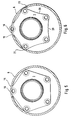
- FIG 5 and 6 are schematic representations of the Mounting position of the flange 3 within the cylindrical Holding section 6 shown.
- the cylindrical holding section 6 is so far radially with respect to the flange 3 moved that a flange corner 16, the opening 15 in the holding part projects through.
- the Measure of the maximum radial displacement of the brake disc on the one hand by the internal dimensions of the cylindrical section 6 and on the other hand by the dimensions or the geometric Design of the flange is limited.
- An enlargement the radial relative displacement between the flange 3 and brake disc 1 can, for example, according to FIG thereby achieve that the flanks 20 of the polygonal or polygonal flange have a concave curvature.
- inventive Basic idea is not on the inside of the drawing illustrated embodiments is limited. Leave it other flange geometries, for example, the required radial displacement of the brake disc allow during assembly / disassembly.
Landscapes
- Engineering & Computer Science (AREA)
- Mechanical Engineering (AREA)
- General Engineering & Computer Science (AREA)
- Braking Arrangements (AREA)
Abstract
Claims (6)
- Ensemble disque de frein, en particulier pour véhicules automobiles, avec un disque de frein (1) qui comporte au moins un anneau de friction (4) et un élément de maintien sensiblement en forme de pot, et avec une bride (3) sur laquelle le disque de frein (1) est fixé de manière séparable par l'intermédiaire de l'élément de maintien (2) en forme de pot, l'élément de maintien (2) possédant une portion (6) cylindrique s'étendant parallèlement à l'axe (5) du disque de frein et qui présente au moins une ouverture (15) continue radialement, caractérisé en ce que le disque de frein (1) à l'état de montage ou démontage, est disposé déplaçable sur la bride (3), de manière que, par suite d'un coulissement relatif radial du disque de frein (1) par rapport à la bride (3), la bride (3) traverse au moins en partie l'ouverture (15) dans l'élément de maintien (2).
- Ensemble disque de frein selon la revendication 1, caractérisé en ce que l'élément de maintien (2) en forme de pot du disque de frein (1) possède une portion de fixation (7) orientée perpendiculairement à l'axe (5) du disque de frein, avec un trou traversant (17) centré, la portion de fixation (7) présentant un évidement (18) radial dans le trou traversant (17), à la même position, dans la direction périphérique, que l'ouverture (15) dans la portion cylindrique (6).
- Ensemble disque de frein selon l'une des revendications précédentes, caractérisé en ce que pour le centrage du disque de frein (1) sur la bride (3), il est prévu une bague de centrage (12) qui vient s'appliquer contre des surfaces de centrage (13) correspondantes du disque de frein (1) et de la bride (3).
- Ensemble disque de frein selon la revendication 3, caractérisé en ce que la bague de centrage (12) présente au moins un trou taraudé (14) tourné à l'opposé de la bride (3).
- Ensemble disque de frein selon l'une des revendications précédentes, caractérisé en ce que la bride (3) est polygonale.
- Ensemble disque de frein selon la revendication 5, caractérisé en ce que les flancs (20) de la bride (3) polygonale présentent une courbure concave.
Applications Claiming Priority (3)
| Application Number | Priority Date | Filing Date | Title |
|---|---|---|---|
| DE19802040A DE19802040A1 (de) | 1998-01-21 | 1998-01-21 | Bremsscheibenanordnung, insbesondere für Kraftfahrzeuge |
| DE19802040 | 1998-01-21 | ||
| PCT/EP1999/000265 WO1999037937A1 (fr) | 1998-01-21 | 1999-01-18 | Ensemble disque de frein notamment pour vehicules a moteur |
Publications (2)
| Publication Number | Publication Date |
|---|---|
| EP1047886A1 EP1047886A1 (fr) | 2000-11-02 |
| EP1047886B1 true EP1047886B1 (fr) | 2003-07-02 |
Family
ID=7855177
Family Applications (1)
| Application Number | Title | Priority Date | Filing Date |
|---|---|---|---|
| EP99902549A Expired - Lifetime EP1047886B1 (fr) | 1998-01-21 | 1999-01-18 | Ensemble disque de frein notamment pour vehicules a moteur |
Country Status (3)
| Country | Link |
|---|---|
| EP (1) | EP1047886B1 (fr) |
| DE (2) | DE19802040A1 (fr) |
| WO (1) | WO1999037937A1 (fr) |
Families Citing this family (7)
| Publication number | Priority date | Publication date | Assignee | Title |
|---|---|---|---|---|
| DE10103485A1 (de) * | 2001-01-26 | 2002-08-01 | Volkswagen Ag | Befestigungsanordnung für eine Scheibenbremse |
| DE10321796B4 (de) | 2003-05-14 | 2008-02-14 | Daimler Ag | Bremsscheibe mit Reibring und Bremsscheibentopf |
| DE102011112230A1 (de) * | 2011-09-01 | 2013-03-07 | Daimler Ag | Halteanordnung für Radnabe und Bremsscheibe |
| DE102011112182A1 (de) * | 2011-09-01 | 2013-03-07 | Daimler Ag | Anordnung einer Bremsscheibe an einer Radnabe |
| FR3010756B1 (fr) * | 2013-09-18 | 2017-01-13 | Peugeot Citroen Automobiles Sa | Disque de frein d'un vehicule automobile |
| WO2017049168A1 (fr) * | 2015-09-16 | 2017-03-23 | Performance Friction Corporation | Ensemble de frein à disque |
| ITUB20155735A1 (it) * | 2015-11-19 | 2017-05-19 | Freni Brembo Spa | Campana di disco per freno a disco |
Family Cites Families (6)
| Publication number | Priority date | Publication date | Assignee | Title |
|---|---|---|---|---|
| DE2919411A1 (de) * | 1979-05-15 | 1980-11-27 | Daimler Benz Ag | Bremsscheibe fuer rad eines kraftfahrzeugs |
| GB2053416A (en) * | 1979-06-30 | 1981-02-04 | Dunlop Ltd | Mounting brake discs |
| DE3120021C2 (de) * | 1981-05-20 | 1987-07-09 | Daimler-Benz Ag, 7000 Stuttgart | Anordnung zur Radkühlung an Kraftfahrzeugen |
| DE3924849A1 (de) * | 1989-07-27 | 1991-02-07 | Daimler Benz Ag | Gegossene bremsscheibe fuer kraftfahrzeuge |
| JPH045153A (ja) * | 1990-04-20 | 1992-01-09 | Suzuki Motor Corp | ブレーキディスクの取付装置 |
| DE4314311A1 (de) * | 1993-04-30 | 1994-11-03 | Teves Gmbh Alfred | Achsschenkelanordnung für Kraftfahrzeuge |
-
1998
- 1998-01-21 DE DE19802040A patent/DE19802040A1/de not_active Withdrawn
-
1999
- 1999-01-18 DE DE59906182T patent/DE59906182D1/de not_active Expired - Fee Related
- 1999-01-18 EP EP99902549A patent/EP1047886B1/fr not_active Expired - Lifetime
- 1999-01-18 WO PCT/EP1999/000265 patent/WO1999037937A1/fr not_active Ceased
Also Published As
| Publication number | Publication date |
|---|---|
| EP1047886A1 (fr) | 2000-11-02 |
| DE19802040A1 (de) | 1999-07-22 |
| DE59906182D1 (de) | 2003-08-07 |
| WO1999037937A1 (fr) | 1999-07-29 |
Similar Documents
| Publication | Publication Date | Title |
|---|---|---|
| DE60012012T2 (de) | Herstellungsverfahren einer radnabeneinheit mit minimaler exzentrizität | |
| DE68903632T2 (de) | Gleitlageranordnung mit auswechselbarem messaufnehmer. | |
| EP0407719A1 (fr) | Palier pour essieux de roues de remorque | |
| DE60112336T2 (de) | Radhalter für fahrzeuge mit scheibenbremsen | |
| DE102008044339A1 (de) | Bremsscheibenanordnung für Scheibenbremsen | |
| DE19652694A1 (de) | Anordnung einer Bremsscheibe an einer Radnabe | |
| EP1047886B1 (fr) | Ensemble disque de frein notamment pour vehicules a moteur | |
| DE2936668C2 (de) | Radkörper-Bremsscheibe mit mindestens einem aus zwei Halbringen zusammengesetzten Bremsscheibenring, insbesondere für Schienenfahrzeuge | |
| DE19647391A1 (de) | Radnabenanordnung für Personen- oder Lastwagen | |
| WO2020156920A1 (fr) | Procédé de fabrication d'une roue de véhicule coulée | |
| WO2014032834A1 (fr) | Montage de roue comprenant un disque de frein à centrage de roue | |
| DE102020208673A1 (de) | Radlageranordnung und Verfahren zur Demontage | |
| DE68912319T2 (de) | Kraftfahrzeugantrieb mit elektrischen Bremsvorrichtungen. | |
| DE3708699A1 (de) | Befestigungsanordnung fuer einen bremsbelag zur sicherung des belages gegen radiale verschiebung | |
| EP1063442A2 (fr) | Disque de frein pour frein à disque | |
| EP0600227B1 (fr) | Charnière à rotule pour portières de voitures | |
| DE29902180U1 (de) | Radnabe mit einer Bremsscheibe für eine Scheibenbremse | |
| DE10259156B4 (de) | Radnabe für die Lagerung eines Fahrzeugsrades | |
| EP1619045B1 (fr) | Ecrou de roue pour fixation de roues de véhicules | |
| EP0464401A1 (fr) | Rotor de filage à bout ouvert | |
| DE102020209170B4 (de) | Radgewichtsbaugruppe | |
| EP3784916B1 (fr) | Support de roues pour un véhicule, en particulier pour un véhicule automobile, agencement d'un palier de roue au niveau d'un tel support de roues et véhicule | |
| EP1335144B1 (fr) | Ensemble de support de frein | |
| DE1025279B (de) | Ausgleichgetriebe fuer Kraftfahrzeuge | |
| DE29519479U1 (de) | Vorrichtung zur drehbaren Lagerung einer Radnabe auf dem Achszapfen einer Radachse |
Legal Events
| Date | Code | Title | Description |
|---|---|---|---|
| PUAI | Public reference made under article 153(3) epc to a published international application that has entered the european phase |
Free format text: ORIGINAL CODE: 0009012 |
|
| 17P | Request for examination filed |
Effective date: 20000821 |
|
| AK | Designated contracting states |
Kind code of ref document: A1 Designated state(s): DE FR IT |
|
| GRAH | Despatch of communication of intention to grant a patent |
Free format text: ORIGINAL CODE: EPIDOS IGRA |
|
| GRAH | Despatch of communication of intention to grant a patent |
Free format text: ORIGINAL CODE: EPIDOS IGRA |
|
| GRAA | (expected) grant |
Free format text: ORIGINAL CODE: 0009210 |
|
| AK | Designated contracting states |
Designated state(s): DE FR IT |
|
| REF | Corresponds to: |
Ref document number: 59906182 Country of ref document: DE Date of ref document: 20030807 Kind code of ref document: P |
|
| ET | Fr: translation filed | ||
| PLBE | No opposition filed within time limit |
Free format text: ORIGINAL CODE: 0009261 |
|
| STAA | Information on the status of an ep patent application or granted ep patent |
Free format text: STATUS: NO OPPOSITION FILED WITHIN TIME LIMIT |
|
| 26N | No opposition filed |
Effective date: 20040405 |
|
| PGFP | Annual fee paid to national office [announced via postgrant information from national office to epo] |
Ref country code: FR Payment date: 20050118 Year of fee payment: 7 |
|
| PG25 | Lapsed in a contracting state [announced via postgrant information from national office to epo] |
Ref country code: FR Free format text: LAPSE BECAUSE OF NON-PAYMENT OF DUE FEES Effective date: 20060131 |
|
| PGFP | Annual fee paid to national office [announced via postgrant information from national office to epo] |
Ref country code: IT Payment date: 20060131 Year of fee payment: 8 |
|
| REG | Reference to a national code |
Ref country code: FR Ref legal event code: ST Effective date: 20060929 |
|
| PGFP | Annual fee paid to national office [announced via postgrant information from national office to epo] |
Ref country code: DE Payment date: 20090131 Year of fee payment: 11 |
|
| PG25 | Lapsed in a contracting state [announced via postgrant information from national office to epo] |
Ref country code: IT Free format text: LAPSE BECAUSE OF NON-PAYMENT OF DUE FEES Effective date: 20070118 |
|
| PG25 | Lapsed in a contracting state [announced via postgrant information from national office to epo] |
Ref country code: DE Free format text: LAPSE BECAUSE OF NON-PAYMENT OF DUE FEES Effective date: 20100803 |