EP1048197A1 - Ensemble lames pour faucheuse rotative - Google Patents
Ensemble lames pour faucheuse rotative Download PDFInfo
- Publication number
- EP1048197A1 EP1048197A1 EP00303317A EP00303317A EP1048197A1 EP 1048197 A1 EP1048197 A1 EP 1048197A1 EP 00303317 A EP00303317 A EP 00303317A EP 00303317 A EP00303317 A EP 00303317A EP 1048197 A1 EP1048197 A1 EP 1048197A1
- Authority
- EP
- European Patent Office
- Prior art keywords
- blade
- adapter
- grooves
- fixed
- mower
- Prior art date
- Legal status (The legal status is an assumption and is not a legal conclusion. Google has not performed a legal analysis and makes no representation as to the accuracy of the status listed.)
- Granted
Links
- 210000005069 ears Anatomy 0.000 claims description 15
- 230000006835 compression Effects 0.000 claims description 4
- 238000007906 compression Methods 0.000 claims description 4
- 210000000883 ear external Anatomy 0.000 claims description 2
- 208000027418 Wounds and injury Diseases 0.000 description 1
- 230000006378 damage Effects 0.000 description 1
- 231100001261 hazardous Toxicity 0.000 description 1
- 210000003128 head Anatomy 0.000 description 1
- 208000014674 injury Diseases 0.000 description 1
- JEIPFZHSYJVQDO-UHFFFAOYSA-N iron(III) oxide Inorganic materials O=[Fe]O[Fe]=O JEIPFZHSYJVQDO-UHFFFAOYSA-N 0.000 description 1
- 238000006467 substitution reaction Methods 0.000 description 1
Images


Classifications
-
- A—HUMAN NECESSITIES
- A01—AGRICULTURE; FORESTRY; ANIMAL HUSBANDRY; HUNTING; TRAPPING; FISHING
- A01D—HARVESTING; MOWING
- A01D34/00—Mowers; Mowing apparatus of harvesters
- A01D34/01—Mowers; Mowing apparatus of harvesters characterised by features relating to the type of cutting apparatus
- A01D34/412—Mowers; Mowing apparatus of harvesters characterised by features relating to the type of cutting apparatus having rotating cutters
- A01D34/63—Mowers; Mowing apparatus of harvesters characterised by features relating to the type of cutting apparatus having rotating cutters having cutters rotating about a vertical axis
- A01D34/73—Cutting apparatus
- A01D34/733—Cutting-blade mounting means
Definitions
- the present invention relates to an assembly which permits a blade to be attached to and removed from a rotary mover without the use of tools.
- the present invention provides a mower blade assembly which permits the blade of a rotary mower to be attached to and removed from the mower without the use of tools. This is accomplished by securing the blade to a blade adapter and securing a fixed adapter to the mower.
- the respective adapters are formed so that they may be selectively interlocked with one another by a connection not requiring tools. As a result, the blade can be quickly attached to or removed from the mower by hand without the difficulties and potential for injury existent in conventional blade-changing arrangements.
- the assembly just described permits the user to remove a blade easily so that it can be sharpened or replaced and then resecured to the mower.
- Such an assembly also allows the user to readily substitute between different types of blades, viz., between blades which are designed for particular applications, such as mulching, bagging and side discharge.
- a blade assembly for a rotary mower comprising fastening means for fastening a mower blade to an engine drive shaft of a rotary mower; characterised in that the fastening means comprises: a blade adapter arranged to be secured to a blade for a rotary mower and a fixed adapter arranged to be secured to an engine drive shaft of a rotary mower; one of the adapters having a plurality of projections disposed in spaced relationship; and the other adapter having (a) a first plurality of grooves spaced to correspond to the spacing of said projections; and (b) a second plurality of correspondingly spaced grooves disposed in angularly offset relationship to said first plurality of grooves; and resilient biassing means allowing entry of the projections into the second grooves by way of the first grooves and providing a resilient bias maintaining the projections in the second grooves during use.
- an embodiment of the invention consists of four basic components: a blade 10, a blade adapter 12, a fixed adapter 14 and a compression spring 16.
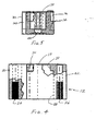
- the blade adapter 12 (shown in greater detail in Fig.4) comprises a substantially cylindrical element 18 having diametrically opposed outer ears 20 and 22 which are provided with internally threaded bores 24 and 26, respectively. These bores permit blade 10 to be secured to the blade adapter 12 by bolts, as can be appreciated from Fig.1.
- a substantially cylindrical inner wall 28 of element 18 is provided with a plurality of inwardly projecting, and equally spaced, ears 30 which have lengths corresponding to a portion of the length of element 18.
- the fixed adapter 14 (shown in greater detail in Fig.5) comprises a generally cylindrical body 32 having an outer diameter which is slightly less than the inner diameter of the blade adapter 12 defined by the inner wall 28 of element 18 (Fig.4).
- the outer wall of body 32 is provided with grooves 34 which are spaced to correspond with the spacing of the ears 30 of the blade adapter 12 and which extend for the entire length of body 32.
- the outer wall of body 32 includes at its upper end additional grooves 36 disposed between grooves 34.
- the grooves 36 also are spaced to correspond with the spacing of ears 30 of the blade adapter 12.
- the grooves 36 are dimensioned in width, depth and length to substantially correspond to the dimensions of the ears 30 whereby ears 30 can be received within respective grooves 36.
- Body 32 of the fixed adapter 14 also is provided at its upper end with a cylindrical recess 38 having a diameter slightly greater than the drive shaft of a mower engine.
- the bottom of recess 38 is provided with an opening 40 to permit the fixed adapter 14 to be secured by a bolt to the end of the mower's engine drive shaft in a manner which can be understood by reference to Fig.1.
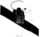
- the length of the fixed adapter 14 is substantially less than that of the blade adapter 12 for a reason which will become apparent from the description of the blade assembly which now will be presented with particular reference to Figs.1-3.
- the compression spring 16 is inserted within element 18.
- the ears 30 of the blade adapter 12 are aligned with the grooves 34 of the fixed adapter 14, and the blade adapter is slipped on to the fixed adapter (Fig.2). This occurs with pressure force so that spring 16 is compressed.
- the blade adapter is rotated relative to the fixed adapter (as indicated in Fig.3) to move ears 30 out of alignment with the grooves 34. Such relative rotation continues until the ears 30 are in alignment with the additional grooves 36.
- the force imparted by spring 16 causes the ears 30 to drop into the additional grooves 36 whereby the blade 10 is locked in position relative to engine drive shaft.
- the joined blade and blade adapter are forced upwardly towards the engine drive shaft. This compresses spring 16 and permits the blade adapter to move longitudinally relative to the fixed adapter until once again the lower edges of the ears 30 are above the upper surface of the fixed adapter. When this occurs, the blade adapter is rotated relative to the fixed adapter until ears 30 are in alignment with grooves 34, at which point the blade adapter can be slipped off the fixed adapter.
- the blade Once the blade has been removed from the detached blade adapter, it can be sharpened, or replaced and then resecured to the mower in the manner described above.
- a different type of blade e.g. a mulching blade
- a different type of blade can be installed on the mower in substitution for the previous blade.
Landscapes
- Life Sciences & Earth Sciences (AREA)
- Environmental Sciences (AREA)
- Harvester Elements (AREA)
Applications Claiming Priority (4)
| Application Number | Priority Date | Filing Date | Title |
|---|---|---|---|
| US13094399P | 1999-04-26 | 1999-04-26 | |
| US130943P | 1999-04-26 | ||
| US376297 | 1999-08-18 | ||
| US09/376,297 US6205755B1 (en) | 1999-04-26 | 1999-08-18 | Quick change blade assembly for a rotary mower |
Publications (2)
| Publication Number | Publication Date |
|---|---|
| EP1048197A1 true EP1048197A1 (fr) | 2000-11-02 |
| EP1048197B1 EP1048197B1 (fr) | 2004-02-25 |
Family
ID=26828997
Family Applications (1)
| Application Number | Title | Priority Date | Filing Date |
|---|---|---|---|
| EP00303317A Expired - Lifetime EP1048197B1 (fr) | 1999-04-26 | 2000-04-19 | Ensemble lames pour faucheuse rotative |
Country Status (6)
| Country | Link |
|---|---|
| US (1) | US6205755B1 (fr) |
| EP (1) | EP1048197B1 (fr) |
| AT (1) | ATE260020T1 (fr) |
| CA (1) | CA2306006C (fr) |
| DE (1) | DE60008451T2 (fr) |
| DK (1) | DK1048197T3 (fr) |
Cited By (4)
| Publication number | Priority date | Publication date | Assignee | Title |
|---|---|---|---|---|
| CN102278145A (zh) * | 2011-07-11 | 2011-12-14 | 袁新平 | 压力空气螺旋桨发动机 |
| EP2664229A1 (fr) * | 2012-05-16 | 2013-11-20 | PELLENC (Société Anonyme) | Dispositif sécurisé d'assemblage et de maintien d'une pièce entraînée avec une seconde pièce d'entraînement en rotation |
| WO2016037184A1 (fr) * | 2014-09-05 | 2016-03-10 | Mtd Products Inc | Lame de tondeuse à changement rapide |
| EP3466235A3 (fr) * | 2017-10-03 | 2019-05-01 | Deere & Company | Système de lame de tondeuse rotative à fixation rapide |
Families Citing this family (24)
| Publication number | Priority date | Publication date | Assignee | Title |
|---|---|---|---|---|
| US20030182919A1 (en) * | 2002-03-28 | 2003-10-02 | Baumann James R. | Deck assembly for a self-propelled, walk-behind rotary lawn mower |
| US6688095B2 (en) | 2002-03-28 | 2004-02-10 | The Toro Company | Blade coupler assembly for use with a self-propelled, walk-behind rotary lawn mower |
| US7127877B2 (en) | 2004-01-30 | 2006-10-31 | Briggs & Stratton Corporation | Universal mower blade |
| DE502004002618D1 (de) * | 2004-03-05 | 2007-02-22 | Wolf Outils | Schneidvorrichtung, insbesondere Rasenmäher |
| US7200982B2 (en) * | 2004-07-01 | 2007-04-10 | Briggs & Stratton Corporation | Blade slippage apparatus |
| US20060168933A1 (en) * | 2005-02-01 | 2006-08-03 | Hill Robert G Jr | Blade for rotary cutting machine |
| US7775026B2 (en) * | 2008-06-12 | 2010-08-17 | Christopher Bever | Lawn mower blade assembly for quick blade replacement and associated methods |
| US7784254B2 (en) | 2008-06-12 | 2010-08-31 | Christopher Bever | Lawn mower blade assembly having blade mount for quick blade replacement and associated methods |
| US7958710B2 (en) | 2009-06-26 | 2011-06-14 | Briggs & Stratton Corporation | Lawn mower blade coupling system |
| US7861503B1 (en) * | 2010-01-29 | 2011-01-04 | Deere & Company | Rotary cutting deck with hydraulic direct driven spindle |
| CN103957688B (zh) * | 2011-09-29 | 2015-12-09 | 胡斯华纳有限公司 | 快速更换刀片系统 |
| US20130269306A1 (en) | 2012-04-11 | 2013-10-17 | Briggs & Stratton Corporation | Noise-reducing mower blade |
| US8931248B2 (en) | 2012-06-12 | 2015-01-13 | Mtd Products Inc | Replaceable mower blade assembly |
| US8935909B2 (en) | 2012-06-12 | 2015-01-20 | Mtd Products Inc | Replaceable mower blade and assembly |
| WO2014152992A2 (fr) * | 2013-03-14 | 2014-09-25 | Husqvarna Ab | Lames de faucheuse à raccord rapide |
| US8869369B1 (en) | 2013-03-15 | 2014-10-28 | Jacob J Roach | Blade change carrier device |
| US9560800B2 (en) * | 2014-04-11 | 2017-02-07 | Deere & Company | Quick change rotary mower blade assembly |
| US9750183B2 (en) | 2015-07-21 | 2017-09-05 | Deere & Company | Quick attach rotary mower blade system |
| US9924632B2 (en) | 2016-05-20 | 2018-03-27 | Deere & Company | Quick connect mower blade system |
| USD911395S1 (en) * | 2019-03-06 | 2021-02-23 | Lambros Dimitracopoulos | Cutting blade |
| EP4104663B1 (fr) | 2021-06-09 | 2026-03-11 | Techtronic Cordless GP | Ensembles lames à libération rapide et procédés pour un outil électrique |
| US11679443B1 (en) | 2022-01-25 | 2023-06-20 | Lemco Products LLC | Apparatus for a quick release cutting device blade assembly |
| US20230363308A1 (en) * | 2022-05-10 | 2023-11-16 | Deere & Company | Quick change rotary mower blade system |
| US20240065146A1 (en) * | 2022-08-25 | 2024-02-29 | Mtd Products Inc | Blade adapter and mounting plate for multi-bladed mower |
Citations (7)
| Publication number | Priority date | Publication date | Assignee | Title |
|---|---|---|---|---|
| US2875569A (en) * | 1956-07-09 | 1959-03-03 | Wilbur C Sauer | Blade mounting means for rotary disc type mower |
| US3670413A (en) * | 1970-08-21 | 1972-06-20 | Black & Decker Mfg Co | Coupling for tool element |
| GB1562948A (en) * | 1978-01-27 | 1980-03-19 | Qualcast Ltd | Powered cutting or stripping tools |
| EP0438611A1 (fr) * | 1990-01-20 | 1991-07-31 | Dolmar GmbH | Dispositif d'immobilisation en rotation pour un organe rotatif, notamment pour un outil de coupe |
| EP0676127A1 (fr) * | 1994-04-08 | 1995-10-11 | WCI OUTDOOR PRODUCTS, Inc. | Tête de coupe pour dispositif de coupe fil flexible |
| WO1998018312A1 (fr) * | 1996-10-29 | 1998-05-07 | Conceptual Marketing & Development, Inc. | Tete de fixation pour dispositifs a couper la vegetation |
| US5862598A (en) * | 1992-12-10 | 1999-01-26 | Lee; Anthony L. | Unitary hub for vegetation cutting devices |
Family Cites Families (17)
| Publication number | Priority date | Publication date | Assignee | Title |
|---|---|---|---|---|
| US3783591A (en) * | 1971-12-23 | 1974-01-08 | H Williamson | Power mower safety mechanism |
| US3875728A (en) * | 1973-01-29 | 1975-04-08 | Fmc Corp | Bearing assembly |
| US3877146A (en) | 1973-11-28 | 1975-04-15 | Allegretti & Co | Rotating blade holder |
| US4041679A (en) * | 1974-02-01 | 1977-08-16 | Lester H. Seifert | Self-propelled rotary lawn mower |
| US4055935A (en) * | 1974-04-10 | 1977-11-01 | Malion William R | Clutch brake mechanism for lawnmowers |
| US4035994A (en) * | 1975-05-27 | 1977-07-19 | Hoffco, Inc. | Lawn mower blade control apparatus |
| US4084397A (en) * | 1975-12-29 | 1978-04-18 | Allis-Chalmers Corporation | Arbor assembly for rotary mowers |
| US4088210A (en) * | 1976-02-19 | 1978-05-09 | Hoffco, Inc. | Clutches with brake for implements |
| US4090345A (en) * | 1976-03-17 | 1978-05-23 | Briggs & Stratton Corporation | Brake safety system for a power driven rotary mower |
| US4229933A (en) | 1979-03-07 | 1980-10-28 | Bernard Roy A | Separable mower blade |
| US4586257A (en) | 1984-03-13 | 1986-05-06 | Rittenhouse James L | Releasable blade, blade holder and blade-holder combination |
| US4771593A (en) | 1986-06-23 | 1988-09-20 | Lee Harold D | Convertible blade hub |
| US4712364A (en) | 1986-06-30 | 1987-12-15 | Deere & Company | Quick attachable and detachable mower blade assembly |
| US4936884A (en) | 1988-12-20 | 1990-06-26 | Wesley R. Oder | Grass cutting device |
| US5456095A (en) | 1993-05-21 | 1995-10-10 | Tawil; David | Interchangeable setting for jewelry pieces |
| CA2109662C (fr) * | 1993-10-04 | 2002-01-29 | Gerhard Plamper | Lame de tondeuse avec trou d'entrainement en forme d'etoile |
| US5581985A (en) * | 1995-06-15 | 1996-12-10 | Secosky; Paul M. | Safety clutches for self power operated lawn mowers |
-
1999
- 1999-08-18 US US09/376,297 patent/US6205755B1/en not_active Expired - Lifetime
-
2000
- 2000-04-18 CA CA002306006A patent/CA2306006C/fr not_active Expired - Fee Related
- 2000-04-19 DE DE60008451T patent/DE60008451T2/de not_active Expired - Lifetime
- 2000-04-19 EP EP00303317A patent/EP1048197B1/fr not_active Expired - Lifetime
- 2000-04-19 AT AT00303317T patent/ATE260020T1/de not_active IP Right Cessation
- 2000-04-19 DK DK00303317T patent/DK1048197T3/da active
Patent Citations (7)
| Publication number | Priority date | Publication date | Assignee | Title |
|---|---|---|---|---|
| US2875569A (en) * | 1956-07-09 | 1959-03-03 | Wilbur C Sauer | Blade mounting means for rotary disc type mower |
| US3670413A (en) * | 1970-08-21 | 1972-06-20 | Black & Decker Mfg Co | Coupling for tool element |
| GB1562948A (en) * | 1978-01-27 | 1980-03-19 | Qualcast Ltd | Powered cutting or stripping tools |
| EP0438611A1 (fr) * | 1990-01-20 | 1991-07-31 | Dolmar GmbH | Dispositif d'immobilisation en rotation pour un organe rotatif, notamment pour un outil de coupe |
| US5862598A (en) * | 1992-12-10 | 1999-01-26 | Lee; Anthony L. | Unitary hub for vegetation cutting devices |
| EP0676127A1 (fr) * | 1994-04-08 | 1995-10-11 | WCI OUTDOOR PRODUCTS, Inc. | Tête de coupe pour dispositif de coupe fil flexible |
| WO1998018312A1 (fr) * | 1996-10-29 | 1998-05-07 | Conceptual Marketing & Development, Inc. | Tete de fixation pour dispositifs a couper la vegetation |
Cited By (10)
| Publication number | Priority date | Publication date | Assignee | Title |
|---|---|---|---|---|
| CN102278145A (zh) * | 2011-07-11 | 2011-12-14 | 袁新平 | 压力空气螺旋桨发动机 |
| EP2664229A1 (fr) * | 2012-05-16 | 2013-11-20 | PELLENC (Société Anonyme) | Dispositif sécurisé d'assemblage et de maintien d'une pièce entraînée avec une seconde pièce d'entraînement en rotation |
| FR2990593A1 (fr) * | 2012-05-16 | 2013-11-22 | Pellenc Sa | Dispositif securise d'assemblage et de maintien d'une piece entrainee avec une seconde piece d'entrainement en rotation |
| WO2016037184A1 (fr) * | 2014-09-05 | 2016-03-10 | Mtd Products Inc | Lame de tondeuse à changement rapide |
| US10299431B2 (en) | 2014-09-05 | 2019-05-28 | Mtd Products Inc | Quick change lawn mower blades |
| US10362730B2 (en) | 2014-09-05 | 2019-07-30 | Mtd Products Inc | Quick change lawn mower blades |
| US10674659B2 (en) | 2014-09-05 | 2020-06-09 | Mtd Products Inc | Quick change lawn mower blades |
| US10874049B2 (en) | 2014-09-05 | 2020-12-29 | Mtd Products Inc | Quick change lawn mower blades |
| EP3466235A3 (fr) * | 2017-10-03 | 2019-05-01 | Deere & Company | Système de lame de tondeuse rotative à fixation rapide |
| US10517212B2 (en) | 2017-10-03 | 2019-12-31 | Deere & Company | Quick attach rotary mower blade system |
Also Published As
| Publication number | Publication date |
|---|---|
| DK1048197T3 (da) | 2004-06-07 |
| CA2306006C (fr) | 2003-02-04 |
| CA2306006A1 (fr) | 2000-10-26 |
| US6205755B1 (en) | 2001-03-27 |
| ATE260020T1 (de) | 2004-03-15 |
| DE60008451T2 (de) | 2004-07-22 |
| DE60008451D1 (de) | 2004-04-01 |
| EP1048197B1 (fr) | 2004-02-25 |
Similar Documents
| Publication | Publication Date | Title |
|---|---|---|
| EP1048197B1 (fr) | Ensemble lames pour faucheuse rotative | |
| US5667332A (en) | Locking device for a drive shaft | |
| US7862277B2 (en) | Component interlocking | |
| RU2567456C2 (ru) | Кусторез | |
| US7367367B2 (en) | Replaceable tooth block for split wheel stump cutter | |
| US6877535B1 (en) | Split wheel stump cutter with replaceable tooth blocks and cutting teeth | |
| EP1656481B1 (fr) | Ensemble broche de connexion pour ensembles porte-pointes | |
| US4611418A (en) | Locking mechanism for earth excavation teeth | |
| US7958710B2 (en) | Lawn mower blade coupling system | |
| EP0819503A2 (fr) | Dispositif de verrouillage pour outil repliable | |
| US6839990B2 (en) | Excavator teeth | |
| EP3257643B1 (fr) | Foret à aspiration de poussière, sytème et unité d'aspiration de poussière | |
| US20120110970A1 (en) | Mower blade with replaceable inserts | |
| EP2649244A1 (fr) | Ensemble de connexion | |
| US7025149B2 (en) | Power tool with detachable drive end | |
| US4471603A (en) | Detachable blades for rotary mowers | |
| US5379535A (en) | Replaceable excavating tooth assembly | |
| EP0181093A1 (fr) | Outil | |
| CA2633421A1 (fr) | Ensemble de raccord | |
| EP0517645A1 (fr) | Verrou pour un boulon pour assembler un couteau dans une tondeuse et un dispositif à couteau avec ce verrou | |
| US20040166455A1 (en) | Variable tool | |
| AU2002307263B2 (en) | Impact tool with detachable drive end | |
| US20060188843A1 (en) | Variable tool | |
| EP0428798B1 (fr) | Connecteur | |
| WO2006080711A1 (fr) | Appareil de coupe rotatif magique |
Legal Events
| Date | Code | Title | Description |
|---|---|---|---|
| PUAI | Public reference made under article 153(3) epc to a published international application that has entered the european phase |
Free format text: ORIGINAL CODE: 0009012 |
|
| AK | Designated contracting states |
Kind code of ref document: A1 Designated state(s): AT BE CH CY DE DK ES FI FR GB GR IE IT LI LU MC NL PT SE |
|
| AX | Request for extension of the european patent |
Free format text: AL;LT;LV;MK;RO;SI |
|
| 17P | Request for examination filed |
Effective date: 20010309 |
|
| AKX | Designation fees paid |
Free format text: AT BE CH CY DE DK ES FI FR GB GR IE IT LI LU MC NL PT SE |
|
| GRAP | Despatch of communication of intention to grant a patent |
Free format text: ORIGINAL CODE: EPIDOSNIGR1 |
|
| GRAS | Grant fee paid |
Free format text: ORIGINAL CODE: EPIDOSNIGR3 |
|
| GRAA | (expected) grant |
Free format text: ORIGINAL CODE: 0009210 |
|
| AK | Designated contracting states |
Kind code of ref document: B1 Designated state(s): AT BE CH CY DE DK ES FI FR GB GR IE IT LI LU MC NL PT SE |
|
| PG25 | Lapsed in a contracting state [announced via postgrant information from national office to epo] |
Ref country code: BE Free format text: LAPSE BECAUSE OF FAILURE TO SUBMIT A TRANSLATION OF THE DESCRIPTION OR TO PAY THE FEE WITHIN THE PRESCRIBED TIME-LIMIT Effective date: 20040225 Ref country code: NL Free format text: LAPSE BECAUSE OF FAILURE TO SUBMIT A TRANSLATION OF THE DESCRIPTION OR TO PAY THE FEE WITHIN THE PRESCRIBED TIME-LIMIT Effective date: 20040225 Ref country code: CY Free format text: LAPSE BECAUSE OF FAILURE TO SUBMIT A TRANSLATION OF THE DESCRIPTION OR TO PAY THE FEE WITHIN THE PRESCRIBED TIME-LIMIT Effective date: 20040225 Ref country code: FI Free format text: LAPSE BECAUSE OF FAILURE TO SUBMIT A TRANSLATION OF THE DESCRIPTION OR TO PAY THE FEE WITHIN THE PRESCRIBED TIME-LIMIT Effective date: 20040225 Ref country code: LI Free format text: LAPSE BECAUSE OF FAILURE TO SUBMIT A TRANSLATION OF THE DESCRIPTION OR TO PAY THE FEE WITHIN THE PRESCRIBED TIME-LIMIT Effective date: 20040225 Ref country code: CH Free format text: LAPSE BECAUSE OF FAILURE TO SUBMIT A TRANSLATION OF THE DESCRIPTION OR TO PAY THE FEE WITHIN THE PRESCRIBED TIME-LIMIT Effective date: 20040225 |
|
| REG | Reference to a national code |
Ref country code: GB Ref legal event code: FG4D |
|
| REG | Reference to a national code |
Ref country code: CH Ref legal event code: EP |
|
| REG | Reference to a national code |
Ref country code: SE Ref legal event code: TRGR |
|
| REG | Reference to a national code |
Ref country code: IE Ref legal event code: FG4D |
|
| REF | Corresponds to: |
Ref document number: 60008451 Country of ref document: DE Date of ref document: 20040401 Kind code of ref document: P |
|
| PG25 | Lapsed in a contracting state [announced via postgrant information from national office to epo] |
Ref country code: IE Free format text: LAPSE BECAUSE OF NON-PAYMENT OF DUE FEES Effective date: 20040419 Ref country code: LU Free format text: LAPSE BECAUSE OF NON-PAYMENT OF DUE FEES Effective date: 20040419 |
|
| PG25 | Lapsed in a contracting state [announced via postgrant information from national office to epo] |
Ref country code: MC Free format text: LAPSE BECAUSE OF NON-PAYMENT OF DUE FEES Effective date: 20040430 |
|
| PG25 | Lapsed in a contracting state [announced via postgrant information from national office to epo] |
Ref country code: GR Free format text: LAPSE BECAUSE OF FAILURE TO SUBMIT A TRANSLATION OF THE DESCRIPTION OR TO PAY THE FEE WITHIN THE PRESCRIBED TIME-LIMIT Effective date: 20040525 |
|
| PG25 | Lapsed in a contracting state [announced via postgrant information from national office to epo] |
Ref country code: ES Free format text: LAPSE BECAUSE OF FAILURE TO SUBMIT A TRANSLATION OF THE DESCRIPTION OR TO PAY THE FEE WITHIN THE PRESCRIBED TIME-LIMIT Effective date: 20040605 |
|
| REG | Reference to a national code |
Ref country code: DK Ref legal event code: T3 |
|
| NLV1 | Nl: lapsed or annulled due to failure to fulfill the requirements of art. 29p and 29m of the patents act | ||
| REG | Reference to a national code |
Ref country code: CH Ref legal event code: PL |
|
| ET | Fr: translation filed | ||
| PLBE | No opposition filed within time limit |
Free format text: ORIGINAL CODE: 0009261 |
|
| STAA | Information on the status of an ep patent application or granted ep patent |
Free format text: STATUS: NO OPPOSITION FILED WITHIN TIME LIMIT |
|
| REG | Reference to a national code |
Ref country code: IE Ref legal event code: MM4A |
|
| 26N | No opposition filed |
Effective date: 20041126 |
|
| PG25 | Lapsed in a contracting state [announced via postgrant information from national office to epo] |
Ref country code: PT Free format text: LAPSE BECAUSE OF NON-PAYMENT OF DUE FEES Effective date: 20040725 |
|
| PGFP | Annual fee paid to national office [announced via postgrant information from national office to epo] |
Ref country code: GB Payment date: 20100325 Year of fee payment: 11 |
|
| PGFP | Annual fee paid to national office [announced via postgrant information from national office to epo] |
Ref country code: DK Payment date: 20100412 Year of fee payment: 11 Ref country code: FR Payment date: 20100521 Year of fee payment: 11 |
|
| PGFP | Annual fee paid to national office [announced via postgrant information from national office to epo] |
Ref country code: IT Payment date: 20100421 Year of fee payment: 11 Ref country code: AT Payment date: 20100413 Year of fee payment: 11 Ref country code: DE Payment date: 20100430 Year of fee payment: 11 |
|
| PGFP | Annual fee paid to national office [announced via postgrant information from national office to epo] |
Ref country code: SE Payment date: 20100409 Year of fee payment: 11 |
|
| REG | Reference to a national code |
Ref country code: DE Ref legal event code: R119 Ref document number: 60008451 Country of ref document: DE |
|
| REG | Reference to a national code |
Ref country code: DE Ref legal event code: R119 Ref document number: 60008451 Country of ref document: DE |
|
| REG | Reference to a national code |
Ref country code: SE Ref legal event code: EUG |
|
| GBPC | Gb: european patent ceased through non-payment of renewal fee |
Effective date: 20110419 |
|
| REG | Reference to a national code |
Ref country code: AT Ref legal event code: MM01 Ref document number: 260020 Country of ref document: AT Kind code of ref document: T Effective date: 20110419 |
|
| REG | Reference to a national code |
Ref country code: FR Ref legal event code: ST Effective date: 20111230 |
|
| PG25 | Lapsed in a contracting state [announced via postgrant information from national office to epo] |
Ref country code: FR Free format text: LAPSE BECAUSE OF NON-PAYMENT OF DUE FEES Effective date: 20110502 |
|
| REG | Reference to a national code |
Ref country code: DK Ref legal event code: EBP |
|
| PG25 | Lapsed in a contracting state [announced via postgrant information from national office to epo] |
Ref country code: AT Free format text: LAPSE BECAUSE OF NON-PAYMENT OF DUE FEES Effective date: 20110419 Ref country code: IT Free format text: LAPSE BECAUSE OF NON-PAYMENT OF DUE FEES Effective date: 20110419 Ref country code: GB Free format text: LAPSE BECAUSE OF NON-PAYMENT OF DUE FEES Effective date: 20110419 |
|
| PG25 | Lapsed in a contracting state [announced via postgrant information from national office to epo] |
Ref country code: DK Free format text: LAPSE BECAUSE OF NON-PAYMENT OF DUE FEES Effective date: 20110430 |
|
| PG25 | Lapsed in a contracting state [announced via postgrant information from national office to epo] |
Ref country code: SE Free format text: LAPSE BECAUSE OF NON-PAYMENT OF DUE FEES Effective date: 20110420 |
|
| PG25 | Lapsed in a contracting state [announced via postgrant information from national office to epo] |
Ref country code: DE Free format text: LAPSE BECAUSE OF NON-PAYMENT OF DUE FEES Effective date: 20111031 |