EP1048261A2 - Appareil pour nettoyer les sols - Google Patents
Appareil pour nettoyer les sols Download PDFInfo
- Publication number
- EP1048261A2 EP1048261A2 EP00104218A EP00104218A EP1048261A2 EP 1048261 A2 EP1048261 A2 EP 1048261A2 EP 00104218 A EP00104218 A EP 00104218A EP 00104218 A EP00104218 A EP 00104218A EP 1048261 A2 EP1048261 A2 EP 1048261A2
- Authority
- EP
- European Patent Office
- Prior art keywords
- cleaning device
- floor cleaning
- sleeve
- turbine
- gutter
- Prior art date
- Legal status (The legal status is an assumption and is not a legal conclusion. Google has not performed a legal analysis and makes no representation as to the accuracy of the status listed.)
- Withdrawn
Links
- 238000004140 cleaning Methods 0.000 title claims abstract description 47
- 239000007788 liquid Substances 0.000 claims abstract description 66
- 238000005192 partition Methods 0.000 claims description 16
- 238000007789 sealing Methods 0.000 claims description 14
- 239000000203 mixture Substances 0.000 claims description 10
- 239000000463 material Substances 0.000 claims description 5
- 239000004810 polytetrafluoroethylene Substances 0.000 claims description 5
- 229920001343 polytetrafluoroethylene Polymers 0.000 claims description 5
- 239000002184 metal Substances 0.000 claims description 3
- 239000002245 particle Substances 0.000 description 6
- 230000000694 effects Effects 0.000 description 5
- 238000003860 storage Methods 0.000 description 5
- 238000005260 corrosion Methods 0.000 description 4
- 230000007797 corrosion Effects 0.000 description 4
- 230000008901 benefit Effects 0.000 description 3
- 239000012530 fluid Substances 0.000 description 3
- 230000009471 action Effects 0.000 description 2
- 238000000034 method Methods 0.000 description 2
- 230000008569 process Effects 0.000 description 2
- OKTJSMMVPCPJKN-UHFFFAOYSA-N Carbon Chemical compound [C] OKTJSMMVPCPJKN-UHFFFAOYSA-N 0.000 description 1
- 230000035508 accumulation Effects 0.000 description 1
- 238000009825 accumulation Methods 0.000 description 1
- 230000032683 aging Effects 0.000 description 1
- 229910052799 carbon Inorganic materials 0.000 description 1
- 239000012459 cleaning agent Substances 0.000 description 1
- 238000010276 construction Methods 0.000 description 1
- 239000003599 detergent Substances 0.000 description 1
- 239000004519 grease Substances 0.000 description 1
- 239000004615 ingredient Substances 0.000 description 1
- 238000009434 installation Methods 0.000 description 1
- 230000007774 longterm Effects 0.000 description 1
- 239000000314 lubricant Substances 0.000 description 1
- 238000005461 lubrication Methods 0.000 description 1
- 238000004519 manufacturing process Methods 0.000 description 1
- 230000005012 migration Effects 0.000 description 1
- 238000013508 migration Methods 0.000 description 1
- 230000035515 penetration Effects 0.000 description 1
- 230000002093 peripheral effect Effects 0.000 description 1
- 238000009987 spinning Methods 0.000 description 1
Images


Classifications
-
- F—MECHANICAL ENGINEERING; LIGHTING; HEATING; WEAPONS; BLASTING
- F04—POSITIVE - DISPLACEMENT MACHINES FOR LIQUIDS; PUMPS FOR LIQUIDS OR ELASTIC FLUIDS
- F04D—NON-POSITIVE-DISPLACEMENT PUMPS
- F04D29/00—Details, component parts, or accessories
- F04D29/08—Sealings
- F04D29/10—Shaft sealings
- F04D29/106—Shaft sealings especially adapted for liquid pumps
-
- A—HUMAN NECESSITIES
- A47—FURNITURE; DOMESTIC ARTICLES OR APPLIANCES; COFFEE MILLS; SPICE MILLS; SUCTION CLEANERS IN GENERAL
- A47L—DOMESTIC WASHING OR CLEANING; SUCTION CLEANERS IN GENERAL
- A47L11/00—Machines for cleaning floors, carpets, furniture, walls, or wall coverings
- A47L11/29—Floor-scrubbing machines characterised by means for taking-up dirty liquid
- A47L11/30—Floor-scrubbing machines characterised by means for taking-up dirty liquid by suction
-
- A—HUMAN NECESSITIES
- A47—FURNITURE; DOMESTIC ARTICLES OR APPLIANCES; COFFEE MILLS; SPICE MILLS; SUCTION CLEANERS IN GENERAL
- A47L—DOMESTIC WASHING OR CLEANING; SUCTION CLEANERS IN GENERAL
- A47L11/00—Machines for cleaning floors, carpets, furniture, walls, or wall coverings
- A47L11/40—Parts or details of machines not provided for in groups A47L11/02 - A47L11/38, or not restricted to one of these groups, e.g. handles, arrangements of switches, skirts, buffers, levers
-
- A—HUMAN NECESSITIES
- A47—FURNITURE; DOMESTIC ARTICLES OR APPLIANCES; COFFEE MILLS; SPICE MILLS; SUCTION CLEANERS IN GENERAL
- A47L—DOMESTIC WASHING OR CLEANING; SUCTION CLEANERS IN GENERAL
- A47L5/00—Structural features of suction cleaners
- A47L5/12—Structural features of suction cleaners with power-driven air-pumps or air-compressors, e.g. driven by motor vehicle engine vacuum
- A47L5/22—Structural features of suction cleaners with power-driven air-pumps or air-compressors, e.g. driven by motor vehicle engine vacuum with rotary fans
Definitions
- the present invention relates to a floor cleaning device, which is a cleaning tool attacking a floor surface, a cleaning liquid tank and a dirty liquid container and a suction unit to pick up one sprayed on the floor surface Cleaning liquid and transfer into the dirty liquid container includes.
- Such floor cleaning devices are in particular as Scrubbers used as a cleaning tool one or more cleaning brushes are used come who attack the floor surface to be cleaned and this with the help of the cleaning liquid clean. For this, the cleaning liquid is in the area the cleaning brushes are sprayed on the floor surface and then under the action of the suction unit along with loosened dirt from the floor surface resumed and in the dirty liquid container transferred.
- Suction unit for receiving the sprayed onto the floor surface Liquid and for transferring this liquid into the dirt container from a drive motor with turbine wheel attached to the free end of the motor shaft, where electric motor and turbine wheel from one Enclosures are enclosed.
- the housing faces in the area of the turbine wheel an axial inflow opening and radial Outflow openings for the conveyed air / liquid mixture on.
- an intermediate wall is provided in the area the turbine wheel has a passage opening for the motor shaft having. In the area of this passage opening can transfer fluid from the turbine compartment to the engine compartment occur and there moisture with the consequence of corrosion on the A-side engine mount and on the electrical Create parts. Such corrosion will the lifespan of the drive motor is reduced.
- the object and the aim of the invention are a seal for a generic floor cleaning device to find those with high reliability Moisture enters the engine compartment from the turbine compartment prevented in the area of the motor shaft.
- this seal should be as simple as possible in construction.
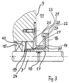
- This task is carried out in a generic floor cleaning device solved by the fact that on the motor shaft A centrifugal disc on the turbine side as a sealing device is provided, which is attached to a sleeve which is firmly connected to the motor shaft, wherein the sleeve the opening from the turbine compartment to the engine compartment penetrates and that the partition wall on the turbine side Has gutter, the diameter of the turbine side Wall of the gutter is less than or equal to that The diameter of the centrifugal wheel is and the gutter between the centrifugal wheel and the partition adjacent to the through hole for the motor shaft is arranged.
- the attachment of the centrifugal disc to a fixed the sleeve connected to the motor shaft, which covers the opening from the Turbine space interspersed with the engine compartment extends the Creepage distance for liquid that may be turbine side between the centrifugal wheel and the motor shaft could pass through the back pressure there.
- This Moisture is advantageous through the subsequent sleeve prevented from entering the engine compartment.
- the Connection of a gutter on the turbine side to the partition prevents liquid from coming from the Centrifugal force against the Partition wall was thrown or liquid that thrown directly against the partition by the turbine wheel is in the area of the passage opening for the Motor shaft can penetrate the bearing.
- the sleeve as a tread for a radial shaft seal serves, which is fixed to the housing, may be between the motor shaft and the inside of the centrifugal disc incoming liquid in a more advantageous Way at the entrance to the engine compartment and Bearing area of the motor shaft prevented.
- the seal namely for this liquid between the parts not moving relative to each other Sleeve and motor shaft.
- Such a seal is more reliable as a seal between moving parts, because no wear effect caused by the movement occurs on the sealing surfaces.
- the radial shaft seal is used as a sleeve seal is carried out, it sits particularly closely on the Sleeve on and it becomes a special this way good sealing effect achieved.
- a particularly good sealing behavior to the motor shaft is achieved when the sleeve is pressed onto the motor shaft becomes.
- An optimal seal between the sleeve and the centrifugal disc is achieved in that the sleeve in one piece with the centrifugal disc.
- the sleeve and the centrifugal disc advantageously consist made of hard, rustproof material, especially ST 1.4112. On the one hand, this leads to one very dimensionally stable design and thus high aging resistance. Another advantage of this choice of materials consists in the high corrosion resistance of the material. This plays especially with the use described a role in floor cleaning equipment because aggressive cleaning solutions are often used there come.
- centrifugal disc on the turbine side edge is chamfered on the perimeter in this area liquid droplets appearing are better thrown off and the adherence and migration of fluid accumulations along the centrifugal disc is prevented.
- a particularly good spin effect for those hitting Liquid particles are also beveled on the circumference on the motor-side edge of the centrifugal disc reached.
- Throttle gap for returning liquid that has penetrated intended.
- This throttle gap runs parallel to Intermediate wall and is chosen so narrow that there have occurred Liquid from the opposite wall of the gutter swept the spinning disc and through the resulting centrifugal forces from the Throttle gap is promoted.
- Providing a hard metal pad is particularly advantageous in the bearing area for the radial shaft seal. This makes durability in this area the seal increases because of the signs of wear are kept as low as possible on the sleeve.
- a particularly good sealing effect can also be achieved in this way be that the sleeve is made entirely of carbide exists and is pressed.
- An O-ring can be used as an additional seal between the sleeve and the motor shaft be provided to prevent the occurrence of Liquid between the sleeve and the motor shaft in the bearing area to reliably prevent the electric motor.
- the floor cleaning device consists of the on a floor surface attacking cleaning tool 1, the cleaning liquid tank 2, the dirty liquid container 3. With the suction unit 4 is on the floor surface 5 sprayed liquid into the dirty liquid container 3 transferred.
- the suction unit consists of a drive motor 6, which is designed as an electronically commutated motor is.
- a turbine wheel 8 put on.
- Electric motor 6 and turbine wheel 8 are enclosed by a housing 25.
- the housing 25 is with an intermediate wall 9 between engine compartment 10 and Turbine space 11 provided.
- an axial inflow opening 12 for the incoming Air / liquid mixture as well as radial outflow openings 13 provided.
- In the intermediate wall 9 is one Passage opening 14 for the free end of the motor shaft 7 provided. That from the turbine wheel 8 through the intake opening 12 air / liquid mixture is sucked axially sucked in and by the action of the turbine blades 8 conveyed radially through the outflow openings 13.
- the sleeve 17 is in one piece executed with the slinger 16 and prevented the passage of liquid in the sealing area between centrifugal disc 16 and motor shaft 7 could occur and get into the engine compartment 10 could.
- To prevent the penetration of creep liquid is the sleeve 17 with an O-ring 18 as a secondary seal provided for shaft 7.
- the sleeve 17 serves as a tread for a radial shaft seal 26, which is fixed to the housing 25.
- the Radial shaft sealing ring 26 serves to prevent the liquid from entering between housing 25 and sleeve circumference in that To prevent camp 15.
- the radial shaft seal also prevents leakage of lubricant (grease) 19 towards the turbine side.
- the radial shaft sealing ring 18 is a sleeve sealing ring executed. This consists of a disc, the Inner diameter is less than the outer diameter the sleeve 17 and the cuff-like on the Sleeve 17 is pulled up. This cuff seal 18 is made of PTFE.
- the sleeve 17 is on the motor shaft pressed on and there is thus a good seal reached.
- a gutter 27 between the partition 9 and centrifugal wheel 16 are provided in addition to the centrifugal wheel 16 is on the Partition 9 a gutter 27 between the partition 9 and centrifugal wheel 16 are provided. The gutter 27 is thereby as an independent part on the intermediate wall 9 of the Housing attached.
- the sleeve 17 and the centrifugal disc 16 consist of hard, rustproof Material, especially ST 1.4112.
- the paddle wheel 8 In suction mode, the paddle wheel 8 is driven by the drive motor 6 driven at high speed and sucks thereby an air / liquid mixture through the axial Intake opening 12. This air / liquid mixture is radial through the outlet openings 13 of the housing 8 promoted.
- the proportion of liquid in the air / liquid mixture is only very small since that Air / liquid mixture before entering the suction unit 4 has already passed the dirt container 3.
- In the dirt container 3 are separators 29 for the incoming liquid and the majority the liquid absorbed by the bottom surface 5 is deposited in the dirt container 3. At the in the air / liquid mixture entering the suction unit it is therefore only a question of residual moisture, which in is contained in the air.
- the turbine wheel 8 is generated a dynamic pressure in the axial direction.
- the air / liquid mixture strikes axially against the centrifugal wheel 16 and is reflected by this into the turbine chamber 11. Due to the air turbulence in the turbine room 11, however, it does not only result in an impact axial direction, but the slinger 16 is when operating the suction unit from all directions charged with finely divided liquid.
- the centrifugal disc 16 on the turbine side Edge 20 bevelled on the circumference.
- the partition 9 against the centrifugal disc 16 impinged liquid particles is the centrifugal disc 16 on the circumference on the motor side Edge 21 beveled.
- the liquid particles are therefore from the centrifugal disc 16 due to reflection forces or occurring Centrifugal forces thrown off.
- the slinger 16 is cranked on the outer circumference to the engine side and the Turbine-side gutter wall 21 is from this offset 22 attacks. This ensures that in the gap 23 between the gutter 19 and Centrifugal disc 16 fluid only from that of the turbines 8 side facing away from the occurring Apply axial pressure and therefore under the lowest possible pressure can. This is the preferred one Embodiment predominantly around fine liquid particles, the diagonally from the intermediate wall 9 against the Direction of delivery of the turbine blades to the gutter area be thrown back. These liquid particles step into the gap 23 between the gutter 27 and slinger 16. This gap 23 is very executed closely and merges into a conveyor gap 31. During operation, the one entered into this conveying gap 31 Liquid entrained by the centrifugal disc and from the centrifugal forces that occur promoted the gap 23, 31.
Landscapes
- Engineering & Computer Science (AREA)
- Mechanical Engineering (AREA)
- General Engineering & Computer Science (AREA)
- Cleaning By Liquid Or Steam (AREA)
- Sealing Using Fluids, Sealing Without Contact, And Removal Of Oil (AREA)
- Structures Of Non-Positive Displacement Pumps (AREA)
Applications Claiming Priority (2)
| Application Number | Priority Date | Filing Date | Title |
|---|---|---|---|
| DE1999119844 DE19919844A1 (de) | 1999-04-30 | 1999-04-30 | Bodenreinigungsgerät |
| DE19919844 | 1999-04-30 |
Publications (2)
| Publication Number | Publication Date |
|---|---|
| EP1048261A2 true EP1048261A2 (fr) | 2000-11-02 |
| EP1048261A3 EP1048261A3 (fr) | 2002-05-29 |
Family
ID=7906502
Family Applications (1)
| Application Number | Title | Priority Date | Filing Date |
|---|---|---|---|
| EP00104218A Withdrawn EP1048261A3 (fr) | 1999-04-30 | 2000-03-01 | Appareil pour nettoyer les sols |
Country Status (2)
| Country | Link |
|---|---|
| EP (1) | EP1048261A3 (fr) |
| DE (1) | DE19919844A1 (fr) |
Cited By (6)
| Publication number | Priority date | Publication date | Assignee | Title |
|---|---|---|---|---|
| WO2002069774A1 (fr) * | 2001-03-07 | 2002-09-12 | Alfred Kärcher Gmbh & Co. Kg | Appareil de nettoyage de sols |
| WO2003029657A1 (fr) * | 2001-10-01 | 2003-04-10 | BSH Bosch und Siemens Hausgeräte GmbH | Dispositif a appliquer dans un ensemble ventilateur |
| EP1334685A3 (fr) * | 2002-02-07 | 2005-03-09 | Johnson Electric S.A. | Moteur de ventilateur |
| CN1299010C (zh) * | 2000-11-17 | 2007-02-07 | 埃米特克有限公司 | 带有轴承保护系统的马达组件 |
| GB2539951A (en) * | 2015-07-02 | 2017-01-04 | Skf Ab | A seal assembly for a rotating shaft |
| US11542986B1 (en) * | 2019-09-30 | 2023-01-03 | Kevin Douglas Brady | Sealing system for bearing assembly for floor machine |
Family Cites Families (3)
| Publication number | Priority date | Publication date | Assignee | Title |
|---|---|---|---|---|
| US2635276A (en) * | 1946-02-15 | 1953-04-21 | Edward O Norris | Floor scrubbing and drying machine |
| US2726807A (en) * | 1950-09-28 | 1955-12-13 | Finnell System Inc | Vacuum apparatus for water and dirt removal |
| DE4447195C1 (de) * | 1994-12-30 | 1996-03-14 | Kaercher Gmbh & Co Alfred | Bodenreinigungsmaschine |
-
1999
- 1999-04-30 DE DE1999119844 patent/DE19919844A1/de not_active Withdrawn
-
2000
- 2000-03-01 EP EP00104218A patent/EP1048261A3/fr not_active Withdrawn
Cited By (7)
| Publication number | Priority date | Publication date | Assignee | Title |
|---|---|---|---|---|
| CN1299010C (zh) * | 2000-11-17 | 2007-02-07 | 埃米特克有限公司 | 带有轴承保护系统的马达组件 |
| WO2002069774A1 (fr) * | 2001-03-07 | 2002-09-12 | Alfred Kärcher Gmbh & Co. Kg | Appareil de nettoyage de sols |
| WO2003029657A1 (fr) * | 2001-10-01 | 2003-04-10 | BSH Bosch und Siemens Hausgeräte GmbH | Dispositif a appliquer dans un ensemble ventilateur |
| US7101148B2 (en) | 2001-10-01 | 2006-09-05 | Bsh Bosch Und Siemens Hausgeraete Gmbh | Device for use in a blower configuration |
| EP1334685A3 (fr) * | 2002-02-07 | 2005-03-09 | Johnson Electric S.A. | Moteur de ventilateur |
| GB2539951A (en) * | 2015-07-02 | 2017-01-04 | Skf Ab | A seal assembly for a rotating shaft |
| US11542986B1 (en) * | 2019-09-30 | 2023-01-03 | Kevin Douglas Brady | Sealing system for bearing assembly for floor machine |
Also Published As
| Publication number | Publication date |
|---|---|
| EP1048261A3 (fr) | 2002-05-29 |
| DE19919844A1 (de) | 2000-11-02 |
Similar Documents
| Publication | Publication Date | Title |
|---|---|---|
| DE3535445C2 (fr) | ||
| DE102005021278B4 (de) | Vorrichtung zum Reinigen von Gas beim Entlüften eines Kurbelgehäuses | |
| DE10157017C2 (de) | Staubsaugerbürste mit einem Putzlappen | |
| CH627236A5 (fr) | ||
| WO1998013610A1 (fr) | Palier, notamment pour machine electrique | |
| EP2450571A1 (fr) | Unité de bague collectrice et utilisation de l'unité de bague collectrice dans une éolienne | |
| EP1048261A2 (fr) | Appareil pour nettoyer les sols | |
| DE19846755B4 (de) | Pumpenvorrichtung für eine Waschanlage | |
| DE602004003738T2 (de) | Wasserpumpe für Dieselmotor mit Öldichtung | |
| DE102018123909B4 (de) | Kompakt-Gleitlager mit Dichtungsanordnung und Wasserpumpe mit demselben | |
| DE3787478T2 (de) | Flüssigkeitsgeschmierte und selbstschmierende Lageranordnung. | |
| EP1254330B1 (fr) | Dispositif pour etancheifier un volume | |
| EP1162716A2 (fr) | Moteur électrique, notamment moteur de ventilateur | |
| DE3902058A1 (de) | Wellenabdichtungssystem | |
| WO2003025436A1 (fr) | Dispositif d'etancheification assurant notamment l'etancheite de l'arbre d'une broche | |
| DE10342808B4 (de) | Turbolader mit Schmiermittelaustrageinrichtung | |
| DE69900973T2 (de) | Entleerungspumpe | |
| DE102009005775B4 (de) | Lagerabdichtungsanordnung | |
| DE3012916C2 (de) | Labyrinthwellendichtung | |
| DE10136169B4 (de) | Gehäuse mit einer austretenden Welle | |
| DE2629337C2 (de) | Flügelzellenvakuumpumpe | |
| EP1125072B1 (fr) | Systeme etanche pour une unite d'entrainement constituee d'un moteur et d'une transmission | |
| DE8915546U1 (de) | Kreiselpumpe mit trockenlaufgeeigneten Keramikgleitflächen | |
| EP3339652B1 (fr) | Pompe à vide avec chemise intérieure recueillant des dépôts | |
| DE2639540A1 (de) | Gleitlagerhuelse fuer die pumpenwelle von umwaelzpumpen fuer heizungs- und brauchwasseranlagen |
Legal Events
| Date | Code | Title | Description |
|---|---|---|---|
| PUAI | Public reference made under article 153(3) epc to a published international application that has entered the european phase |
Free format text: ORIGINAL CODE: 0009012 |
|
| AK | Designated contracting states |
Kind code of ref document: A2 Designated state(s): AT BE CH CY DE DK ES FI FR GB GR IE IT LI LU MC NL PT SE |
|
| AX | Request for extension of the european patent |
Free format text: AL;LT;LV;MK;RO;SI |
|
| PUAL | Search report despatched |
Free format text: ORIGINAL CODE: 0009013 |
|
| AK | Designated contracting states |
Kind code of ref document: A3 Designated state(s): AT BE CH CY DE DK ES FI FR GB GR IE IT LI LU MC NL PT SE |
|
| AX | Request for extension of the european patent |
Free format text: AL;LT;LV;MK;RO;SI |
|
| 17P | Request for examination filed |
Effective date: 20020622 |
|
| AKX | Designation fees paid |
Designated state(s): AT BE CH CY DE DK ES FI FR GB GR IE IT LI LU MC NL PT SE |
|
| RAP1 | Party data changed (applicant data changed or rights of an application transferred) |
Owner name: ALFRED KAERCHER GMBH & CO. KG |
|
| GRAP | Despatch of communication of intention to grant a patent |
Free format text: ORIGINAL CODE: EPIDOSNIGR1 |
|
| STAA | Information on the status of an ep patent application or granted ep patent |
Free format text: STATUS: THE APPLICATION IS DEEMED TO BE WITHDRAWN |
|
| 18D | Application deemed to be withdrawn |
Effective date: 20050907 |