EP1048385B1 - Kreisscheibenförmiges werkzeug - Google Patents
Kreisscheibenförmiges werkzeug Download PDFInfo
- Publication number
- EP1048385B1 EP1048385B1 EP98961371A EP98961371A EP1048385B1 EP 1048385 B1 EP1048385 B1 EP 1048385B1 EP 98961371 A EP98961371 A EP 98961371A EP 98961371 A EP98961371 A EP 98961371A EP 1048385 B1 EP1048385 B1 EP 1048385B1
- Authority
- EP
- European Patent Office
- Prior art keywords
- disc
- wear
- diameter
- base plate
- resistant
- Prior art date
- Legal status (The legal status is an assumption and is not a legal conclusion. Google has not performed a legal analysis and makes no representation as to the accuracy of the status listed.)
- Expired - Lifetime
Links
Images


Classifications
-
- B—PERFORMING OPERATIONS; TRANSPORTING
- B23—MACHINE TOOLS; METAL-WORKING NOT OTHERWISE PROVIDED FOR
- B23D—PLANING; SLOTTING; SHEARING; BROACHING; SAWING; FILING; SCRAPING; LIKE OPERATIONS FOR WORKING METAL BY REMOVING MATERIAL, NOT OTHERWISE PROVIDED FOR
- B23D61/00—Tools for sawing machines or sawing devices; Clamping devices for these tools
- B23D61/02—Circular saw blades
- B23D61/025—Details of saw blade body
- B23D61/026—Composite body, e.g. laminated
-
- B—PERFORMING OPERATIONS; TRANSPORTING
- B23—MACHINE TOOLS; METAL-WORKING NOT OTHERWISE PROVIDED FOR
- B23C—MILLING
- B23C5/00—Milling-cutters
- B23C5/02—Milling-cutters characterised by the shape of the cutter
- B23C5/08—Disc-type cutters
-
- C—CHEMISTRY; METALLURGY
- C23—COATING METALLIC MATERIAL; COATING MATERIAL WITH METALLIC MATERIAL; CHEMICAL SURFACE TREATMENT; DIFFUSION TREATMENT OF METALLIC MATERIAL; COATING BY VACUUM EVAPORATION, BY SPUTTERING, BY ION IMPLANTATION OR BY CHEMICAL VAPOUR DEPOSITION, IN GENERAL; INHIBITING CORROSION OF METALLIC MATERIAL OR INCRUSTATION IN GENERAL
- C23C—COATING METALLIC MATERIAL; COATING MATERIAL WITH METALLIC MATERIAL; SURFACE TREATMENT OF METALLIC MATERIAL BY DIFFUSION INTO THE SURFACE, BY CHEMICAL CONVERSION OR SUBSTITUTION; COATING BY VACUUM EVAPORATION, BY SPUTTERING, BY ION IMPLANTATION OR BY CHEMICAL VAPOUR DEPOSITION, IN GENERAL
- C23C30/00—Coating with metallic material characterised only by the composition of the metallic material, i.e. not characterised by the coating process
- C23C30/005—Coating with metallic material characterised only by the composition of the metallic material, i.e. not characterised by the coating process on hard metal substrates
-
- B—PERFORMING OPERATIONS; TRANSPORTING
- B23—MACHINE TOOLS; METAL-WORKING NOT OTHERWISE PROVIDED FOR
- B23C—MILLING
- B23C2210/00—Details of milling cutters
- B23C2210/24—Overall form of the milling cutter
- B23C2210/244—Milling cutters comprised of disc-shaped modules or multiple disc-like cutters
Definitions
- This invention relates to a process for manufacturing disc-shaped tools.
- tips having a coating film of titanium nitride (TiN), titanium carbide (TiC), titanium carbide nitride (TiC-N) and the like or layered coating films according to a combination of such titanium-containing films have conventionally been used widely.
- films of titanium aluminum nitride (Ti-Al-N) are particularly noted because of their excellent durability compared with the above films, and among others those having Ti/Al atomic ratios of 0.3 to 3 are put into practical uses.
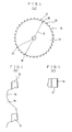
- disc-shaped tool 14 typified by the circular saw for cutting steel products, wood and the like, in which wear-resistant tips 12 are brazed to a disc-shaped steel base plate 10.
- the disc-shaped base plate 10 undergoes great deformation and buckling even under relatively small thermal stress. Accordingly, it is difficult to form a coating film which is excellent both in film quality and in adhesion.
- the base plate while film formation should be carried out with portions to be coated being maintained at a treating temperature of about several hundreds of °C, the base plate is caused to undergo high-temperature plastic deformation by the thermal stress attributed to nonuniform temperature distribution in the base plate. Since the deformation remains as a deformation, the base plate should not be subjected to high-temperature treatments. Thus, treatment of base plate at a low temperature at which no deformation occurs fails to give excellent film quality and adhesion strength.
- titanium nitride among others forms films well at relatively low treatment temperatures
- titanium carbide TiC
- titanium carbide nitride having a C/N atomic ratio of more than about 0.5 titanium carbide nitride having a C/N atomic ratio of more than about 0.5.
- Titanium aluminum nitride Ti-Al-N
- TiN titanium nitride
- 2,560,541 proposes to interpose an adherent coating layer of titanium nitride (TiN) between the surface of a base plate and a titanium aluminum nitride (Ti-Al-N) film so as to attain a tool having a titanium (Ti)-aluminum (Al) composite nitride coating layer adhered intimately to the surface of a base plate made of a cemented carbide or cermet.
- a high temperature treatment temperature
- film quality internal stress and toughness
- disc-shaped tools involve an inherent problem of "deformation” attributed to the high coating treatment temperature. Accordingly, conventional disc-shaped tools are merely of all-steel circular saws (metal slitting saws), having tips formed directly by notching peripheries of disc-shaped base plates made of high speed tool steel, coated with titanium nitride (TiN), or of cemented carbide-tipped circular saws (only those which are thick relative to their saw diameters) having a coating of, for example, titanium nitride (TiN) or titanium carbide nitride (Ti-C-N).
- TiN titanium nitride
- Ti-C-N titanium carbide nitride
- the coating film to be formed here is based on titanium nitride (TiN), and a TiC 0.6 N 0.4 film is sandwiched between titanium nitride films so as to improve hardness of the coating film.
- TiN titanium nitride
- a rather special system called arc discharge activate reaction ion plating system is used as a PVD system so as to enable film formation at low temperatures.
- the coating film is formed in each circular saw over the range of about 0.40 - 0.6 times the saw diameter (D) inward from the periphery.
- D saw diameter
- the metal slitting saws are used by repeating re-sharpening until their radii decrease by several tens millimeters, and thus the coating films should be formed over such range.
- the reasons why the coating films are formed over such a wide range as described above even in the cemented carbide-tipped circular saws are:
- the disc-shaped base plates constituting the saw bodies should be designed to have small thicknesses so as to achieve improvement of yield of the material in cutting, reduction of mechanical load, reduction of dust etc.
- steel cutting machines are provided with guides to prevent sawing deviation of the circular saws and to make up for the rigidity of the saws, enabling efficient cutting with thin saws.
- tips of circular saws used for such purposes are desired to have improved durability on the standpoint of improving running cost and productivity. Accordingly, it is now an important problem to improve further the durability of tips by applying surface treatment thereto as well as to optimize tip materials.
- the physical vapor deposition (PVD) method is suitably employed.
- PVD physical vapor deposition
- a disc-shaped base plate is subjected to ion bombardment in a PVD system prior to film formation to effect purification and preheating of the surface to be coated.
- the preheating of the disc-shaped base plate may be carried out using a heater housed separately in the PVD system.
- any residual deformation if occurs in a disc-shaped base plate brings about the necessity of intricate straightning treatment of the base plate, or other problems, for example, uncorrectable deformation.
- a circular base blade is disclosed.
- the circular base blade is divided into a central base blade and a ring-shaped circumferential base blade.
- the ring-shaped circumferential base blade comprises super hard cutting edges.
- the ring-shaped circumferential base blade is coated with a hard coating film, wherein during the coating process, the central base blade and the ring-shaped circumferential base blade are separated. Afterwards, the central base blade and the ring-shaped circumferential base blade are assembled.
- the circular saws 14 are fitted on a shaft (indicated by the reference number 22 in Fig. 4 ) standing at the center of a cylindrical vacuum chamber such that the shaft may penetrate central holes 24 of the circular saws 14, thus setting a multiplicity of circular saws 14 concentrically.
- a shim 20 is interposed every adjacent two circular saws 14 so as to secure a suitable clearance therebetween, and rings formed by cutting a pipe are conveniently used as the shims.
- the ion bombardment concentrates to the portions of the circular saws outer than the shims, and coating layers are formed on such portions only.
- the present invention prevents effectively occurrence of residual deformation by limiting the range of film formation utilizing the shims. That is, in view of the problems inherent in disc-shaped tools of the prior art having wear-resistant coating films, the present invention is directed to providing a coating technique of forming wear-resistant films capable of realizing high durability tools.
- Tests were carried out as indicated in Tables 1 and 3 in an arc ion plating system using titanium as a metal to be evaporated for forming PVD coating. Residual deformation to be caused by ion bombardment was tested for various types of discs and circular saws used as sample base plates to be tested, for example, having a diameter D of 360 mm and a thickness t of 2.25 mm while the size ds of the rings to be used as the shims were changed.
- the wall thickness of the rings was within the range of 7 to 15 mm for convenience' sake, since pipes having such thicknesses were used as raw materials for them.
- the width of the ring or the clearance to be secured between the base plates to be stacked up was 20 mm.
- the intensity of ion bombardment depends on the negative voltage and arc current to be applied to the sample discs and charge time. In the test of Table 1 and that of Table 3, ion bombardment was carried out at the fixed arc current 100 A. Some of the sample discs were preheated by a built-in heater for 60 minutes, followed immediately by ion bombardment. The temperature indicated in the column of preheating refers to the heater temperature.
- Test Nos. 12 to 14 (Table 3) were conducted, in which ion bombardment conditions were more intense than in those shown in Table 1.
- ion bombardment was carried out with an application voltage being increased to 900 V which is the upper limit competence of the system (arc current was 100 A).
- arc current was 100 A.
- Test Nos. 15 to 22 for disc-shaped base plates for circular saws were conducted.
- the circular saws are each provided with a gullet having a tooth number of 46.
- the diameter D is the distance from a gullet bottom (18 in Fig. 1(a),(b) ) to the opposing gullet bottom 18 across the central hole 24 (bottom-to-bottom diameter), the ratio of ring diameter ds to the bottom-to-bottom diameter D (ds/D) is shown.
- ds/D the ratio of ring diameter ds to the bottom-to-bottom diameter D
- Test Nos. 23 to 25 shown in Table 3 were carried out substantially under the service ceiling of the competence of the system. If saw-teeth having tips brazed thereto are subjected to ion bombardment treatment, the saw-teeth are heated to around a temperature at which the silver brazing alloy commonly employed for brazing of cemented carbide is denatured to have reduced strength. In this context, the above tests were carried out under the critical conditions.
- the peripheral portion of the circular saw which is induced to undergo heat expansion by the high temperature nevertheless, it is prevented from expanding fully by the low-temperature portion in the circular saw, and shrinkage by plastic deformation remained (so-called heat tension) as a result.
- This state is not necessarily undesired, since the heat tension occurred in thin circular saws for cutting lumber and wooden materials operated at high revolution of, for example, 1,500 r.p.m. or more can exhibit rather excellent sawing performance in some cases.
- coated tips brazed to the saw-teeth were of a cemented carbide corresponding to JIS M20, and coating conditions and evaluation of the films formed are shown in Table 4. Table 4 No.
- the titanium aluminum nitride (Ti-Al-N) coating of Test No. 28 had the same quality as in Test No. 27.
- the titanium carbide nitride (Ti-C-N) coating of Test No. 29 also underwent micro-spalling of intra-film, the degree of spalling was slightly higher than those in Test Nos. 27 and 28 and was of a permissible degree.
- the saw-teeth in any of Test Nos. 27, 28 and 29 showed improved wear resistance particularly at the peripheral flank and at lateral sides compared with that of the saw-teeth with no coating, showing transition of necessary cutting power consumption as shown in Fig. 3 . Thus, it was confirmed that the coating had good quality.
- the following points should be taken into consideration. That is, when a shim is interposed between every two circular saws for application of coating, the circular saws and shims are all desirably stacked to show high concentric accuracy. If the rings or shims offset greatly, nonuniform coating zones are formed circumferentially on the circular saws which can be another cause of deformation. However, a slight offset in arranging the rings is allowable, and nonuniform coating zones formed circumferentially due to partial deformation of the rings or to other reasons are not necessarily causative of troubles. In such cases, the ratio of ring diameter ds to saw diameter D (ds/D) in terms of the mean value of the entire circumference may be considered. Further, air vents may be formed in the rings so as to facilitate evacuation. While coating zones are partially formed inside the ring due to the presence of the air vents, the influence of such coating zones is small and is negligible.
- the present invention is directed to restricting the coating zone so as to form wear-resistant films depending on application with good adhesion and with excellent film quality, another coating may additionally be applied over a wider range, if necessary, in view of corrosion resistance and commercial value.
- titanium aluminum nitride (Ti-Al-N) over the range of 0.85 or more in terms of ds/D
- titanium nitride (TiN) coating is applied over the range of 0.50 or more in terms of ds/D.
- the diameter D, thickness t and the relationship t/D in the discs and the circular saw base plates in Examples of the present invention are as shown in Table 5.
- the base plate has a too poor rigidity to serve as a circular saw.
- Table 5 it was found from Table 5 that an excellent condition can be obtained if the present invention is applied when the relationship between the diameter D and the thickness t (t/D 2 ) is 3.68 x (1/10 5 ) or less.
- the present invention is effectively applied to disc-shaped tools in which t/D 2 is 3.7 x (1/10 5 ) or less, provided that D represents the diameter of the disc-shaped base plate, and t is the thickness of the base plate.
- a wear-resistant film with high durability can be obtained by setting a range of the tool to be coated with the film with respect to the diameter (D) of the base plate to not less than 0.75 times the diameter (D).
Landscapes
- Engineering & Computer Science (AREA)
- Mechanical Engineering (AREA)
- Chemical & Material Sciences (AREA)
- Chemical Kinetics & Catalysis (AREA)
- Materials Engineering (AREA)
- Metallurgy (AREA)
- Organic Chemistry (AREA)
- Physical Vapour Deposition (AREA)
- Cutting Tools, Boring Holders, And Turrets (AREA)
- Polishing Bodies And Polishing Tools (AREA)
Claims (7)
- Prozess zur Herstellung scheibenförmiger Werkzeuge (14), der die Schritte aufweist;- Vorsehen von scheibenförmigen Stahlbasisplatten (10), die verschleißfeste Spitzen (12) aufweisen, die aus Sinterkarbit, Cermet oder einer verschleißfesten Gusslegierung gefertigt sind, die darauf hartgelötet sind,;- koaxiales Einschieben einer Beilage (20) zwischen alle benachbarten zwei Basisplatten (10), so dass ein Zwischenabstand zwischen den Basisplatten (10) sichergestellt ist;- Anbringen eines verschleißfesten Überzugs mittels eines physikalischen Dampfabscheideverfahrens auf jede Seite jeder Basisplatte (10) über ein ringförmiges Gebiet, das sich außerhalb von der Beilage (20) befindet;- wobei der Durchmesser (ds) der Beilage (20) nicht kleiner als das 0,75 fache eines Durchmessers (D) der Basisplatten (10) ist.
- Prozess nach Anspruch 1, wobei der Durchmesser (ds) der Beilage (20) nicht kleiner als das 0,85 fache des Durchmessers (D) der Basisplatte (10) ist.
- Prozess nach Anspruch 1 oder 2, wobei ein Lötmaterial, das einen Zink (Zn) Anteil von weniger als 5% aufweist, zum Löten der verschleißfesten Spitzen (12) an die scheibenförmige Basisplatte verwendet wird.
- Prozess nach einem der Ansprüche 1 bis 3, wobei die scheibenförmige Stahlbasisplatte (10) aus einem Werkzeugstahl oder einem Baustahl gefertigt ist.
- Prozess nach einem der Ansprüche 1 bis 4, wobei der verschleißfeste Film als eine Hauptkomponente ein film-ausbildendes Material, das aus Titancarbid (TiC), Titancarbidnitrid (Ti-C-N), das ein C/N Atomverhältnis von mehr als 0,5 aufweist, und Titanaluminiumnitrid (Ti-Al-N) ausgewählt ist, aufweist.
- Prozess nach einem der Ansprüche 1 bis 4, wobei der verschleißfeste Film als eine Hauptkomponente Titanaluminiumnitrid (Ti-Al-N) aufweist, und das scheibenförmige Werkzeug (14) eine stahlschneidende Kreissäge (14) ist.
- Prozess nach einem der Ansprüche 1 bis 6, wobei t/D2 nicht mehr als 3,7 x (1/105) ist, vorausgesetzt, dass der Durchmesser der scheibenförmigen Basisplatte (10) D und die Dicke davon t ist.
Applications Claiming Priority (3)
| Application Number | Priority Date | Filing Date | Title |
|---|---|---|---|
| JP36403297 | 1997-12-16 | ||
| JP36403297 | 1997-12-16 | ||
| PCT/JP1998/005693 WO1999030862A1 (en) | 1997-12-16 | 1998-12-16 | Disc-shaped tool |
Publications (3)
| Publication Number | Publication Date |
|---|---|
| EP1048385A1 EP1048385A1 (de) | 2000-11-02 |
| EP1048385A4 EP1048385A4 (de) | 2007-02-21 |
| EP1048385B1 true EP1048385B1 (de) | 2008-10-01 |
Family
ID=18480813
Family Applications (1)
| Application Number | Title | Priority Date | Filing Date |
|---|---|---|---|
| EP98961371A Expired - Lifetime EP1048385B1 (de) | 1997-12-16 | 1998-12-16 | Kreisscheibenförmiges werkzeug |
Country Status (4)
| Country | Link |
|---|---|
| EP (1) | EP1048385B1 (de) |
| AT (1) | ATE409539T1 (de) |
| DE (1) | DE69840076D1 (de) |
| WO (1) | WO1999030862A1 (de) |
Families Citing this family (2)
| Publication number | Priority date | Publication date | Assignee | Title |
|---|---|---|---|---|
| ITUD20040082A1 (it) * | 2004-04-29 | 2004-07-29 | Pozzo Spa | Utensile per la lavorazione del legno o materiali affini, e relativo procedimento di realizzazione |
| WO2017113040A1 (zh) * | 2015-12-31 | 2017-07-06 | 唐山冶金锯片有限公司 | 金属冷热切圆锯片及其制造工艺 |
Family Cites Families (5)
| Publication number | Priority date | Publication date | Assignee | Title |
|---|---|---|---|---|
| DE3307702A1 (de) * | 1983-03-04 | 1984-09-06 | Philips Patentverwaltung Gmbh, 2000 Hamburg | Verfahren zum verbinden von bauteilen aus legierten staehlen mit keramischen bauteilen |
| JPH078452B2 (ja) * | 1991-02-12 | 1995-02-01 | 義信 小林 | 超硬刃付丸ノコ及びその製法 |
| JPH07276137A (ja) * | 1994-03-31 | 1995-10-24 | Osaka Diamond Ind Co Ltd | 切削・研削用工具 |
| JPH0825138A (ja) * | 1994-07-19 | 1996-01-30 | Nippon Steel Corp | チップソー |
| AU2600197A (en) * | 1996-04-04 | 1997-10-29 | Diamant Boart, Inc | Method of coating a cutting blade having improved wear characteristics |
-
1998
- 1998-12-16 EP EP98961371A patent/EP1048385B1/de not_active Expired - Lifetime
- 1998-12-16 AT AT98961371T patent/ATE409539T1/de not_active IP Right Cessation
- 1998-12-16 WO PCT/JP1998/005693 patent/WO1999030862A1/ja not_active Ceased
- 1998-12-16 DE DE69840076T patent/DE69840076D1/de not_active Expired - Lifetime
Also Published As
| Publication number | Publication date |
|---|---|
| EP1048385A1 (de) | 2000-11-02 |
| DE69840076D1 (de) | 2008-11-13 |
| ATE409539T1 (de) | 2008-10-15 |
| WO1999030862A1 (en) | 1999-06-24 |
| EP1048385A4 (de) | 2007-02-21 |
Similar Documents
| Publication | Publication Date | Title |
|---|---|---|
| KR100869956B1 (ko) | 고속도 공구강제 기어 절삭공구 및 그 제조방법 | |
| US5316321A (en) | Nonferrous piston ring with hard surface treatment layer | |
| KR100512269B1 (ko) | 내마모층으로 코팅된 공작물 | |
| EP3015206B1 (de) | Verfahren zur herstellung einer kreissäge mit harter spitze | |
| EP1726393B1 (de) | Kreissägeblatt mit mehrfachen Zentralbohrergrößen | |
| US5241748A (en) | Method for manufacturing a compression ring | |
| RU2364498C2 (ru) | Зажимное устройство | |
| US20060225553A1 (en) | Disk cutter having tip inserts coated with a hard material | |
| KR102719440B1 (ko) | 경질 피막을 가지는 절삭공구 | |
| EP1477575B1 (de) | Schneidwerkzeug zur Metallbearbeitung und Verfahren zur Herstellung von Schneidwerkzeugen | |
| EP1048385A1 (de) | Kreisscheibenförmiges werkzeug | |
| EP0506106B1 (de) | Schneidwerkzeug, Klemmhalter dafür und Verfahren zur Herstellung eines Schneidwerkzeugs | |
| KR20110120285A (ko) | 내마모성 클래딩층을 가진 절삭 공구 부품 | |
| JPH081412A (ja) | 積層被覆工具 | |
| EP1424176B1 (de) | Zinkenfugenschneider | |
| JP3454428B2 (ja) | 耐摩耗皮膜被覆工具 | |
| JPH0957817A (ja) | 2軸混練押出機用バレル | |
| JP2002337006A (ja) | 被覆切削工具 | |
| JP3790949B2 (ja) | 円盤状工具 | |
| JP3305435B2 (ja) | 鋼製組合せオイルリングのサイドレールおよびその製造方法 | |
| JPS6256231B2 (de) | ||
| JPH0957506A (ja) | 刃物用耐食性クラッド材およびその製造方法 | |
| JP2005153126A (ja) | プラズマ窒化セラミック硬質膜被覆工具 | |
| JP2507242B2 (ja) | 鋼製組合せオイルリングのサイドレ―ルの製造方法 | |
| JP2003287130A (ja) | 組合せオイルリングのサイドレールの製造方法 |
Legal Events
| Date | Code | Title | Description |
|---|---|---|---|
| PUAI | Public reference made under article 153(3) epc to a published international application that has entered the european phase |
Free format text: ORIGINAL CODE: 0009012 |
|
| 17P | Request for examination filed |
Effective date: 20000616 |
|
| AK | Designated contracting states |
Kind code of ref document: A1 Designated state(s): AT BE CH CY DE DK ES FI FR GB GR IE IT LI LU MC NL PT SE |
|
| A4 | Supplementary search report drawn up and despatched |
Effective date: 20070124 |
|
| 17Q | First examination report despatched |
Effective date: 20070426 |
|
| GRAP | Despatch of communication of intention to grant a patent |
Free format text: ORIGINAL CODE: EPIDOSNIGR1 |
|
| GRAC | Information related to communication of intention to grant a patent modified |
Free format text: ORIGINAL CODE: EPIDOSCIGR1 |
|
| GRAS | Grant fee paid |
Free format text: ORIGINAL CODE: EPIDOSNIGR3 |
|
| GRAA | (expected) grant |
Free format text: ORIGINAL CODE: 0009210 |
|
| AK | Designated contracting states |
Kind code of ref document: B1 Designated state(s): AT BE CH CY DE DK ES FI FR GB GR IE IT LI LU MC NL PT SE |
|
| REG | Reference to a national code |
Ref country code: GB Ref legal event code: FG4D |
|
| REG | Reference to a national code |
Ref country code: CH Ref legal event code: EP |
|
| REG | Reference to a national code |
Ref country code: SE Ref legal event code: TRGR |
|
| REG | Reference to a national code |
Ref country code: IE Ref legal event code: FG4D |
|
| REF | Corresponds to: |
Ref document number: 69840076 Country of ref document: DE Date of ref document: 20081113 Kind code of ref document: P |
|
| REG | Reference to a national code |
Ref country code: CH Ref legal event code: NV Representative=s name: R. A. EGLI & CO. PATENTANWAELTE |
|
| PG25 | Lapsed in a contracting state [announced via postgrant information from national office to epo] |
Ref country code: ES Free format text: LAPSE BECAUSE OF FAILURE TO SUBMIT A TRANSLATION OF THE DESCRIPTION OR TO PAY THE FEE WITHIN THE PRESCRIBED TIME-LIMIT Effective date: 20090112 Ref country code: AT Free format text: LAPSE BECAUSE OF FAILURE TO SUBMIT A TRANSLATION OF THE DESCRIPTION OR TO PAY THE FEE WITHIN THE PRESCRIBED TIME-LIMIT Effective date: 20081001 |
|
| PG25 | Lapsed in a contracting state [announced via postgrant information from national office to epo] |
Ref country code: PT Free format text: LAPSE BECAUSE OF FAILURE TO SUBMIT A TRANSLATION OF THE DESCRIPTION OR TO PAY THE FEE WITHIN THE PRESCRIBED TIME-LIMIT Effective date: 20090302 Ref country code: FI Free format text: LAPSE BECAUSE OF FAILURE TO SUBMIT A TRANSLATION OF THE DESCRIPTION OR TO PAY THE FEE WITHIN THE PRESCRIBED TIME-LIMIT Effective date: 20081001 |
|
| PG25 | Lapsed in a contracting state [announced via postgrant information from national office to epo] |
Ref country code: MC Free format text: LAPSE BECAUSE OF NON-PAYMENT OF DUE FEES Effective date: 20081231 Ref country code: DK Free format text: LAPSE BECAUSE OF FAILURE TO SUBMIT A TRANSLATION OF THE DESCRIPTION OR TO PAY THE FEE WITHIN THE PRESCRIBED TIME-LIMIT Effective date: 20081001 Ref country code: BE Free format text: LAPSE BECAUSE OF FAILURE TO SUBMIT A TRANSLATION OF THE DESCRIPTION OR TO PAY THE FEE WITHIN THE PRESCRIBED TIME-LIMIT Effective date: 20081001 |
|
| PLBE | No opposition filed within time limit |
Free format text: ORIGINAL CODE: 0009261 |
|
| STAA | Information on the status of an ep patent application or granted ep patent |
Free format text: STATUS: NO OPPOSITION FILED WITHIN TIME LIMIT |
|
| 26N | No opposition filed |
Effective date: 20090702 |
|
| REG | Reference to a national code |
Ref country code: IE Ref legal event code: MM4A |
|
| PG25 | Lapsed in a contracting state [announced via postgrant information from national office to epo] |
Ref country code: IE Free format text: LAPSE BECAUSE OF NON-PAYMENT OF DUE FEES Effective date: 20081216 |
|
| PG25 | Lapsed in a contracting state [announced via postgrant information from national office to epo] |
Ref country code: LU Free format text: LAPSE BECAUSE OF NON-PAYMENT OF DUE FEES Effective date: 20081216 |
|
| PG25 | Lapsed in a contracting state [announced via postgrant information from national office to epo] |
Ref country code: CY Free format text: LAPSE BECAUSE OF FAILURE TO SUBMIT A TRANSLATION OF THE DESCRIPTION OR TO PAY THE FEE WITHIN THE PRESCRIBED TIME-LIMIT Effective date: 20081001 |
|
| PG25 | Lapsed in a contracting state [announced via postgrant information from national office to epo] |
Ref country code: GR Free format text: LAPSE BECAUSE OF FAILURE TO SUBMIT A TRANSLATION OF THE DESCRIPTION OR TO PAY THE FEE WITHIN THE PRESCRIBED TIME-LIMIT Effective date: 20090102 |
|
| REG | Reference to a national code |
Ref country code: FR Ref legal event code: PLFP Year of fee payment: 18 |
|
| REG | Reference to a national code |
Ref country code: FR Ref legal event code: PLFP Year of fee payment: 19 |
|
| REG | Reference to a national code |
Ref country code: FR Ref legal event code: PLFP Year of fee payment: 20 |
|
| PGFP | Annual fee paid to national office [announced via postgrant information from national office to epo] |
Ref country code: DE Payment date: 20171211 Year of fee payment: 20 Ref country code: NL Payment date: 20171219 Year of fee payment: 20 Ref country code: FR Payment date: 20171221 Year of fee payment: 20 |
|
| PGFP | Annual fee paid to national office [announced via postgrant information from national office to epo] |
Ref country code: SE Payment date: 20171219 Year of fee payment: 20 Ref country code: GB Payment date: 20171221 Year of fee payment: 20 Ref country code: CH Payment date: 20171220 Year of fee payment: 20 |
|
| PGFP | Annual fee paid to national office [announced via postgrant information from national office to epo] |
Ref country code: IT Payment date: 20171221 Year of fee payment: 20 |
|
| REG | Reference to a national code |
Ref country code: DE Ref legal event code: R071 Ref document number: 69840076 Country of ref document: DE |
|
| REG | Reference to a national code |
Ref country code: NL Ref legal event code: MK Effective date: 20181215 |
|
| REG | Reference to a national code |
Ref country code: CH Ref legal event code: PL |
|
| REG | Reference to a national code |
Ref country code: GB Ref legal event code: PE20 Expiry date: 20181215 |
|
| REG | Reference to a national code |
Ref country code: SE Ref legal event code: EUG |
|
| PG25 | Lapsed in a contracting state [announced via postgrant information from national office to epo] |
Ref country code: GB Free format text: LAPSE BECAUSE OF EXPIRATION OF PROTECTION Effective date: 20181215 |