EP1048401B2 - Dispositif de changement d'outils - Google Patents
Dispositif de changement d'outils Download PDFInfo
- Publication number
- EP1048401B2 EP1048401B2 EP00107867A EP00107867A EP1048401B2 EP 1048401 B2 EP1048401 B2 EP 1048401B2 EP 00107867 A EP00107867 A EP 00107867A EP 00107867 A EP00107867 A EP 00107867A EP 1048401 B2 EP1048401 B2 EP 1048401B2
- Authority
- EP
- European Patent Office
- Prior art keywords
- tool
- tools
- hollow shaft
- turret according
- drive
- Prior art date
- Legal status (The legal status is an assumption and is not a legal conclusion. Google has not performed a legal analysis and makes no representation as to the accuracy of the status listed.)
- Expired - Lifetime
Links
- 239000002826 coolant Substances 0.000 claims description 5
- 230000008878 coupling Effects 0.000 claims 2
- 238000010168 coupling process Methods 0.000 claims 2
- 238000005859 coupling reaction Methods 0.000 claims 2
- 230000004913 activation Effects 0.000 claims 1
- 230000005540 biological transmission Effects 0.000 description 7
- 238000004804 winding Methods 0.000 description 2
- 239000002131 composite material Substances 0.000 description 1
- 230000000694 effects Effects 0.000 description 1
- 230000001747 exhibiting effect Effects 0.000 description 1
- 230000009347 mechanical transmission Effects 0.000 description 1
- 238000005096 rolling process Methods 0.000 description 1
Images
Classifications
-
- B—PERFORMING OPERATIONS; TRANSPORTING
- B23—MACHINE TOOLS; METAL-WORKING NOT OTHERWISE PROVIDED FOR
- B23Q—DETAILS, COMPONENTS, OR ACCESSORIES FOR MACHINE TOOLS, e.g. ARRANGEMENTS FOR COPYING OR CONTROLLING; MACHINE TOOLS IN GENERAL CHARACTERISED BY THE CONSTRUCTION OF PARTICULAR DETAILS OR COMPONENTS; COMBINATIONS OR ASSOCIATIONS OF METAL-WORKING MACHINES, NOT DIRECTED TO A PARTICULAR RESULT
- B23Q11/00—Accessories fitted to machine tools for keeping tools or parts of the machine in good working condition or for cooling work; Safety devices specially combined with or arranged in, or specially adapted for use in connection with, machine tools
- B23Q11/12—Arrangements for cooling or lubricating parts of the machine
- B23Q11/126—Arrangements for cooling or lubricating parts of the machine for cooling only
-
- B—PERFORMING OPERATIONS; TRANSPORTING
- B23—MACHINE TOOLS; METAL-WORKING NOT OTHERWISE PROVIDED FOR
- B23Q—DETAILS, COMPONENTS, OR ACCESSORIES FOR MACHINE TOOLS, e.g. ARRANGEMENTS FOR COPYING OR CONTROLLING; MACHINE TOOLS IN GENERAL CHARACTERISED BY THE CONSTRUCTION OF PARTICULAR DETAILS OR COMPONENTS; COMBINATIONS OR ASSOCIATIONS OF METAL-WORKING MACHINES, NOT DIRECTED TO A PARTICULAR RESULT
- B23Q1/00—Members which are comprised in the general build-up of a form of machine, particularly relatively large fixed members
- B23Q1/0009—Energy-transferring means or control lines for movable machine parts; Control panels or boxes; Control parts
- B23Q1/0018—Energy-transferring means or control lines for movable machine parts; Control panels or boxes; Control parts comprising hydraulic means
- B23Q1/0027—Energy-transferring means or control lines for movable machine parts; Control panels or boxes; Control parts comprising hydraulic means between moving parts between which an uninterrupted energy-transfer connection is maintained
- B23Q1/0036—Energy-transferring means or control lines for movable machine parts; Control panels or boxes; Control parts comprising hydraulic means between moving parts between which an uninterrupted energy-transfer connection is maintained one of those parts being a tool
-
- B—PERFORMING OPERATIONS; TRANSPORTING
- B23—MACHINE TOOLS; METAL-WORKING NOT OTHERWISE PROVIDED FOR
- B23Q—DETAILS, COMPONENTS, OR ACCESSORIES FOR MACHINE TOOLS, e.g. ARRANGEMENTS FOR COPYING OR CONTROLLING; MACHINE TOOLS IN GENERAL CHARACTERISED BY THE CONSTRUCTION OF PARTICULAR DETAILS OR COMPONENTS; COMBINATIONS OR ASSOCIATIONS OF METAL-WORKING MACHINES, NOT DIRECTED TO A PARTICULAR RESULT
- B23Q39/00—Metal-working machines incorporating a plurality of sub-assemblies, each capable of performing a metal-working operation
- B23Q39/02—Metal-working machines incorporating a plurality of sub-assemblies, each capable of performing a metal-working operation the sub-assemblies being capable of being brought to act at a single operating station
-
- B—PERFORMING OPERATIONS; TRANSPORTING
- B23—MACHINE TOOLS; METAL-WORKING NOT OTHERWISE PROVIDED FOR
- B23Q—DETAILS, COMPONENTS, OR ACCESSORIES FOR MACHINE TOOLS, e.g. ARRANGEMENTS FOR COPYING OR CONTROLLING; MACHINE TOOLS IN GENERAL CHARACTERISED BY THE CONSTRUCTION OF PARTICULAR DETAILS OR COMPONENTS; COMBINATIONS OR ASSOCIATIONS OF METAL-WORKING MACHINES, NOT DIRECTED TO A PARTICULAR RESULT
- B23Q5/00—Driving or feeding mechanisms; Control arrangements therefor
- B23Q5/02—Driving main working members
- B23Q5/04—Driving main working members rotary shafts, e.g. working-spindles
- B23Q5/10—Driving main working members rotary shafts, e.g. working-spindles driven essentially by electrical means
-
- B—PERFORMING OPERATIONS; TRANSPORTING
- B23—MACHINE TOOLS; METAL-WORKING NOT OTHERWISE PROVIDED FOR
- B23Q—DETAILS, COMPONENTS, OR ACCESSORIES FOR MACHINE TOOLS, e.g. ARRANGEMENTS FOR COPYING OR CONTROLLING; MACHINE TOOLS IN GENERAL CHARACTERISED BY THE CONSTRUCTION OF PARTICULAR DETAILS OR COMPONENTS; COMBINATIONS OR ASSOCIATIONS OF METAL-WORKING MACHINES, NOT DIRECTED TO A PARTICULAR RESULT
- B23Q5/00—Driving or feeding mechanisms; Control arrangements therefor
- B23Q5/22—Feeding members carrying tools or work
- B23Q5/28—Electric drives
-
- B—PERFORMING OPERATIONS; TRANSPORTING
- B23—MACHINE TOOLS; METAL-WORKING NOT OTHERWISE PROVIDED FOR
- B23Q—DETAILS, COMPONENTS, OR ACCESSORIES FOR MACHINE TOOLS, e.g. ARRANGEMENTS FOR COPYING OR CONTROLLING; MACHINE TOOLS IN GENERAL CHARACTERISED BY THE CONSTRUCTION OF PARTICULAR DETAILS OR COMPONENTS; COMBINATIONS OR ASSOCIATIONS OF METAL-WORKING MACHINES, NOT DIRECTED TO A PARTICULAR RESULT
- B23Q2220/00—Machine tool components
- B23Q2220/002—Tool turrets
-
- Y—GENERAL TAGGING OF NEW TECHNOLOGICAL DEVELOPMENTS; GENERAL TAGGING OF CROSS-SECTIONAL TECHNOLOGIES SPANNING OVER SEVERAL SECTIONS OF THE IPC; TECHNICAL SUBJECTS COVERED BY FORMER USPC CROSS-REFERENCE ART COLLECTIONS [XRACs] AND DIGESTS
- Y10—TECHNICAL SUBJECTS COVERED BY FORMER USPC
- Y10T—TECHNICAL SUBJECTS COVERED BY FORMER US CLASSIFICATION
- Y10T29/00—Metal working
- Y10T29/51—Plural diverse manufacturing apparatus including means for metal shaping or assembling
- Y10T29/5152—Plural diverse manufacturing apparatus including means for metal shaping or assembling with turret mechanism
- Y10T29/5154—Plural diverse manufacturing apparatus including means for metal shaping or assembling with turret mechanism tool turret
-
- Y—GENERAL TAGGING OF NEW TECHNOLOGICAL DEVELOPMENTS; GENERAL TAGGING OF CROSS-SECTIONAL TECHNOLOGIES SPANNING OVER SEVERAL SECTIONS OF THE IPC; TECHNICAL SUBJECTS COVERED BY FORMER USPC CROSS-REFERENCE ART COLLECTIONS [XRACs] AND DIGESTS
- Y10—TECHNICAL SUBJECTS COVERED BY FORMER USPC
- Y10T—TECHNICAL SUBJECTS COVERED BY FORMER US CLASSIFICATION
- Y10T29/00—Metal working
- Y10T29/51—Plural diverse manufacturing apparatus including means for metal shaping or assembling
- Y10T29/5152—Plural diverse manufacturing apparatus including means for metal shaping or assembling with turret mechanism
- Y10T29/5154—Plural diverse manufacturing apparatus including means for metal shaping or assembling with turret mechanism tool turret
- Y10T29/5155—Rotary tool holder
-
- Y—GENERAL TAGGING OF NEW TECHNOLOGICAL DEVELOPMENTS; GENERAL TAGGING OF CROSS-SECTIONAL TECHNOLOGIES SPANNING OVER SEVERAL SECTIONS OF THE IPC; TECHNICAL SUBJECTS COVERED BY FORMER USPC CROSS-REFERENCE ART COLLECTIONS [XRACs] AND DIGESTS
- Y10—TECHNICAL SUBJECTS COVERED BY FORMER USPC
- Y10T—TECHNICAL SUBJECTS COVERED BY FORMER US CLASSIFICATION
- Y10T29/00—Metal working
- Y10T29/51—Plural diverse manufacturing apparatus including means for metal shaping or assembling
- Y10T29/5152—Plural diverse manufacturing apparatus including means for metal shaping or assembling with turret mechanism
- Y10T29/5165—Plural diverse manufacturing apparatus including means for metal shaping or assembling with turret mechanism including rotating and/or locking means
-
- Y—GENERAL TAGGING OF NEW TECHNOLOGICAL DEVELOPMENTS; GENERAL TAGGING OF CROSS-SECTIONAL TECHNOLOGIES SPANNING OVER SEVERAL SECTIONS OF THE IPC; TECHNICAL SUBJECTS COVERED BY FORMER USPC CROSS-REFERENCE ART COLLECTIONS [XRACs] AND DIGESTS
- Y10—TECHNICAL SUBJECTS COVERED BY FORMER USPC
- Y10T—TECHNICAL SUBJECTS COVERED BY FORMER US CLASSIFICATION
- Y10T29/00—Metal working
- Y10T29/51—Plural diverse manufacturing apparatus including means for metal shaping or assembling
- Y10T29/519—Turret
-
- Y—GENERAL TAGGING OF NEW TECHNOLOGICAL DEVELOPMENTS; GENERAL TAGGING OF CROSS-SECTIONAL TECHNOLOGIES SPANNING OVER SEVERAL SECTIONS OF THE IPC; TECHNICAL SUBJECTS COVERED BY FORMER USPC CROSS-REFERENCE ART COLLECTIONS [XRACs] AND DIGESTS
- Y10—TECHNICAL SUBJECTS COVERED BY FORMER USPC
- Y10T—TECHNICAL SUBJECTS COVERED BY FORMER US CLASSIFICATION
- Y10T408/00—Cutting by use of rotating axially moving tool
- Y10T408/36—Machine including plural tools
- Y10T408/37—Turret of tools
Definitions
- the invention relates to a tool changing device according to the preamble of claim 1.
- a tool changing device of this kind is known from DE 38 17 873 C known. Because such tool changing devices have a large mass, especially if they are for a larger number of tools and possibly for driven Tools are prepared, you need a high Torque at the rotary actuator to the tool changing device from one job to another job, in which another tool is used, too pivot. To amplify the effect of the engine is Therefore, the use of a gearbox required to do the necessary Torque for a high spin to To make available. Mechanical transmissions are subject to high load and high switching frequency one Heavy wear and on top of that require a lot of space. Furthermore, the supply of drive energy prepares the powered tools and the supply of Coolants difficulties, since this requires more space is required.
- the object of the invention is a tool changing device of the type mentioned in such a way that at low space requirement allows the drive of the tools is and the transmission of propulsion energy and / or other Supply to the tools is simplified.
- An advantageous embodiment of the invention is the drive for the tools is a servomotor.
- the outer diameter of the hollow shaft through the Rotor of the ring motor is formed.
- the hollow shaft is either interrupted, whereby at least a part of the Sheath is formed by the rotor so that this not on the hollow shaft, but inside the shell the hollow shaft is arranged. But the hollow shaft can also form the rotor as a whole.
- the tool carrier is usually by a brake or a lock, for example in the form of a Hirth toothing in the corresponding Working position held.
- the Tool carrier by electrical control of the Ring motor is positionable. Due to the high torque, which can produce such a motor is It is not only possible to quickly move the tool carrier from one To swivel position in the other, but even in a certain position without brakes and other mechanical locks.
- a further advantageous embodiment of the invention is that the tool carrier as Ring body is formed, that in the ring body, the tools are arranged that one with the tools detachable power transmission device in the of Ring body enclosed cavity is arranged and that the power transmission device with the in the hollow shaft arranged means for driving the Tools communicates.
- the power transmission device is designed as an angle drive, the one through the center of the enclosed by the ring body Cavity radially extending central shaft having, in a rotatable relative to the Hollow shaft supported bearing cage is mounted and the at its one end a bevel gear that with one of the bevel gear driven by the servomotor meshes as well at its other end carries a clutch that connects to the drivable central shaft with each drivable Tool of the tool carrier is used.
- This Angular drive is located in the center of the ring trained tool holder. Because of its rotatable Support against the hollow shaft, he is always at rest, so that this angle drive no magnification the mass of the tool carrier to be accelerated represents.
- a means of supplying the tools can have at least one lead for feeding Coolant and / or energy.
- the line for the supply of tools can in the coat of the Servo motor for tool drive or in the shaft arranged the servomotor for the tool drive be. But it is also possible that the line for the Supply of tools between the mantle of Servomotor and the hollow shaft is arranged.
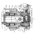
- Basic housing 1 of a tool changing device the machine fixed or arranged on a carriage may be, a housing shell 2 is arranged, the bearing 3, 4 for the storage of a total of 5 designated Hollow shaft is used at the right in the drawing End of a tool carrier 6 by means of screws 7 attached is.
- the tool carrier 6 is designed as a ring body and on a collar 8 of a flange 8a centered on a cylindrical part 9 of the total designated hollow shaft 5 is attached and thus forms part of the hollow shaft 5.
- the cylindrical one Part 9 of the hollow shaft 5 is interrupted approximately in the middle and by a composite of individual magnets Rotor 10 replaces the one electric Windings 11 exhibiting stator 12 surrounds the fixed is connected to the housing shell 2.
- This stator 12 together with the rotor 10 forms a ring motor with high torque. It is in his Inner diameter is formed so that it with the inner wall of the cylindrical part 9 of the hollow shaft 5 is aligned. Upon energization of the windings of the stator 12 of the Rotor 10 and thus the hollow shaft 5 driven. This one Hollow shaft 5 rotatably connected to the tool carrier 6 is, this is also due to the rotation the hollow shaft 5 pivoted.
- the interior of the hollow shaft 5 serves to accommodate a servomotor 13 which drives a with dash-dotted lines indicated tool 14th is provided on the outer circumference of the annular trained tool carrier 6 sits.
- a total of 15 designated Angular drive which has a central shaft 16, the vertical to the axis of the drive shaft 17 of the servomotor 13 through the center of the annular tool carrier 6 enclosed cavity 18 in the radial Direction runs.
- This central shaft 16 is in one Housing 19 mounted by means of ball bearings 20, the over Rolling 21 supported against the flange 8a is that forms part of the hollow shaft 5.
- the lower end of the central shaft 16 is a bevel gear 22 disposed with one on the drive shaft 17 seated bevel gear 23 meshes.
- a clutch 24 which with a corresponding trained end piece 25 of a tool shank 26 in the respective switching position of the tool carrier 6 is detachable.
- a coolant line 28 serves for the supply of coolant for the stator 12 of the ring motor.
- the electrical energy is supplied via a cable 29.
Landscapes
- Engineering & Computer Science (AREA)
- Mechanical Engineering (AREA)
- Turning (AREA)
- Manipulator (AREA)
- Cutting Tools, Boring Holders, And Turrets (AREA)
- Connection Of Motors, Electrical Generators, Mechanical Devices, And The Like (AREA)
Claims (11)
- Dispositif d'échange d'outil comportant un porte-outil s'appuyant en rotation, équipé d'au moins deux outils et qui peut pivoter au moyen d'une commande de pivotement électrique vers la position de travail respective pour un outil, le porte-outil étant relié de manière fixe en rotation à un arbre creux et s'appuyant en rotation par l'intermédiaire de cet arbre creux, un moteur annulaire servant de commande de pivotement s'engrenant directement sur l'arbre creux sans éléments de transmission de force mécaniques démultiplicateurs supplémentaires et l'arbre creux recevant au moins une pièce pour la commande et/ou au moins une pièce pour l'alimentation des outils, caractérisé en ce que, dans l'arbre creux (5), un moteur d'entraínement (13) pour les outils (14) est disposé.
- Dispositif d'échange d'outil selon la revendication 1, caractérisé en ce que la commande pour les outils (14) est un servomoteur (13).
- Dispositif d'échange d'outil selon la revendication 1 ou 2, caractérisé en ce qu'au moins une pièce de la chemise (9) de l'arbre creux (5) est constituée par un rotor (10) du moteur annulaire (10, 12).
- Dispositif d'échange d'outil selon la revendication 1 ou 2, caractérisé en ce qu'un rotor (10) du moteur annulaire (10, 12) est disposé sur la chemise (9) de l'arbre creux (5).
- Dispositif d'échange d'outil selon l'une quelconque des revendications 1 à 4, caractérisé en ce que le porte-outil (6) est positionnable par commande électrique du moteur annulaire (10, 12).
- Dispositif d'échange d'outil selon l'une quelconque des revendications 1 à 5, caractérisé en ce que le porte-outil (6) est réalisé sous forme d'un corps annulaire, que les outils (14) sont disposés dans le corps annulaire, qu'un dispositif de transmission de force (15) pouvant être couplé aux outils est disposé dans la cavité (18) circonscrite par le corps annulaire et que le dispositif de transmission de force (15) est en liaison avec la pièce (13) disposée dans l'arbre creux pour l'entraínement des outils (14).
- Dispositif d'échange d'outil selon la revendication 6, caractérisé en ce que le dispositif de transmission de force (15) est réalisé sous forme d'une commande orthogonale qui présente un arbre central (16) qui s'étend radialement à travers le centre de la cavité (18) circonscrite par le corps annulaire (6) et s'appuie dans une cage de roulements (19) s'appuyant en rotation par rapport à l'arbre creux (5), et qui supporte à une de ses extrémités une roue conique (22) s'empeignant avec une roue conique (23) entraínée par le servomoteur (13) et supporte à son autre extrémité un accouplement (24) qui sert à relier l'arbre central pouvant être entraíné (16) à tout outil pouvant être entraíné (14) du porte-outil (6).
- Dispositif d'échange d'outil selon l'une quelconque des revendications 1 à 7, caractérisé en ce qu'une pièce d'alimentation des outils (14) est constituée par au moins une conduite (27) d'alimentation en refroidisseur.
- Dispositif d'échange d'outil selon la revendication 8, caractérisé en ce que la conduite (27) d'alimentation des outils (14) est disposée dans une chemise (13a) du servomoteur (13) pour l'entraínement des outils.
- Dispositif d'échange d'outil selon la revendication 8, caractérisé en ce que la conduite (27) d'alimentation des outils (14) est disposée dans l'arbre (17) du servomoteur (13) pour l'entraínement des outils.
- Dispositif d'échange d'outil selon la revendication 8, caractérisé en ce que la conduite (27) d'alimentation des outils (14) est disposée entre une chemise (13a) du servomoteur (10) et l'arbre creux (5).
Applications Claiming Priority (2)
| Application Number | Priority Date | Filing Date | Title |
|---|---|---|---|
| DE19919553 | 1999-04-29 | ||
| DE19919553A DE19919553C5 (de) | 1999-04-29 | 1999-04-29 | Werkzeugwechselvorrichtung |
Publications (4)
| Publication Number | Publication Date |
|---|---|
| EP1048401A2 EP1048401A2 (fr) | 2000-11-02 |
| EP1048401A3 EP1048401A3 (fr) | 2002-06-19 |
| EP1048401B1 EP1048401B1 (fr) | 2003-06-25 |
| EP1048401B2 true EP1048401B2 (fr) | 2005-11-16 |
Family
ID=7906311
Family Applications (1)
| Application Number | Title | Priority Date | Filing Date |
|---|---|---|---|
| EP00107867A Expired - Lifetime EP1048401B2 (fr) | 1999-04-29 | 2000-04-12 | Dispositif de changement d'outils |
Country Status (4)
| Country | Link |
|---|---|
| US (1) | US6276035B1 (fr) |
| EP (1) | EP1048401B2 (fr) |
| BR (1) | BR0002065A (fr) |
| DE (2) | DE19919553C5 (fr) |
Cited By (2)
| Publication number | Priority date | Publication date | Assignee | Title |
|---|---|---|---|---|
| DE102007061793B3 (de) * | 2007-12-19 | 2009-02-26 | Emag Holding Gmbh | Werkzeugrevolver |
| DE102012108675A1 (de) | 2012-09-17 | 2014-03-20 | Chiron-Werke Gmbh & Co. Kg | Werkzeugmaschine zur Bearbeitung von Werkstücken und entsprechendes Verfahren |
Families Citing this family (9)
| Publication number | Priority date | Publication date | Assignee | Title |
|---|---|---|---|---|
| DE10125722A1 (de) * | 2001-05-18 | 2002-12-05 | Sauter Kg Feinmechanik | Werkzeugrevolver |
| DE10130446A1 (de) * | 2001-06-23 | 2003-01-09 | Sauter Kg Feinmechanik | Werkzeugrevolver |
| EP1744855B1 (fr) * | 2004-04-21 | 2008-01-16 | Starragheckert GmbH | Machine-outil |
| DE102005009893B4 (de) | 2005-03-01 | 2007-01-11 | Emag Holding Gmbh | Werkzeugmaschine mit mindestens einem Werkzeugrevolver |
| DE102007035030A1 (de) * | 2007-07-26 | 2009-01-29 | Sauter Feinmechanik Gmbh | Werkzeugrevolvereinheit für eine Werkzeugmaschine |
| US20090079279A1 (en) * | 2007-09-21 | 2009-03-26 | Fu-Yuan Cheng | Water Cooled Stator for a Direct Drive Torque Motor |
| EP2045036A1 (fr) * | 2007-10-04 | 2009-04-08 | Siemens Aktiengesellschaft | Dispositif de changement d'outil à l'aide d'un actionneur de levage à pivot à entraînement direct |
| DE102009022815B3 (de) * | 2009-05-27 | 2010-11-04 | Emag Holding Gmbh | Werkzeugrevolver mit angetriebenen Werkzeugen |
| JP6147623B2 (ja) * | 2013-09-17 | 2017-06-14 | 株式会社スギノマシン | タレット装置 |
Family Cites Families (18)
| Publication number | Priority date | Publication date | Assignee | Title |
|---|---|---|---|---|
| DE2128642C3 (de) * | 1971-06-09 | 1979-05-03 | Gildemeister Ag, 4800 Bielefeld | Werkzeugrevolveranordnung an Revolverdrehmaschinen |
| DE2741802A1 (de) * | 1977-09-16 | 1979-04-12 | Gerhard Stark | Revolverbohrmaschine |
| DE2921284A1 (de) * | 1979-05-25 | 1980-12-11 | Gildemeister Ag | Revolver fuer drehmaschinen |
| DE3133249A1 (de) * | 1981-08-22 | 1983-03-10 | Mannesmann AG, 4000 Düsseldorf | Antrieb fuer einen rotierenden bohrkopf einer vortriebsmaschine |
| DE3213172A1 (de) * | 1982-04-08 | 1983-10-13 | Bbc Brown Boveri & Cie | Formschlussloser elektromotorischer drehantrieb fuer waffenanlagen |
| DE3615784A1 (de) * | 1986-05-10 | 1987-11-12 | Bbc Brown Boveri & Cie | Permanenterregter gleichstrommotor |
| DD250481B1 (de) * | 1986-06-30 | 1990-07-04 | Werkzeugmasch Forschzent | Anordnung zum rundschalten und betreiben eines mehrfach-werkzeugtraegers |
| JPS6320130A (ja) * | 1986-07-11 | 1988-01-27 | Amada Co Ltd | プレス機械の金型回転装置 |
| DE3625218A1 (de) * | 1986-07-25 | 1988-02-04 | Index Werke Kg Hahn & Tessky | Hydraulikzuleitung fuer auf einem revolverkopf montierte werkzeughalte- oder greifvorrichtung |
| DE3730561C1 (de) * | 1987-09-11 | 1988-11-17 | Index Werke Kg Hahn & Tessky | Werkzeugrevolver |
| FR2629961B1 (fr) * | 1988-04-11 | 1993-11-12 | Acutronic France Sa | Dispositif d'entrainement en rotation d'un bras de centrifugeuse et procede d'alimentation en energie d'un tel dispositif |
| DE3817873A1 (de) * | 1988-05-26 | 1989-11-30 | Sauter Kg Feinmechanik | Werkzeugrevolver |
| DE3929136C1 (fr) * | 1989-09-01 | 1991-04-04 | Emag Maschinenfabrik Gmbh, 7335 Salach, De | |
| US5081762A (en) * | 1989-09-01 | 1992-01-21 | Brother Kogyo Kabushiki Kaisha | Tool exchange device for a machine tool |
| DE8915600U1 (de) * | 1989-09-14 | 1990-11-15 | Gildemeister Ag, 4800 Bielefeld | Werkzeugrevolver |
| JP2967651B2 (ja) * | 1991-08-12 | 1999-10-25 | ダイキン工業株式会社 | 位置割出装置 |
| US5632075A (en) * | 1995-03-09 | 1997-05-27 | Duplomatic S.R.L. | Tool-carrier turret |
| DE19516984C2 (de) * | 1995-05-09 | 1998-04-30 | Sauter Kg Feinmechanik | Werkzeugrevolver |
-
1999
- 1999-04-29 DE DE19919553A patent/DE19919553C5/de not_active Expired - Lifetime
-
2000
- 2000-04-12 EP EP00107867A patent/EP1048401B2/fr not_active Expired - Lifetime
- 2000-04-12 DE DE50002634T patent/DE50002634D1/de not_active Expired - Lifetime
- 2000-04-28 BR BR0002065-6A patent/BR0002065A/pt not_active IP Right Cessation
- 2000-04-28 US US09/562,215 patent/US6276035B1/en not_active Expired - Fee Related
Cited By (3)
| Publication number | Priority date | Publication date | Assignee | Title |
|---|---|---|---|---|
| DE102007061793B3 (de) * | 2007-12-19 | 2009-02-26 | Emag Holding Gmbh | Werkzeugrevolver |
| DE102012108675A1 (de) | 2012-09-17 | 2014-03-20 | Chiron-Werke Gmbh & Co. Kg | Werkzeugmaschine zur Bearbeitung von Werkstücken und entsprechendes Verfahren |
| DE102012108675B4 (de) * | 2012-09-17 | 2016-10-06 | Chiron-Werke Gmbh & Co. Kg | Werkzeugmaschine zur Bearbeitung von Werkstücken und entsprechendes Verfahren |
Also Published As
| Publication number | Publication date |
|---|---|
| DE50002634D1 (de) | 2003-07-31 |
| DE19919553A1 (de) | 2000-11-30 |
| US6276035B1 (en) | 2001-08-21 |
| DE19919553C2 (de) | 2001-03-29 |
| EP1048401B1 (fr) | 2003-06-25 |
| BR0002065A (pt) | 2000-10-31 |
| DE19919553C5 (de) | 2007-02-15 |
| EP1048401A3 (fr) | 2002-06-19 |
| EP1048401A2 (fr) | 2000-11-02 |
Similar Documents
| Publication | Publication Date | Title |
|---|---|---|
| EP1399293B2 (fr) | Machine-outil et tourelle porte-outils | |
| DE3416938A1 (de) | Kompaktes elektromechanisches stellglied | |
| EP0491894B1 (fr) | Entrainement de la broche principale d'une machine-outil | |
| DE202004021791U1 (de) | Maschine zum Ausrichten und Ausstatten von Gegenständen | |
| DE2624378A1 (de) | Vorrichtung zur bahnensteuerung von werkzeugen | |
| EP1817126B1 (fr) | Dispositif de serrage | |
| EP1048401B1 (fr) | Dispositif de changement d'outils | |
| DE2203586A1 (de) | Lagerung eines ein spinnorgan direkt antreibenden elektromotors | |
| DE10125722A1 (de) | Werkzeugrevolver | |
| EP3493370A1 (fr) | Dispositif d'entraînement ainsi que dispositif d'entraînement d'essieu pour un véhicule automobile | |
| WO2005118177A1 (fr) | Machine a decouper dotee d'un entrainement en rotation et en levage electrique | |
| EP0738591A1 (fr) | Cylindre de transfert avec une unité d'entraînement électrique | |
| DE4201849C2 (de) | Spindelantriebseinrichtung für Werkzeugmaschinen | |
| DE60122234T2 (de) | Schleifmaschine mit drehbarer Spindel mit Direktantrieb | |
| DE2244535A1 (de) | Kraftuebertragungsvorrichtung fuer eine mehrspindelwerkzeugmaschine | |
| DE10035718A1 (de) | Werkzeugmaschine | |
| DE69103676T2 (de) | Spindelantrieb. | |
| DE102008020313B4 (de) | Vorrichtung zum automatischen Werkzeug- oder Werkstückwechsel | |
| CH700946B1 (de) | Werkzeugrevolver. | |
| EP1300216B1 (fr) | Table à transfert circulaire avec entraînement direct et entraînement direct pour celle-ci | |
| DE3128228C2 (fr) | ||
| DE3815380A1 (de) | Drehbearbeitungseinrichtung fuer bohr- und fraesmaschinen | |
| EP2877314B1 (fr) | Dispositif de rotation d'une tête d'usinage au laser au moyen d'un moteur couple | |
| DE3727445C1 (en) | Arrangement for adjusting the jaws in power-operated chucks | |
| DE102009018317A1 (de) | Bremseinrichtung für eine Revolverkopf-Antriebskupplung |
Legal Events
| Date | Code | Title | Description |
|---|---|---|---|
| PUAI | Public reference made under article 153(3) epc to a published international application that has entered the european phase |
Free format text: ORIGINAL CODE: 0009012 |
|
| AK | Designated contracting states |
Kind code of ref document: A2 Designated state(s): AT BE CH CY DE DK ES FI FR GB GR IE IT LI LU MC NL PT SE |
|
| AX | Request for extension of the european patent |
Free format text: AL;LT;LV;MK;RO;SI |
|
| PUAL | Search report despatched |
Free format text: ORIGINAL CODE: 0009013 |
|
| RIC1 | Information provided on ipc code assigned before grant |
Free format text: 7B 23Q 39/02 A, 7B 23Q 5/28 B, 7B 23Q 1/00 B, 7B 23Q 3/155 B |
|
| AK | Designated contracting states |
Kind code of ref document: A3 Designated state(s): AT BE CH CY DE DK ES FI FR GB GR IE IT LI LU MC NL PT SE |
|
| AX | Request for extension of the european patent |
Free format text: AL;LT;LV;MK;RO;SI |
|
| 17P | Request for examination filed |
Effective date: 20020726 |
|
| GRAH | Despatch of communication of intention to grant a patent |
Free format text: ORIGINAL CODE: EPIDOS IGRA |
|
| AKX | Designation fees paid |
Designated state(s): DE FR IT |
|
| GRAH | Despatch of communication of intention to grant a patent |
Free format text: ORIGINAL CODE: EPIDOS IGRA |
|
| GRAA | (expected) grant |
Free format text: ORIGINAL CODE: 0009210 |
|
| AK | Designated contracting states |
Designated state(s): DE FR IT |
|
| REG | Reference to a national code |
Ref country code: IE Ref legal event code: FG4D Free format text: GERMAN |
|
| REF | Corresponds to: |
Ref document number: 50002634 Country of ref document: DE Date of ref document: 20030731 Kind code of ref document: P |
|
| REG | Reference to a national code |
Ref country code: IE Ref legal event code: FD4D |
|
| PLBQ | Unpublished change to opponent data |
Free format text: ORIGINAL CODE: EPIDOS OPPO |
|
| PLBI | Opposition filed |
Free format text: ORIGINAL CODE: 0009260 |
|
| PLBQ | Unpublished change to opponent data |
Free format text: ORIGINAL CODE: EPIDOS OPPO |
|
| PLBI | Opposition filed |
Free format text: ORIGINAL CODE: 0009260 |
|
| ET | Fr: translation filed | ||
| PLAX | Notice of opposition and request to file observation + time limit sent |
Free format text: ORIGINAL CODE: EPIDOSNOBS2 |
|
| 26 | Opposition filed |
Opponent name: GILDEMEISTER DREHMASCHINEN GMBH Effective date: 20040325 |
|
| 26 | Opposition filed |
Opponent name: INDEX-WERKE GMBH & CO. KG HAHN & TESSKY Effective date: 20040325 Opponent name: GILDEMEISTER DREHMASCHINEN GMBH Effective date: 20040325 |
|
| PLBB | Reply of patent proprietor to notice(s) of opposition received |
Free format text: ORIGINAL CODE: EPIDOSNOBS3 |
|
| PUAH | Patent maintained in amended form |
Free format text: ORIGINAL CODE: 0009272 |
|
| STAA | Information on the status of an ep patent application or granted ep patent |
Free format text: STATUS: PATENT MAINTAINED AS AMENDED |
|
| 27A | Patent maintained in amended form |
Effective date: 20051116 |
|
| AK | Designated contracting states |
Kind code of ref document: B2 Designated state(s): DE FR IT |
|
| REG | Reference to a national code |
Ref country code: ES Ref legal event code: FD2A Effective date: 20040413 |
|
| EN | Fr: translation not filed | ||
| REG | Reference to a national code |
Ref country code: FR Ref legal event code: CD |
|
| PG25 | Lapsed in a contracting state [announced via postgrant information from national office to epo] |
Ref country code: FR Free format text: LAPSE BECAUSE OF FAILURE TO SUBMIT A TRANSLATION OF THE DESCRIPTION OR TO PAY THE FEE WITHIN THE PRESCRIBED TIME-LIMIT Effective date: 20070105 |
|
| REG | Reference to a national code |
Ref country code: FR Ref legal event code: EERR Free format text: CORRECTION DE BOPI 07/01 - 3.2. |
|
| REG | Reference to a national code |
Ref country code: DE Ref legal event code: R082 Ref document number: 50002634 Country of ref document: DE Representative=s name: SCHIEBER - FARAGO, DE Ref country code: DE Ref legal event code: R082 Ref document number: 50002634 Country of ref document: DE Representative=s name: FARAGO PATENTANWAELTE, DE |
|
| REG | Reference to a national code |
Ref country code: FR Ref legal event code: PLFP Year of fee payment: 17 |
|
| PGFP | Annual fee paid to national office [announced via postgrant information from national office to epo] |
Ref country code: DE Payment date: 20160426 Year of fee payment: 17 |
|
| REG | Reference to a national code |
Ref country code: FR Ref legal event code: PLFP Year of fee payment: 18 |
|
| REG | Reference to a national code |
Ref country code: DE Ref legal event code: R119 Ref document number: 50002634 Country of ref document: DE |
|
| PG25 | Lapsed in a contracting state [announced via postgrant information from national office to epo] |
Ref country code: DE Free format text: LAPSE BECAUSE OF NON-PAYMENT OF DUE FEES Effective date: 20171103 |
|
| REG | Reference to a national code |
Ref country code: FR Ref legal event code: PLFP Year of fee payment: 19 |
|
| PGFP | Annual fee paid to national office [announced via postgrant information from national office to epo] |
Ref country code: FR Payment date: 20180426 Year of fee payment: 19 Ref country code: IT Payment date: 20180430 Year of fee payment: 19 |
|
| PG25 | Lapsed in a contracting state [announced via postgrant information from national office to epo] |
Ref country code: FR Free format text: LAPSE BECAUSE OF FAILURE TO SUBMIT A TRANSLATION OF THE DESCRIPTION OR TO PAY THE FEE WITHIN THE PRESCRIBED TIME-LIMIT Effective date: 20190430 |
|
| PG25 | Lapsed in a contracting state [announced via postgrant information from national office to epo] |
Ref country code: IT Free format text: LAPSE BECAUSE OF NON-PAYMENT OF DUE FEES Effective date: 20190412 |