EP1048420B1 - Kupplung für rotierendes Schneidwerkzeug - Google Patents
Kupplung für rotierendes Schneidwerkzeug Download PDFInfo
- Publication number
- EP1048420B1 EP1048420B1 EP20000303313 EP00303313A EP1048420B1 EP 1048420 B1 EP1048420 B1 EP 1048420B1 EP 20000303313 EP20000303313 EP 20000303313 EP 00303313 A EP00303313 A EP 00303313A EP 1048420 B1 EP1048420 B1 EP 1048420B1
- Authority
- EP
- European Patent Office
- Prior art keywords
- drive surface
- cutting tool
- arbor
- blade
- clamps
- Prior art date
- Legal status (The legal status is an assumption and is not a legal conclusion. Google has not performed a legal analysis and makes no representation as to the accuracy of the status listed.)
- Expired - Lifetime
Links
- 230000007246 mechanism Effects 0.000 title description 5
- 239000002184 metal Substances 0.000 claims abstract description 9
- 230000006835 compression Effects 0.000 description 2
- 238000007906 compression Methods 0.000 description 2
- 238000007792 addition Methods 0.000 description 1
- 230000004075 alteration Effects 0.000 description 1
- 239000013536 elastomeric material Substances 0.000 description 1
- 239000011435 rock Substances 0.000 description 1
Images



Classifications
-
- B—PERFORMING OPERATIONS; TRANSPORTING
- B27—WORKING OR PRESERVING WOOD OR SIMILAR MATERIAL; NAILING OR STAPLING MACHINES IN GENERAL
- B27B—SAWS FOR WOOD OR SIMILAR MATERIAL; COMPONENTS OR ACCESSORIES THEREFOR
- B27B5/00—Sawing machines working with circular or cylindrical saw blades; Components or equipment therefor
- B27B5/29—Details; Component parts; Accessories
- B27B5/30—Details; Component parts; Accessories for mounting or securing saw blades or saw spindles
- B27B5/32—Devices for securing circular saw blades to the saw spindle
-
- Y—GENERAL TAGGING OF NEW TECHNOLOGICAL DEVELOPMENTS; GENERAL TAGGING OF CROSS-SECTIONAL TECHNOLOGIES SPANNING OVER SEVERAL SECTIONS OF THE IPC; TECHNICAL SUBJECTS COVERED BY FORMER USPC CROSS-REFERENCE ART COLLECTIONS [XRACs] AND DIGESTS
- Y10—TECHNICAL SUBJECTS COVERED BY FORMER USPC
- Y10T—TECHNICAL SUBJECTS COVERED BY FORMER US CLASSIFICATION
- Y10T83/00—Cutting
- Y10T83/869—Means to drive or to guide tool
- Y10T83/8719—With transmission yieldable on overload
-
- Y—GENERAL TAGGING OF NEW TECHNOLOGICAL DEVELOPMENTS; GENERAL TAGGING OF CROSS-SECTIONAL TECHNOLOGIES SPANNING OVER SEVERAL SECTIONS OF THE IPC; TECHNICAL SUBJECTS COVERED BY FORMER USPC CROSS-REFERENCE ART COLLECTIONS [XRACs] AND DIGESTS
- Y10—TECHNICAL SUBJECTS COVERED BY FORMER USPC
- Y10T—TECHNICAL SUBJECTS COVERED BY FORMER US CLASSIFICATION
- Y10T83/00—Cutting
- Y10T83/929—Tool or tool with support
- Y10T83/9372—Rotatable type
- Y10T83/9377—Mounting of tool about rod-type shaft
- Y10T83/9379—At end of shaft
Definitions
- This invention relates generally to clutch mechanisms for tools, and particularly to a power tool according to the preambles of claims 1 and 4, to a rotatable cutting tool according to the preamble of claim 7 and to a device for mounting a cutting tool according to the preamble of claim 12.
- a device and a power tool according to the preamble of claim 1 are known from US3596446.
- a rotatable cutting tool and a power tool according to the preamble of claim 4 are known from US2978858.
- a blade clamp 24 may be disposed between the blade 10 and the shoulder 22.
- a second blade clamp 25 and/or a washer 46 may be disposed between blade 10 and nut 23. The blade 10 then rotates with the arbor 20 because of the clamping force.
- the blade 10 may stop rotational movement of arbor 20 when blade 10 gets caught by a workpiece. Such lack of movement may damage the motor or gears connecting the motor to arbor 20.
- United States Patent Serial No. 3 596 446 describes an adapter for yieldably connecting the blade of a rotary lawn mower to the drive shaft.
- the adapter comprises a pair of clutch plates, each having a plurality of teeth thereon, the faces being normally urged into engagement with each other so that the teeth mesh.
- One of the clutch plates is slidably mounted on the drive shaft and the other plate, to which the blade is attached, is rotatable with respect to the drive shaft when the two clutch plates are disengaged.
- the opposing faces of the two clutch plates are resiliently urged together forming a drive means for the blades.
- the resilient clutch connection allows the clutch plates to separate slightly permitting the drive shaft to continue rotating, although the blade itself remains stationary.
- a rotatable cutting tool according to claim 7.
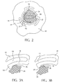
- FIG. 2 illustrates a first embodiment of the invention.
- Blade 10 is disposed on arbor 20, as in the prior art.
- first clamp 24 will be disposed between arbor 20 and blade 10 as in the prior art.
- a second clamp 25 (not shown) may also be used to clamp blade 10, as in the prior art.
- First clamp 24 may have at least one protrusion 26, which in turn may have a drive surface 27 contacting blade 10.
- drive surface 27 contacts a drive surface 12.
- Either drive surfaces 12, 27 or both may be inclined.
- Drive surface 12 may be disposed on a protrusion 13, which may be resiliently connected to blade 10 via a strip 14.
- Strip 14 is preferably made of metal.
- Blade 10 may also have a gap 15 between blade 10 and strip 14. Such gap 15 allows compression of protrusion 13.
- clamp 24 drives blade 10 because of the contact between drive surfaces 12, 27, as shown in FIG. 3A. If the blade 10 gets caught in a workpiece, drive surface 12 will slide along drive surface 27. Accordingly, protrusion 13 will be pushed towards gap 15, and thus compressed, allowing protrusion 26 to bypass protrusion 13. In other words, drive surface 27 will bypass drive surface 12. In this manner, arbor 20 may continue rotating without damage to the motor.
- protrusions 26 with drive surfaces 27 may be disposed on the arbor 20, the first clamp 24 and/or second clamp 25.
- protrusions 26 may be disposed on any combination of the arbor 20, and the first and second clamps 24, 25.
- more than one protrusion 26 may be provided thereon so that all protrusions 26 drive blade 10 simultaneously.
- protrusions 26 may be staggered so that a first set contact blade 10 at one time, and a second set contact blade 10 after the first set bypasses the protrusions 13 for the first time, etc.
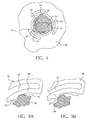
- FIGS. 5A and 5B The operation of such arrangement is illustrated in FIGS. 5A and 5B, and is similar to the operation of the first embodiment, as disclosed above and shown in FIGS. 3A and 3B.
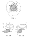
- FIGS. 6-7B illustrate a third embodiment of the invention, which operates in a similar way to the first embodiment. All the teachings of the first embodiment are incorporated by reference herein. Further like numerals refer to like parts.
- FIGS. 7A and 7B The operation of such arrangement is illustrated in FIGS. 7A and 7B, and is similar to the operation of the first embodiment, as disclosed above and shown in FIGS. 3A and 3B.
- FIG. 8 illustrates a fourth embodiment of the invention which operates in a similar way to the first embodiment. All the teachings of the first embodiment are incorporated by reference herein. Further like numerals refer to like parts.
- blade 10 is disposed on arbor 20, as in the prior art.
- first clamp 24 will be disposed between arbor 20 and blade 10 as in the prior art.
- a second clamp 25 (not shown) may also be used to clamp blade 10, as in the prior art.
- First clamp 24 may have at least one protrusion 31, which in turn may have a drive surface 33 contacting blade 10.
- drive surface 33 contacts a drive surface 41.
- Either drive surfaces 33, 41 or both may be inclined.
- Drive surface 41 may be disposed on a protrusion 40, which may be disposed on the periphery of the blade hole 11
- clamp 24 drives blade 10 because of the contact between drive surfaces 33, 41, as shown in FIG. 9A. If the blade 10 gets caught in a workpiece, drive surface 33 will slide along drive surface 41. Accordingly, protrusion 31 will be pushed towards gap 32, and thus compressed, allowing protrusion 40 to bypass protrusion 31. In other words, drive surface 41 will bypass drive surface 33. In this manner, arbor 20 may continue rotating without damage to the motor.
- protrusions 31 with drive surfaces 33 may be disposed on the arbor 20, the first clamp 24 and/or second clamp 25.
- protrusions 31 may be disposed on any combination of the arbor 20, and the first and second clamps 24, 25.
- more than one protrusion 31 may be provided thereon so that all protrusions 31 drive blade 10 simultaneously.
- protrusions 31 may be staggered so that a first set contact blade 10 at one time, and a second set contact blade 10 after the first set bypasses the protrusions 13 for the first time, etc.
- FIGS. 10-11B illustrate a fifth embodiment of the invention, which operates in a similar way to the second and fourth embodiments. All the teachings of the second and fourth embodiments are incorporated by reference herein. Further like numerals refer to like parts.
- protrusion 31 is no longer "floating" as in the fourth embodiment. Instead, a second strip 36 connects protrusion 31 to first clamp 24.
- Strip 36 is preferably made of metal. Further, strip 36 may resiliently connect protrusion 31 to first clamp 24.
- FIG. 12 illustrates a sixth embodiment of the invention which operates in a similar way to the first embodiment. All the teachings of the first embodiment incorporated by reference herein. Further like numerals refer to like parts.
- first clamp 24 will be disposed between arbor 20 and blade 10 as in the prior art.
- a second clamp 25 may also be used to clamp blade 10, as in the prior art.
- a nut 23 may be used to maintain all these elements on the arbour 20.
- First clamp 24 may have at least one detent mechanism 50, which in turn may comprise a detent 51 for engaging a recess 19 on blade 10.
- detent 51 is made of metal, and may have a rounded end which engages recess 19.
- Detent 51 may be biased towards recess 19 (and thus blade 10) by a spring 52.
Landscapes
- Life Sciences & Earth Sciences (AREA)
- Engineering & Computer Science (AREA)
- Mechanical Engineering (AREA)
- Wood Science & Technology (AREA)
- Forests & Forestry (AREA)
- Sawing (AREA)
- Cutting Tools, Boring Holders, And Turrets (AREA)
- Turning (AREA)
- Milling Processes (AREA)
Claims (16)
- Angetriebenes Werkzeug mit
einem Motor,
einer durch den Motor angetriebenen Welle (20, 21),
einem drehbaren Schneidwerkzeug (10), das an der Welle (20, 21) angeordnet ist und eine Drehachse hat, wobei das Schneidwerkzeug ferner eine Bohrung (11) aufweist, ersten (24) und zweiten (25) Spannelementen, die mit der Welle (20, 21) verbunden sind und das Schneidwerkzeug (10) einspannen,
wobei eines aus dem Schneidwerkzeug (10) und aus wenigstens einem aus dem ersten (24) und dem zweiten (25) Spannelement und der Welle (20, 21) eine erste Antriebsfläche (27, 41) zum Berühren einer zweiten Antriebsfläche (12, 33) an dem anderen aus dem Schneidwerkzeug (10) und aus dem wenigstens einen aus dem ersten (24) und dem zweiten (25) Spannelement und der Welle (20, 21) haben, wobei die zweite Antriebsfläche (12, 33) zwischen einer ersten Stellung, in der sie in Berührung mit der ersten Antriebsfläche (27, 41) ist, und einer zweiten Stellung bewegbar ist, in der sie die erste Antriebsfläche (27, 41) umgeht, wobei das angetriebene Werkzeug dadurch gekennzeichnet ist, dass sich die zweite Antriebsfläche entlang einer Richtung, die im Wesentlichen senkrecht zu der Drehachse ist, in die zweite Stellung bewegt. - Angetriebenes Werkzeug nach Anspruch 1, wobei die zweite Antriebsfläche (12, 33) elastisch mit dem anderen aus dem Schneidwerkzeug (10) und aus dem wenigstens einen aus dem ersten (24) und dem zweiten (25) Spannelement und der Welle (20, 21) verbunden ist.
- Angetriebenes Werkzeug nach einem der vorhergehenden Ansprüche, wobei wenigstens ein Metallstreifen (14, 16, 34, 36) die zweite Antriebsfläche (12, 33) mit dem anderen aus dem Schneidwerkzeug (10) und dem wenigstens einen aus dem ersten (24) und dem zweiten (25) Spannelement und der Welle (20, 21) verbindet.
- Angetriebenes Werkzeug mit
einem Motor,
einer durch den Motor angetriebenen Welle (20, 21), einem drehbaren Schneidwerkzeug (10), das an der Welle (20, 21) angeordnet ist und eine Drehachse hat, wobei das Schneidwerkzeug ferner eine Bohrung (11) aufweist,
wobei eines aus dem Schneidwerkzeug (10) und der Welle (20, 21) eine erste Antriebsfläche (27, 41) zum Berühren einer zweiten Antriebsfläche (12, 33) an dem anderen aus dem Schneidwerkzeug (10) und der Welle (20, 21) hat, wobei die zweite Antriebsfläche (12, 33) zwischen einer ersten Stellung, in der sie in Berührung mit der ersten Antriebsfläche (27, 41) ist, und einer zweiten Stellung bewegbar ist, in der sie die erste Antriebsfläche (27, 41) umgeht, wobei das angetriebene Werkzeug dadurch gekennzeichnet ist, dass sich die zweite Antriebsfläche entlang einer Richtung, die im Wesentlichen senkrecht zu der Drehachse ist, in die zweite Stellung bewegt. - Angetriebenes Werkzeug nach Anspruch 1, 2 oder 4, wobei die zweite Antriebsfläche ein Stift (51) ist und die erste Antriebsfläche eine Ausnehmung (19).
- Angetriebenes Werkzeug nach Anspruch 5, wobei eine Feder (52) den Stift (51) in die erste Stellung vorspannt.
- Drehbares Schneidwerkzeug (10) mit einer Drehachse, wobei das Schneidwerkzeug (10) umfasst:einen Hauptkörper (10) undeine erste Antriebsfläche (12), die mit dem Hauptkörper (10) zur Berührung einer zweiten Antriebsfläche (27) einer Befestigungseinrichtung (20, 21, 24, 25) verbunden ist,wobei die erste Antriebsfläche (12) zwischen einer ersten Stellung, in der sie in Berührung mit der zweiten Antriebsfläche (27) ist, und einer zweiten Stellung bewegbar ist, in der sie die zweite Antriebsfläche (27) umgeht, wobei das drehbare Schneidwerkzeug dadurch gekennzeichnet ist, dass sich die erste Antriebsfläche entlang einer Richtung, die im Wesentlichen senkrecht zu der Drehachse ist, in die zweite Stellung bewegt.
- Schneidwerkzeug (10) nach Anspruch 7, wobei die erste Antriebsfläche (12) elastisch mit dem Hauptkörper (10) verbunden ist.
- Schneidwerkzeug (10) nach Anspruch 7 oder 8, wobei wenigstens ein Metallstreifen (14, 16) die erste Antriebsfläche mit dem Hauptkörper (10) verbindet.
- Schneidwerkzeug (10) nach einem der Ansprüche 7 bis 9, wobei die erste Antriebsfläche ein Stift (51) ist und die zweite Antriebsfläche eine Ausnehmung (19).
- Schneidwerkzeug nach Anspruch 10, wobei eine Feder (52) den Stift (51) in die erste Stellung vorspannt.
- Einrichtung (20, 21, 24, 25) zum Befestigen eines Schneidwerkzeugs (10), wobei die Einrichtung umfasst:einen Hauptkörper (20, 21, 24, 25) undeine erste Antriebsfläche (33), die mit dem Hauptkörper (20, 21, 24, 25) zur Berührung einer zweiten Antriebsfläche (41) eines Schneidwerkzeugs (10) verbunden ist, die bewegbar zu dem Hauptkörper (20, 21, 24, 25) ist,wobei die erste Antriebsfläche (33) zwischen einer ersten Stellung, in der sie in Berührung mit der zweiten Antriebsfläche (41) ist, und einer zweiten Stellung bewegbar ist, in der sie die zweite Antriebsfläche (41) umgeht, wobei die Einrichtung dadurch gekennzeichnet ist, dass sich die erste Antriebsfläche entlang einer Richtung, die im Wesentlichen senkrecht zu der Drehachse ist, in die zweite Stellung bewegt.
- Einrichtung (20, 21, 24, 25) nach Anspruch 12, wobei die erste Antriebsfläche (33) elastisch mit dem Hauptkörper (20, 21, 24, 25) verbunden ist.
- Einrichtung (20, 21, 24, 25) nach Anspruch 13, wobei wenigstens ein Metallstreifen (34, 36) die erste Antriebsfläche (33) mit dem Hauptkörper (20, 21, 24, 25) verbindet.
- Einrichtung (20, 21, 24, 25) nach einem der Ansprüche 12, bis 14, wobei die erste Antriebsfläche ein Stift (51) ist und die zweite Antriebsfläche eine Ausnehmung (19).
- Einrichtung (20, 21, 24, 25) nach Anspruch 15, wobei eine Feder (52) den Stift (51) in die erste Stellung vorspannt.
Applications Claiming Priority (2)
| Application Number | Priority Date | Filing Date | Title |
|---|---|---|---|
| US09/294,036 US6439091B1 (en) | 1999-04-19 | 1999-04-19 | Clutch mechanism |
| US294036 | 1999-04-19 |
Publications (3)
| Publication Number | Publication Date |
|---|---|
| EP1048420A2 EP1048420A2 (de) | 2000-11-02 |
| EP1048420A3 EP1048420A3 (de) | 2003-10-29 |
| EP1048420B1 true EP1048420B1 (de) | 2007-04-18 |
Family
ID=23131622
Family Applications (1)
| Application Number | Title | Priority Date | Filing Date |
|---|---|---|---|
| EP20000303313 Expired - Lifetime EP1048420B1 (de) | 1999-04-19 | 2000-04-19 | Kupplung für rotierendes Schneidwerkzeug |
Country Status (8)
| Country | Link |
|---|---|
| US (1) | US6439091B1 (de) |
| EP (1) | EP1048420B1 (de) |
| CN (2) | CN1255238C (de) |
| AT (1) | ATE359900T1 (de) |
| DE (1) | DE60034395T2 (de) |
| DK (1) | DK1048420T3 (de) |
| ES (1) | ES2282079T3 (de) |
| PT (1) | PT1048420E (de) |
Families Citing this family (44)
| Publication number | Priority date | Publication date | Assignee | Title |
|---|---|---|---|---|
| DE10017980A1 (de) * | 2000-04-11 | 2001-10-25 | Bosch Gmbh Robert | Maschinenwerkzeugaufnahme |
| US7013987B2 (en) * | 2000-09-08 | 2006-03-21 | Black & Decker | Clutch assembly and clamp mechanism for rotary tool disc |
| US20090038904A1 (en) * | 2002-12-12 | 2009-02-12 | Bosk Brian K | Wedge clutch assembly |
| US20050139445A1 (en) * | 2002-12-12 | 2005-06-30 | Bosk Brian K. | Wedge clutch assembly |
| US20060135267A1 (en) * | 2002-12-12 | 2006-06-22 | Bosk Brian K | Wedge clutch assembly |
| US8439763B2 (en) * | 2002-12-12 | 2013-05-14 | Brian K. Bosk | Wedge clutch assembly |
| US6848998B2 (en) | 2002-12-12 | 2005-02-01 | Brian K. Bosk | Wedge clutch assembly |
| US7200982B2 (en) * | 2004-07-01 | 2007-04-10 | Briggs & Stratton Corporation | Blade slippage apparatus |
| CA2492257C (en) * | 2005-01-11 | 2011-01-25 | Venmar Ventilation Inc. | A damper assembly exploiting a crankshaft |
| EP1991398B1 (de) * | 2006-03-08 | 2011-01-19 | Premark FEG L.L.C. | Aufschnittmaschinenmesser |
| JP4847783B2 (ja) * | 2006-04-26 | 2011-12-28 | Hoya株式会社 | 内視鏡の湾曲操作装置 |
| US7954857B2 (en) * | 2006-04-27 | 2011-06-07 | Diba Industries, Inc. | Assembly of multi-use torque fitting and length of tubing having compressible seal |
| US20070254744A1 (en) * | 2006-04-27 | 2007-11-01 | Diba Industries, Inc. | Multi-use torque fitting |
| US7984933B2 (en) * | 2008-02-28 | 2011-07-26 | Diba Industries, Inc. | Multi-use torque fitting and compressible ferrule |
| US8230607B2 (en) | 2008-05-09 | 2012-07-31 | Milwaukee Electric Tool Corporation | Keyless blade clamp for a power tool |
| FR2938030B1 (fr) * | 2008-11-05 | 2011-11-25 | Valeo Embrayages | Dispositif de transmission de couple. |
| US20110044584A1 (en) * | 2009-08-19 | 2011-02-24 | Diba Industries, Inc. | Optical fiber connection assembly |
| CH703182A1 (de) * | 2010-05-26 | 2011-11-30 | Berner Fachhochschule Biel Architektur Holz Und Bau | Einrichtung zum Zentrieren von Kreissägeblättern und ähnlichen Werkzeugen auf der Welle. |
| CN102324662A (zh) * | 2011-06-13 | 2012-01-18 | 人和光伏科技有限公司 | 卡扣连接装置 |
| US8857066B2 (en) * | 2011-08-22 | 2014-10-14 | Robert Bosch Gmbh | Power saw including an impact mechanism |
| CN102430799A (zh) * | 2011-09-08 | 2012-05-02 | 中国人民解放军第四军医大学 | 一种电子专业多用途微型电切锯 |
| CN104428110A (zh) * | 2012-04-30 | 2015-03-18 | Gea食品策划德国股份有限公司 | 包含保护腔体的切削片 |
| FR3000155B1 (fr) | 2012-12-21 | 2015-09-25 | Valeo Embrayages | Amortisseur de torsion pour un dispositif de transmission de couple d'un vehicule automobile |
| PT3077144T (pt) * | 2013-12-02 | 2020-03-31 | Rosjoh Pty Ltd | Aparelho para reter ferramentas de corte em máquinas |
| FR3024759B1 (fr) | 2014-08-08 | 2020-01-03 | Valeo Embrayages | Amortisseur, notamment pour un embrayage d'automobile |
| US9850995B2 (en) | 2015-10-02 | 2017-12-26 | Valeo Embrayages | Hydrokinetic torque coupling device for a motor vehicle |
| US9822862B2 (en) | 2015-10-02 | 2017-11-21 | Valeo Embrayages | Hydrokinetic torque coupling device for a motor vehicle |
| US10030753B2 (en) | 2015-10-02 | 2018-07-24 | Valeo Embrayages | Hydrokinetic torque coupling device for a motor vehicle |
| US10161492B2 (en) | 2015-10-02 | 2018-12-25 | Valeo Embrayages | Hydrokinetic torque coupling device for motor vehicle |
| US9885406B2 (en) | 2015-10-02 | 2018-02-06 | Valeo Embrayages | Hydrokinetic torque coupling device for a motor vehicle |
| US9989135B2 (en) | 2015-10-02 | 2018-06-05 | Valeo Embrayages | Hydrokinetic torque coupling device for a motor vehicle |
| US10288144B2 (en) | 2016-02-11 | 2019-05-14 | Valeo Embrayages | Transmission torque converter device |
| CN105772859B (zh) * | 2016-04-25 | 2018-03-06 | 浙江百金机床制造有限公司 | 一种回转式护锯片机构 |
| US10234007B2 (en) | 2016-05-23 | 2019-03-19 | Valeo Embrayages | Hydrokinetic torque coupling device for motor vehicle |
| US10054209B2 (en) | 2016-06-20 | 2018-08-21 | Valeo Embrayages | Torque transmitting device |
| US10100909B2 (en) | 2016-06-21 | 2018-10-16 | Valeo Embrayages | Torque transmission device for motor vehicle |
| US9903456B1 (en) | 2016-08-24 | 2018-02-27 | Valeo Embrayages | Torque converter with lock-up clutch bias spring |
| US10094458B2 (en) | 2016-08-24 | 2018-10-09 | Valeo Embrayages | Torque transmitting device |
| US10113624B2 (en) | 2016-11-17 | 2018-10-30 | Valeo Embrayages | Torsional vibration damper and lock-up clutch for hydrokinetic torque-coupling device, and method for making the same |
| US10107372B2 (en) | 2016-11-22 | 2018-10-23 | Valeo Embrayages | Torsional vibration damper and lock-up clutch for hydrokinetic torque-coupling device, and method for making the same |
| CN106671204A (zh) * | 2017-03-01 | 2017-05-17 | 孔令寿 | 木工锯、铣一体机 |
| US10094460B1 (en) | 2017-04-06 | 2018-10-09 | Valeo Embrayages | Vibration damper and lock-up clutch for hydrokinetic torque-coupling device, and method for making the same |
| DE102019206810A1 (de) * | 2018-05-31 | 2019-12-05 | Bosch Limited | Eine Halteanordnung für ein Kreissägewerkzeug |
| CN108555386A (zh) * | 2018-06-22 | 2018-09-21 | 廊坊盛森磨具有限公司 | 一种装夹装置 |
Family Cites Families (36)
| Publication number | Priority date | Publication date | Assignee | Title |
|---|---|---|---|---|
| US1548427A (en) * | 1920-06-21 | 1925-08-04 | Nat Lock Co | Overload-release clutch |
| US1518634A (en) * | 1923-06-29 | 1924-12-09 | Jr Dick Kendall Cason | Safety clutch for drill stems |
| US1865559A (en) * | 1930-02-21 | 1932-07-05 | Montgrand Leon De | Mechanical coupling |
| US2028441A (en) * | 1932-07-14 | 1936-01-21 | Black & Decker Mfg Co | Clutch release for portable electric wrenches |
| US2256496A (en) * | 1940-09-27 | 1941-09-23 | Girard C Robinson | Power driven tool |
| US2491976A (en) * | 1946-01-17 | 1949-12-20 | Edward C Hauser | Detachable wheel |
| US2637987A (en) * | 1947-02-18 | 1953-05-12 | Hil Jon Safety Crown Corp | Overload release coupling |
| US2519848A (en) * | 1947-03-27 | 1950-08-22 | Ragnar K Osterdahl | Power transmission mechanism |
| US2572042A (en) * | 1948-07-13 | 1951-10-23 | Charles A Martin | Means for mounting cutting blades on shafts |
| US2729038A (en) * | 1953-10-30 | 1956-01-03 | Alma A Hutchins | Rotary abrading machine heads |
| US2803103A (en) * | 1955-09-14 | 1957-08-20 | Oscar G Kollman | Drive shaft connection assembly for rotary power mower |
| US2978858A (en) * | 1958-07-08 | 1961-04-11 | Warren E Moody | Yieldable drive connection for a rotary lawn mower |
| US3561543A (en) * | 1969-02-07 | 1971-02-09 | Ingersoll Rand Co | Rotary impact wrench mechanism |
| US3596446A (en) * | 1969-03-06 | 1971-08-03 | Sidney C Whiteheart | Adapter for yieldably connecting the blade of a rotary lawn mower to the drive shaft |
| JPS5131333Y2 (de) * | 1971-09-30 | 1976-08-06 | ||
| US4053980A (en) * | 1976-09-16 | 1977-10-18 | Outboard Marine Corporation | Chain saw including an overtorque releasing clutch |
| US4205572A (en) * | 1978-08-29 | 1980-06-03 | Weiner Robert I | Saw blade retainer and kickback clutch assembly |
| DE2941358A1 (de) * | 1979-10-12 | 1981-04-23 | Robert Bosch Gmbh, 7000 Stuttgart | Befestigungsvorrichtung fuer ein kreissaegeblatt auf einem antriebszapfen |
| FR2499181B1 (fr) * | 1981-02-04 | 1986-03-28 | Valeo | Dispositif amortisseur de torsion, en particulier friction d'embrayage, notamment pour vehicule automobile |
| US4766641A (en) * | 1985-12-31 | 1988-08-30 | Whirlpool Corporation | Detent clutch for a vacuum cleaner |
| DE3705638C1 (de) * | 1987-02-21 | 1988-09-08 | Bosch Gmbh Robert | Spanneinrichtung zum axialen Festspannen eines scheibenfoermigen Werkzeuges,insbesondere einer Schleifscheibe,an einem Flansch einer angetriebenen Spindel |
| US4991473A (en) * | 1987-06-19 | 1991-02-12 | Franklin S. Sax | Rotating driver with automatic speed switching and torque limiting controls |
| US5000721A (en) * | 1987-08-20 | 1991-03-19 | Itt Corporation | Clutch apparatus |
| DE3827840A1 (de) * | 1988-08-17 | 1990-02-22 | Gardner Denver Gmbh | Kraftbetriebenes werkzeug, vorzugsweise schrauber |
| US5293798A (en) * | 1989-03-07 | 1994-03-15 | Taihei Machinery Works, Inc. | Sawing machine |
| US5099970A (en) * | 1991-05-10 | 1992-03-31 | Diebel Manufacturing Company | Torque-limiting clutch brake assembly |
| US5303688A (en) * | 1992-04-03 | 1994-04-19 | Chiuminatta Edward R | Mounting arbor for saw cutting blades |
| WO1994013964A1 (en) * | 1992-12-10 | 1994-06-23 | Norman Leslie Matthews | Improved fastener |
| CA2092219A1 (en) * | 1993-03-23 | 1994-09-24 | Tomo Bonac | Arbour clip for saws |
| JPH0727121A (ja) * | 1993-06-30 | 1995-01-27 | Jacobs Japan Inc | 締付け用ネジ |
| US5477845A (en) * | 1994-08-12 | 1995-12-26 | Zuzelo; Edward A. | Saw blade and mounting means for the same |
| US5566458A (en) * | 1994-12-13 | 1996-10-22 | Milwaukee Electric Tool Corporation | Clutch mechanism for reciprocating saws |
| US5871322A (en) * | 1994-12-22 | 1999-02-16 | Power Tool Holders Incorporated | Clamp screw |
| DE19509147C1 (de) * | 1995-03-14 | 1996-05-23 | Atlas Copco Elektrowerkzeuge | Spanneinrichtung zum Festlegen eines scheibenförmigen Werkzeugs |
| DE29508308U1 (de) * | 1995-05-19 | 1995-08-24 | Galeski, Peter, 56457 Westerburg | Bearbeitungsvorrichtung für Steinplatten |
| AU3530497A (en) * | 1996-12-05 | 1998-06-11 | Power Tool Holders Incorporated | Improved ball screw clamping device |
-
1999
- 1999-04-19 US US09/294,036 patent/US6439091B1/en not_active Expired - Fee Related
-
2000
- 2000-04-11 CN CNB001064622A patent/CN1255238C/zh not_active Expired - Fee Related
- 2000-04-11 CN CNA2006100678744A patent/CN101032771A/zh active Pending
- 2000-04-19 AT AT00303313T patent/ATE359900T1/de not_active IP Right Cessation
- 2000-04-19 PT PT00303313T patent/PT1048420E/pt unknown
- 2000-04-19 ES ES00303313T patent/ES2282079T3/es not_active Expired - Lifetime
- 2000-04-19 DE DE2000634395 patent/DE60034395T2/de not_active Expired - Lifetime
- 2000-04-19 EP EP20000303313 patent/EP1048420B1/de not_active Expired - Lifetime
- 2000-04-19 DK DK00303313T patent/DK1048420T3/da active
Also Published As
| Publication number | Publication date |
|---|---|
| ES2282079T3 (es) | 2007-10-16 |
| PT1048420E (pt) | 2007-07-27 |
| DE60034395D1 (de) | 2007-05-31 |
| EP1048420A3 (de) | 2003-10-29 |
| CN1270867A (zh) | 2000-10-25 |
| DE60034395T2 (de) | 2008-01-03 |
| CN101032771A (zh) | 2007-09-12 |
| CN1255238C (zh) | 2006-05-10 |
| US6439091B1 (en) | 2002-08-27 |
| DK1048420T3 (da) | 2007-08-27 |
| ATE359900T1 (de) | 2007-05-15 |
| EP1048420A2 (de) | 2000-11-02 |
Similar Documents
| Publication | Publication Date | Title |
|---|---|---|
| EP1048420B1 (de) | Kupplung für rotierendes Schneidwerkzeug | |
| EP1339528B1 (de) | Handwerkzeugmaschine mit sensor zur signalgebung beim wechseln des einsatzwerkzeugs | |
| US6702090B2 (en) | Power tool and spindle lock system | |
| US7063201B2 (en) | Power tool and spindle lock system | |
| US6474206B1 (en) | Miter saw with wear plates and orientation system therefor | |
| EP0633830B1 (de) | Spindel zum festspannen von kreissägeblättern | |
| EP1414620B1 (de) | System mit einer werkzeugaufnahme | |
| EP1240983B1 (de) | Handwerkzeugmaschine mit Arretierungssystem der Spindel | |
| EP1250989B1 (de) | Kupplungsanordnung für rotierendes scheibenförmiges Werkzeug | |
| US6148526A (en) | Manually driven machine | |
| EP1704023B1 (de) | Drehwellenverriegelungsmechanismus | |
| AU2022287546B2 (en) | Work tool and transmission system thereof | |
| US5346342A (en) | Shaft lock arrangment for a power tool | |
| US5140754A (en) | Power tool protective hood positioning system and method of manufacturing the same | |
| EP0810050B1 (de) | Sägeblattaufspannvorrichtung für ein motorisiertes Werkzeug | |
| CA2290178A1 (en) | Saw blade and mounting device for the same | |
| GB2171343A (en) | Ratchet system in hand-held tool | |
| EP0213172B1 (de) | Zurückfederndes schutzblech für scheibenmesserwerkzeuge | |
| CA3011109A1 (en) | Power tool including power tool base couplable with power tool implements | |
| EP1211027A2 (de) | Spanneinrichtung für scheibenförmiges Bearbeitungswerkzeug | |
| EP0875347B1 (de) | Schutzhaube und Steuergeräte für eine Kapp- und Gehrungssäge | |
| DE212017000224U1 (de) | Elektrisch angetriebenes Werkzeug | |
| EP3150333B1 (de) | Elektrohandwerkzeug mit einer verbesserten bremsanordnung | |
| CN115338696B (zh) | 刀具及打磨装置 | |
| AU2021441323B2 (en) | Force amplified fastener for power tool implements |
Legal Events
| Date | Code | Title | Description |
|---|---|---|---|
| PUAI | Public reference made under article 153(3) epc to a published international application that has entered the european phase |
Free format text: ORIGINAL CODE: 0009012 |
|
| AK | Designated contracting states |
Kind code of ref document: A2 Designated state(s): AT BE CH CY DE DK ES FI FR GB GR IE IT LI LU MC NL PT SE |
|
| AX | Request for extension of the european patent |
Free format text: AL;LT;LV;MK;RO;SI |
|
| PUAL | Search report despatched |
Free format text: ORIGINAL CODE: 0009013 |
|
| AK | Designated contracting states |
Kind code of ref document: A3 Designated state(s): AT BE CH CY DE DK ES FI FR GB GR IE IT LI LU MC NL PT SE |
|
| AX | Request for extension of the european patent |
Extension state: AL LT LV MK RO SI |
|
| RIC1 | Information provided on ipc code assigned before grant |
Ipc: 7B 27B 5/32 A Ipc: 7B 24B 45/00 B |
|
| 17P | Request for examination filed |
Effective date: 20031204 |
|
| 17Q | First examination report despatched |
Effective date: 20040203 |
|
| AKX | Designation fees paid |
Designated state(s): AT BE CH CY DE DK ES FI FR GB GR IE IT LI LU MC NL PT SE |
|
| GRAP | Despatch of communication of intention to grant a patent |
Free format text: ORIGINAL CODE: EPIDOSNIGR1 |
|
| GRAS | Grant fee paid |
Free format text: ORIGINAL CODE: EPIDOSNIGR3 |
|
| GRAA | (expected) grant |
Free format text: ORIGINAL CODE: 0009210 |
|
| AK | Designated contracting states |
Kind code of ref document: B1 Designated state(s): AT BE CH CY DE DK ES FI FR GB GR IE IT LI LU MC NL PT SE |
|
| REG | Reference to a national code |
Ref country code: CH Ref legal event code: EP |
|
| REG | Reference to a national code |
Ref country code: IE Ref legal event code: FG4D |
|
| REF | Corresponds to: |
Ref document number: 60034395 Country of ref document: DE Date of ref document: 20070531 Kind code of ref document: P |
|
| REG | Reference to a national code |
Ref country code: PT Ref legal event code: SC4A Free format text: AVAILABILITY OF NATIONAL TRANSLATION Effective date: 20070717 |
|
| REG | Reference to a national code |
Ref country code: SE Ref legal event code: TRGR |
|
| REG | Reference to a national code |
Ref country code: CH Ref legal event code: NV Representative=s name: E. BLUM & CO. AG PATENT- UND MARKENANWAELTE VSP |
|
| REG | Reference to a national code |
Ref country code: DK Ref legal event code: T3 |
|
| ET | Fr: translation filed | ||
| REG | Reference to a national code |
Ref country code: ES Ref legal event code: FG2A Ref document number: 2282079 Country of ref document: ES Kind code of ref document: T3 |
|
| PLBE | No opposition filed within time limit |
Free format text: ORIGINAL CODE: 0009261 |
|
| STAA | Information on the status of an ep patent application or granted ep patent |
Free format text: STATUS: NO OPPOSITION FILED WITHIN TIME LIMIT |
|
| 26N | No opposition filed |
Effective date: 20080121 |
|
| PG25 | Lapsed in a contracting state [announced via postgrant information from national office to epo] |
Ref country code: GR Free format text: LAPSE BECAUSE OF FAILURE TO SUBMIT A TRANSLATION OF THE DESCRIPTION OR TO PAY THE FEE WITHIN THE PRESCRIBED TIME-LIMIT Effective date: 20070719 |
|
| PG25 | Lapsed in a contracting state [announced via postgrant information from national office to epo] |
Ref country code: IE Free format text: LAPSE BECAUSE OF NON-PAYMENT OF DUE FEES Effective date: 20070419 |
|
| PG25 | Lapsed in a contracting state [announced via postgrant information from national office to epo] |
Ref country code: MC Free format text: LAPSE BECAUSE OF NON-PAYMENT OF DUE FEES Effective date: 20070430 |
|
| PG25 | Lapsed in a contracting state [announced via postgrant information from national office to epo] |
Ref country code: CY Free format text: LAPSE BECAUSE OF FAILURE TO SUBMIT A TRANSLATION OF THE DESCRIPTION OR TO PAY THE FEE WITHIN THE PRESCRIBED TIME-LIMIT Effective date: 20070418 |
|
| PGFP | Annual fee paid to national office [announced via postgrant information from national office to epo] |
Ref country code: ES Payment date: 20090427 Year of fee payment: 10 |
|
| PG25 | Lapsed in a contracting state [announced via postgrant information from national office to epo] |
Ref country code: LU Free format text: LAPSE BECAUSE OF NON-PAYMENT OF DUE FEES Effective date: 20070419 |
|
| PGFP | Annual fee paid to national office [announced via postgrant information from national office to epo] |
Ref country code: AT Payment date: 20090401 Year of fee payment: 10 Ref country code: NL Payment date: 20090423 Year of fee payment: 10 Ref country code: PT Payment date: 20090406 Year of fee payment: 10 |
|
| PGFP | Annual fee paid to national office [announced via postgrant information from national office to epo] |
Ref country code: CH Payment date: 20090427 Year of fee payment: 10 |
|
| REG | Reference to a national code |
Ref country code: NL Ref legal event code: V1 Effective date: 20101101 |
|
| REG | Reference to a national code |
Ref country code: CH Ref legal event code: PL |
|
| PG25 | Lapsed in a contracting state [announced via postgrant information from national office to epo] |
Ref country code: NL Free format text: LAPSE BECAUSE OF NON-PAYMENT OF DUE FEES Effective date: 20101101 Ref country code: AT Free format text: LAPSE BECAUSE OF NON-PAYMENT OF DUE FEES Effective date: 20100419 |
|
| PG25 | Lapsed in a contracting state [announced via postgrant information from national office to epo] |
Ref country code: CH Free format text: LAPSE BECAUSE OF NON-PAYMENT OF DUE FEES Effective date: 20100430 Ref country code: PT Free format text: LAPSE BECAUSE OF NON-PAYMENT OF DUE FEES Effective date: 20101019 Ref country code: LI Free format text: LAPSE BECAUSE OF NON-PAYMENT OF DUE FEES Effective date: 20100430 |
|
| REG | Reference to a national code |
Ref country code: ES Ref legal event code: FD2A Effective date: 20111118 |
|
| PG25 | Lapsed in a contracting state [announced via postgrant information from national office to epo] |
Ref country code: ES Free format text: LAPSE BECAUSE OF NON-PAYMENT OF DUE FEES Effective date: 20100420 |
|
| PGFP | Annual fee paid to national office [announced via postgrant information from national office to epo] |
Ref country code: BE Payment date: 20120426 Year of fee payment: 13 Ref country code: DK Payment date: 20120425 Year of fee payment: 13 |
|
| PGFP | Annual fee paid to national office [announced via postgrant information from national office to epo] |
Ref country code: FI Payment date: 20120427 Year of fee payment: 13 Ref country code: FR Payment date: 20120503 Year of fee payment: 13 |
|
| PGFP | Annual fee paid to national office [announced via postgrant information from national office to epo] |
Ref country code: IT Payment date: 20120423 Year of fee payment: 13 |
|
| PGFP | Annual fee paid to national office [announced via postgrant information from national office to epo] |
Ref country code: GB Payment date: 20130429 Year of fee payment: 14 Ref country code: DE Payment date: 20130429 Year of fee payment: 14 Ref country code: SE Payment date: 20130429 Year of fee payment: 14 |
|
| BERE | Be: lapsed |
Owner name: BLACK & DECKER INC. Effective date: 20130430 |
|
| REG | Reference to a national code |
Ref country code: DK Ref legal event code: EBP Effective date: 20130430 |
|
| PG25 | Lapsed in a contracting state [announced via postgrant information from national office to epo] |
Ref country code: BE Free format text: LAPSE BECAUSE OF NON-PAYMENT OF DUE FEES Effective date: 20130430 |
|
| REG | Reference to a national code |
Ref country code: FR Ref legal event code: ST Effective date: 20131231 |
|
| PG25 | Lapsed in a contracting state [announced via postgrant information from national office to epo] |
Ref country code: FI Free format text: LAPSE BECAUSE OF NON-PAYMENT OF DUE FEES Effective date: 20130419 Ref country code: FR Free format text: LAPSE BECAUSE OF NON-PAYMENT OF DUE FEES Effective date: 20130430 Ref country code: IT Free format text: LAPSE BECAUSE OF NON-PAYMENT OF DUE FEES Effective date: 20130419 |
|
| PG25 | Lapsed in a contracting state [announced via postgrant information from national office to epo] |
Ref country code: DK Free format text: LAPSE BECAUSE OF NON-PAYMENT OF DUE FEES Effective date: 20130430 |
|
| REG | Reference to a national code |
Ref country code: DE Ref legal event code: R119 Ref document number: 60034395 Country of ref document: DE |
|
| REG | Reference to a national code |
Ref country code: SE Ref legal event code: EUG |
|
| GBPC | Gb: european patent ceased through non-payment of renewal fee |
Effective date: 20140419 |
|
| REG | Reference to a national code |
Ref country code: DE Ref legal event code: R119 Ref document number: 60034395 Country of ref document: DE Effective date: 20141101 |
|
| PG25 | Lapsed in a contracting state [announced via postgrant information from national office to epo] |
Ref country code: DE Free format text: LAPSE BECAUSE OF NON-PAYMENT OF DUE FEES Effective date: 20141101 Ref country code: GB Free format text: LAPSE BECAUSE OF NON-PAYMENT OF DUE FEES Effective date: 20140419 Ref country code: SE Free format text: LAPSE BECAUSE OF NON-PAYMENT OF DUE FEES Effective date: 20140420 |