EP1048449A1 - Schachttür für eine Ballenpresse vertikaler Bauart - Google Patents
Schachttür für eine Ballenpresse vertikaler Bauart Download PDFInfo
- Publication number
- EP1048449A1 EP1048449A1 EP99108132A EP99108132A EP1048449A1 EP 1048449 A1 EP1048449 A1 EP 1048449A1 EP 99108132 A EP99108132 A EP 99108132A EP 99108132 A EP99108132 A EP 99108132A EP 1048449 A1 EP1048449 A1 EP 1048449A1
- Authority
- EP
- European Patent Office
- Prior art keywords
- door
- shaft door
- shaft
- press
- landing
- Prior art date
- Legal status (The legal status is an assumption and is not a legal conclusion. Google has not performed a legal analysis and makes no representation as to the accuracy of the status listed.)
- Granted
Links
- 239000000945 filler Substances 0.000 claims description 20
- 239000002699 waste material Substances 0.000 claims 1
- 239000000463 material Substances 0.000 description 4
- 238000005253 cladding Methods 0.000 description 2
- 238000009434 installation Methods 0.000 description 2
- 125000006850 spacer group Chemical group 0.000 description 2
- 239000000126 substance Substances 0.000 description 2
- 239000000725 suspension Substances 0.000 description 2
- 230000007704 transition Effects 0.000 description 2
- 235000014676 Phragmites communis Nutrition 0.000 description 1
- 230000001939 inductive effect Effects 0.000 description 1
- 238000005096 rolling process Methods 0.000 description 1
Images


Classifications
-
- B—PERFORMING OPERATIONS; TRANSPORTING
- B30—PRESSES
- B30B—PRESSES IN GENERAL
- B30B9/00—Presses specially adapted for particular purposes
- B30B9/30—Presses specially adapted for particular purposes for baling; Compression boxes therefor
- B30B9/3003—Details
- B30B9/3032—Press boxes
Definitions
- the present invention relates to a shaft door for a Baler, according to the preamble of claim 1 and one Baler with such a shaft door.
- a baler is known from DE 297 042 76 01, which a press shaft door and one above it Has filler opening, which with the help of a Filler shaft door is lockable.
- the hopper door is attached to the press housing above the press shaft door Guide rails slidably guided so that they can be opened the feed chute opening can be moved up.
- the guide rails extend over the lid of the Press housing upwards, so that this known Baler always requires such a parking space when which has enough space above the baler.
- the one designed as a sliding door offers Filling shaft door of this baler has the advantage that none What is there, the feed shaft door can be swung away to the front when filling the substances to be compressed into the Filling chute can be disruptive.
- baler Whenever there is little space to set up a baler is available, it is necessary, especially the To keep the overall height of the baler as low as possible.
- a shaft door for a Baling press consisting of a press shaft door with a above this intended filler opening and one Filling shaft door, by means of which the filling shaft opening is closable, such that the Press shaft door a guide device is provided with whose help the feed shaft door substantially parallel to Door level of the press shaft door between a closed Position and an open position is slidable the hopper door completely in the open position to lie within the external dimensions of the press shaft door is coming.
- the filling shaft door designed as a sliding door is So to close the feed chute opening from below pushed up.
- the shaft door according to the invention has the advantage that the Position of the baler neither wider nor higher than that corresponding outer dimensions of the press housing, which in essentially the width or height of the press shaft door accordingly, must be.
- the filling shaft door In the fully open position the filling shaft door is below the Filling shaft opening on the outside of the press shaft door. Since the filler shaft door does not swing forward, but instead Moved down, handling becomes too not compressing substances immediately before the baler hampered by a feed door that protrudes too far.
- what is in the baler Material when closing the filler door pinched and while closing in the interior of the Press pushed.
- the filling shaft door in the open position is located indirectly in front of the press shaft door and the top edge of the hopper door roughly on the same
- a work table formed the depth of which is essentially the sum of the Thicknesses of the feed shaft door and the press shaft door corresponds.
- a work table formed in this way is added not so far from the front of the baler emerges, such as a pivoted away by 90 ° about a horizontal axis Filler shaft door.
- the guide device for the hopper door exists preferably from two guideway units, each of which running vertically in the lateral outer areas of the Press shaft door are arranged.
- the hopper door instructs at least one of each of their side faces Track body on the in a track of the respective Guideway unit is guided.
- the tracking bodies are located itself in the upper area of the filling shaft door and the Guideway has such a course that the Filling shaft door forward by one dimension during opening which is slightly larger than the largest Feeder door thickness.
- the loading shaft door can be in the closed position at least with parts of your lower edge on the upper edge of the Filling chute opening and thus in the latter being held.
- the hopper door but not only in its upper area, but also in led her lower range. You can do two more Guideways are provided in which two more Track body are guided. These other tracking bodies are arranged in the lower area of the hopper door can be located within the two guideway units Support vertically so that the feed shaft door is supported not required on the upper edge of the feed chute opening is.
- Each guideway unit can consist of three separate ones Guideway bodies exist, the geometry of which Guideways for the upper and lower areas arranged tracking body of the hopper door specifies.
- the guideway units can also be in one piece be designed so that the guideways are not only through Assembly of the individual guideway bodies on the press shaft door arise.
- the lowest guideway body in its lower area Stop on opening the hopper door in the Holds position. Is the fill shaft door in the closed position not on the lower edge of the Filler opening, so the bottom Guide body in its upper area with be provided with a stop that the filling shaft door in holds the closed position.
- the guideway leading the respective upper track body extends directly to the outside of the Press shaft door approach so that the area there Press shaft door a stop for the upper one Forms tracking body, on which this in the closed Position of the feed shaft door is present and which in the essentially the fulcrum of the opening of the Filling shaft door represents pivotal movement.
- This pivotal movement is required to initially the the lower area of the filling shaft door far enough from the To move the filler shaft opening forward so that the The loading shaft door is then pushed down or can be lowered.
- Arranged locking device can Filling shaft door to be locked on the press shaft door.
- the Locking device can for example consist of two at the Filling shaft door hinged locking levers, which brought into a locked position by pivoting can be in which they attack on locking elements that are attached to the press shaft door.
- the operation can the locking lever can be done independently, however is preferably one connecting the two locking levers Connecting rod provided, which a simultaneous Unlocking the locking lever allows.
- the hopper door can unlock the connecting rod with the help of this rod in its open position to be brought. To do this, the connecting rod is a little pulled forward and then pushed down or lowered.
- a horizontal in its lower area to arrange extending actuating rod with the help of which Filling shaft door from bottom to top in the closed Position can be raised.
- the connecting rod between the locking levers would in principle also become Closing the hopper door are suitable, but that would be one additional effort and greater care necessary for the locking mechanism of the Locking device reliably engages.
- the filling shaft door Since the filling shaft door has a considerable weight, it is connected to a weight-compensating mechanism, advantageously with at least one counterweight, the filling shaft door hanging on one end of a flexible connecting element, which is guided over a deflecting body, and the counterweight on the other end of the Lanyard is attached.
- the counterweight or counterweights are chosen so that they correspond approximately to the weight of the filler door.
- Such a weight-neutral suspension of the hopper door enables the vertical position of the hopper door to be continuously adjusted to the fill level of the press shaft.
- opening and closing the feed shaft door is of course made considerably easier.
- two counterweights are used, which are embedded vertically displaceably in the two vertical hollow door frame profiles, preferably square tubes, of the press shaft door.
- tension springs, gas springs, pneumatic or similar means can also be used if necessary.
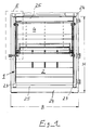
- FIG 1 shows the front view of an inventive Landing door 1, which is on the right side of the housing 24 of the baler is articulated to be vertical Rotation axis can be pivoted.
- the landing door 1 consists of special from a press shaft door 2 with a door frame from two vertical door frame profiles 23 and two horizontal door frame profiles 25.
- a filling shaft opening is provided, the one in Figure 1 in its closed position
- the feed shaft door shown is closed. After opening the hopper door 4 becomes the hopper opening released and the material to be destroyed can in the The baler shaft can be filled.
- the press shaft door 2 has the width B and the height H here on.
- the hopper door 4 is in each of them Positions, especially in the fully open position, essentially within this in the door plane of the Landing door 1 lying dimension B and also preferably still within the dimension H.
- Figure 2 shows the detail "E” from Figure 1.
- They are Door frame profiles 23 and 25, preferably 4-square tubes, the Press shaft door 2 can be seen.
- the in the Filled shaft door 4 is shown in the closed position.
- the landing door 1 is also mirror-symmetrical their vertical central axis, so that the detail "E” according to FIG. 2 in mirror-symmetrical form also in the right upper half of the landing door 1 is present in Detail but without the one shown in FIG. 7 and later proximity switch 37 described.
- Figure 3 shows the section A-A according to Figure 2. It is the Press shaft door 2 with the upper horizontal door frame tube 25 to recognize.
- the hopper door 4 closes the hopper opening 3.
- Guideway body 5,6 and 7, which on the vertical Door frame tube 23 are attached, as in Figure 2 can be seen.
- guideway bodies 5, 6 and 7 it can individual parts in the form of sufficiently thick sheets act, but they can also act as a single integral Be formed component in which the guideways 9 and 10 are incorporated.
- the guideway 9 is in the essentially formed by the guideway body 6. At least in its upper area, which extends from the door frame tube 25 runs obliquely below, the guide track 9 is on both sides limited, namely upwards by the guideway body 5 and down from the guideway body 6. Preferably, the Guide track 9 also in its vertical section limited on both sides, namely on the one hand by the Guideway body 6 and a guideway cover 26, at which can be a sheet which can be attached to the Guideway bodies 5.6 and 7 is attached.
- Guideway 10 in both upper substantially horizontal section as also in its vertical section on both sides limited, namely on the one hand by the lower area of the Guideway body 6 and the upper region of the Guideway body 7 and on the other hand by the Guideway cover 26 and the guideway body 7.
- the two carrier plates 27 each carry 2 tracking bodies in the form of two track wheels 8 and 11.
- the track wheels 8 and 11 are rotatably supported on the wheel axles 28 and 28 ', which of the Carrier plate 27 are worn.
- the movement of the top Track wheels 8 is guided by the guideway 9, while the Movement of the lower track wheel 11 from the guideway 10 to be led.
- Locking device by means of which Filler shaft door 4 in its closed position on the Press shaft door 2 can be locked.
- the Locking device has a toggle-like Locking lever 15, which is pivotable on a Actuating rod 19 is mounted.
- the operating rod 19 is at both ends of one of the carrier plates 27 held.
- One likewise held by the carrier plate 27 Stop screw 29 protrudes into a locking lever 15 provided slot 30, the center line of the Arc of a circle with a center that is with the longitudinal axis of the actuating rod 19 coincides.
- the Stop screw 29 thus determines the maximum possible Swivel angle by which the locking lever 15 to the Longitudinal axis of the actuating rod 19 can be pivoted.
- the hopper door 4 is first unlocked by the Connecting rod 18 to the front or in FIG. 3 is pulled to the left.
- the Locking lever 15 in a counterclockwise direction around the longitudinal axis the actuating rod 19 and the locking recess 16 there the locking pin 31 free.
- the connecting rod 18 is pulled further forward, so that the lower track wheel 11 in the horizontal section of the Guideway 10 forward or in Figure 3 after left rolls as shown in Figure 4.
- the upper track wheel 8 essentially not, but its wheel axle 28 serves as a fulcrum for the Swiveling movement of the feed shaft door 4 clockwise.
- the Filling shaft door 4 thus performs a pure rotational movement until they are in the position shown in Figure 4 located.
- the swivel angle of this movement is in the range between approximately 3 ° and 10 °.
- FIG. 5 The next movement section when opening the filling shaft door 4 is shown in FIG. 5.
- the connecting rod 18 is pulled further forward or left, so that the lower track wheel 11 runs through the curve between the horizontal section and the vertical section of the guideway 10 according to the arrow P 1 '.
- the upper track wheel 8 moves downward along the inclined section of the guide track 9 according to arrow Pi. If the upper track wheel 8 has finally reached beyond the end of the inclined section of the guideway 9 in the vertical section of the guideway 9, the filling shaft door 4 is in a position partially closing the filling shaft opening 3 according to FIG. 5.
- the loading shaft door 4 executes a translational movement which is overlaid by a rotational movement. It can be clearly seen in FIG. 5 that the loading shaft door 4 is displaced to the front or left when it is opened from the door plane of the pressing shaft door 2.
- Gap can be in the front area of the lower edge 34 Cover plate 35 can be provided, which is shown in FIG is shown. This prevents parts of the jam the material to be filled in the gap.
- Figure 7 also shows a dash-dotted line Edge profile 36 of the press housing on which a Proximity switch 37 is arranged.
- Proximity switch 37 can be an inductive one Proximity switch, a reed contact switch or the like Act switches, which when removing a switching flag 38th from the proximity switch 37 a signal to the Forward machine control according to which of the Press drive is shut down for safety reasons.
- Switch flag 38 can be a coded magnet, for example serve.
- An essential feature of the proximity switch 37 is that it has a tolerance zone in which the switching flag 38 can move without the Press drive is shut down.
- the switching flag 38 is on one Carrier rod 39, which as an extension of the wheel axis 28 of the lower track wheel 11 is formed.
- the switching flag 38 protrudes to the left beyond the door frame tube 23 and is located in the closed position of the hopper door 4 in the Tolerance zone of the proximity switch 37, if the Press shaft door 2 is closed.
- the size of the counterweights 20 corresponds approximately to the weight of the filler door 4. This makes the position infinitely adjustable the hopper door 4 enables. Because of the friction between the guideways 9 and 10 and Track wheels 8 and 11 and between the rope 21 and the rope pulley 22 is the filling shaft door 4, rope 21, Rope pulley 22 and counterweights 20 existing system self-locking. Another advantage of the rope suspension is in that the hopper door 4 in the in Figures 5 and 6 shown positions of the rope 21 always in the direction of Press shaft door 2 is pulled so that the Guideway cover 26 is essentially non-load bearing Must take over function.
- the Geometry and / or mass distribution of the locking lever 15 is advantageously chosen in such a way that be Focus always behind or in Figures 3 to 6 always to the right of its pivot axis, in the case of the one shown Embodiment behind or to the right of the longitudinal axis of the actuating rod 19 is located. Thereby it is ensured that the closure recess 16 when Closing the feed shaft door 4 via the locking pin 31 takes hold.
- the locking lever 15 of course also with spring elements in the locked position be biased.
- surface 41 ensures that the Locking lever 15 when closing the hopper door 4 from the locking pin 31 is rotated counterclockwise as far as until the locking recess 16 from above over the locking pin 31st can grab.
- FIGS. 9A and 9B show part of the press shaft door 2 shown together with the guideway bodies 5,6 and 7.
- the stops 12, 13, 14 and 32 are closed detect.
Landscapes
- Engineering & Computer Science (AREA)
- Mechanical Engineering (AREA)
- Power-Operated Mechanisms For Wings (AREA)
- Preliminary Treatment Of Fibers (AREA)
- Elevator Door Apparatuses (AREA)
- Operating, Guiding And Securing Of Roll- Type Closing Members (AREA)
- Press Drives And Press Lines (AREA)
Abstract
Description
Anstelle des Gegengewichts können entsprechend Notwendigkeit auch Zugfedern, Gasfedern, pneumatische oder dergleichen Mittel verwendet werden.
- Figur 1
- eine Aufsicht auf eine erfindungsgemäße Schachttür;
- Figur 2
- eine Ansicht der Einzelheit E gemäß Fig.1;
- Figur 3
- eine Schnittansicht gemäß Schnitt A-A in Fig.2, wobei sich die Einfüllschachttür in ihrer vollständig geschlossenen Stellung befindet;
- Figur 4
- eine Schnittansicht gemäß Schnitt A-A in Fig.2, wobei sich die Einfüllschachttür in ihrer nach vorne geschwenkten Stellung befindet;
- Figur 5
- eine Schnittansicht gemäß Schnitt A-A in Fig.2, wobei sich die Einfüllschachttür in einer noch teilweise geschlossenen, parallel zur Preßschachttür nach vorne versetzten Stellung befindet;
- Figur 6
- eine Schnittansicht gemäß Schnitt A-A in Fig.2, wobei sich die Einfüllschachttür in ihrer vollständig geöffneten Stellung befindet;
- Figur 7
- eine Schnittansicht gemäß Schnitt B-B in Fig.6, die um 90° gedreht wurde;
- Figur 8A
- eine Ansicht eines Teils der Einfüllschachttür;
- Figur 8B
- eine Seitenansicht der Einfüllschachttür gemäß Fig.8A;
- Figur 9A
- eine Ansicht eines Teils der Preßschachttür mit einer erfindungsgemäßen Führungsbahneinheit;
- Figur 9B
- eine Seitenansicht der Preßschachttür gemäß Fig.9A
- 1
- Schachttür
- 2
- Preßschachttür
- 3
- Einfüllschachtöffnung
- 4
- Einfüllschachttür
- 5
- Führungseinrichtung
- 6
- Führungseinrichtung
- 7
- Führungseinrichtung
- 8
- Spurfolgekörper
- 9
- Führungsbahn
- 10
- weitere Führungsbahn
- 11
- weiterer Spurfolgekörper
- 12
- Anschlag (geöffnet)
- 13
- Anschlag (geschlossen)
- 14
- Anschlag
- 15
- Verschlußhebel
- 16
- Verschlußaussparung
- 18
- Verbindungsstange
- 19
- Betätigungsstange
- 20
- Gegengewicht
- 21
- flexibles Verbindungsorgan
- 22
- Umlenkkörper
- 23
- Türrahmenrohr (vertikal)
- 24
- Gehäuse der Ballenpresse
- 25
- Türrahmenrohr (horizontal)
- 26
- Führungsbahnabdeckung
- 27
- Trägerplatte
- 28, 28'
- Radachsen
- 29
- Anschlagschraube
- 30
- Langloch
- 31
- Rastbolzen
- 32
- Anschlag
- 33
- Oberkante (Einfüllschachttür)
- 34
- Unterkante (Einfüllschachtöffnung)
- 35
- Abdeckblech
- 36
- Kantprofil
- 37
- Annäherungsschalter
- 38
- Schaltfahne
- 39
- Trägerstange
- 40
- Seilbefestigungsscheibe
- 41
- Auflauffläche
- 42
- Abstandsleisten
- A-A
- Schnitt entlang der Linie 'A-A'
- B-B
- Schnitt entlang der Linie 'B-B'
- B
- Breite ( von Pos. 2 und/oder Pos. 24)
- H
- Höhe ( von pos. 2 und/oder Pos. 24)
- P1, P1'
- Pfeilrichtung (Bewegungsrichtung)
Claims (17)
- Schachttür für eine Ballenpresse, bestehend ausdadurch gekennzeichnet,einer Preßschachttür (2) mit einer Einfüllschachtöffnung (3) undeiner Einfüllschachttür (4), mittels welcher die Einfüllschachtöffnung (3) verschließbar ist,
daß die Einfüllschachttür (4) am Gehäuse (24) der Ballenpresse oder an der Preßschachttür (2), zwischen einer oberen Position und einer unteren Position, im wesentlichen vertikal bewegbar sowie arretierbar angeordnet ist und, daß die Einfüllschachttür (4) in ihrer oberen Position die Einfüllschachtöffnung (3) verschließt und in ihrer unteren Position selbige (3) vollständig freigibt. - Schachttür für eine Ballenpresse, bestehend ausdadurch gekennzeichnet,einer Preßschachttür (2) mit einer Einfüllschachtöffnung (3) undeiner Einfüllschachttür (4), mittels welcher die Einfüllschachtöffnung (3) verschließbar ist,
daß zumindest an der Preßschachttür (2) eine Führungseinrichtung (5,6,7) vorgesehen ist, mit deren Hilfe die Einfüllschachttür (4) im wesentlichen parallel zur Türebene der Preßschachttür (2) zwischen einer geschlossenen Stellung und einer geöffneten Stellung verschiebbar ist, wobei die Einfüllschachttür (4) in der geöffneten Stellung im Wesentlichen innerhalb der seitlichen Außenabmessungen der Preßschachttür (2) zu liegen kommt. - Schachttür unter Anspruch 1 oder 2, dadurch gekennzeichnet,
daß die in der unteren Position befindliche Einfüllschachttür (4) und die Preßschachttür (2) mit ihren jeweiligen Oberkanten gemeinsam einen Arbeitstisch bilden, dessen Tiefe im Wesentlichen der Summe der Dicken der beiden Türen (2 und 4) entspricht. - Schachttür unter Anspruch 2,
dadurch gekennzeichnet,
daß die Führungseinrichtung aus zwei Führungsbahneinheiten (5,6,7) besteht, welche jeweils vertikal verlaufend an den Außenbereichen der Preßschachttür (2) angeordnet sind, und die Einfüllschachttür (4) an jeder ihrer vertikal verlaufenden Stirnseiten jeweils wenigstens einen Spurfolgekörper (8) aufweist, der von einer Führungsbahn (9) der jeweiligen Führungsbahneinheit (5,6,7) geführt wird. - Schachttür unter Anspruch 4,
dadurch gekennzeichnet,
daß jede Führungseinheit aus drei im wesentlichen untereinander angeordneten Führungsbahnkörpern (5,6,7) besteht, welche die Führungsbahn (9) und eine weitere Führungsbahn (10) definieren, und an jeder Stirnseite der Einfüllschachttür (4) ein weiterer Spurfolgekörper (11) vorgesehen ist, der von der weiteren Führungsbahn (10) geführt wird. - Schachttür unter Anspruch 5,
dadurch gekennzeichnet,
daß der unterste Führungskörper (7) in seinem unteren Bereich einen Anschlag (12) aufweist, der die Einfüllschachttür (4) in der geöffneten Stellung hält. - Schachttür unter Anspruch 5 oder 6,
dadurch gekennzeichnet,
daß der unterste Führungskörper (7) in seinem oberen Bereich einen Anschlag (13) aufweist, der die Einfüllschachttür (4) in der geschlossenen Stellung hält. - Schachttür unter einem der Ansprüche 4 bis 7,
dadurch gekennzeichnet,
daß die Führungsbahn (9) auf einen Bereich der Preßschachttür (2) zuläuft, der einen Anschlag (14) bildet, an welchem der Spurfolgekörper (8) in der geschlossenen Stellung anliegt und welcher im wesentlichen den Drehpunkt der zu Beginn des Öffnens der Einfüllschachttür (4) auftretenden Schwenkbewegung darstellt. - Schachttür unter einem der vorangehenden Ansprüchen,
dadurch gekennzeichnet,
daß die Einfüllschachttür (4) eine Verriegelungseinrichtung aufweist, mittels welcher sie an der Preßschachttür (2) verriegelbar ist. - Schachttür unter Anspruch 9,
dadurch gekennzeichnet,
daß die Verriegelungseinrichtung aus zwei an der Einfüllschachttür (4) angelenkten Verschlußhebeln (15) mit jeweils einer Verschlußaussparung (16) besteht, wobei der jeweilige Verschlußhebel (15) durch Verschwenken in eine verriegelte Stellung gebracht werden kann, in welcher die jeweilige Verschlußaussparung (16) jeweils einen an der Preßschachttür (2) befestigten Rastbolzen (31) wenigstens teilweise vorgreift. - Schachttür unter Anspruch 10,
dadurch gekennzeichnet,
daß die beiden Verschlußhebel (15) mittels einer Verbindungsstange (18) miteinander verbunden sind, so daß sie gleichzeitig betätigt werden können. - Schachttür unter einem der vorangehenden Ansprüchen,
dadurch gekennzeichnet,
daß im unteren Bereich der Einfüllschachttür (4) eine Betätigungsstange (19) zum Anheben der Einfüllschachttür (4) von der geöffneten Stellung in die geschlossene Stellung angeordnet ist. - Schachttür unter Anspruch 12 im Vergleich mit Anspruch 10 oder 11,
dadurch gekennzeichnet,
daß die Verschlußhebel (15) auf der Betätigungsstange (19) gelagert sind, so daß deren Längsachse den Drehpunkt des Verschlußhebels (15) bildet. - Schachttür unter einem der vorangehenden Ansprüchen,
dadurch gekennzeichnet,
daß wenigstens eine gewichtsausgleichende Mechanik an der Preßschachttür (2) vorgesehen ist, die mit der Einfüllschachttür (4) verbunden ist und mit letzterer (4) in Wirkverbindung steht. - Schachttür unter Anspruch 14,
dadurch gekennzeichnet,
daß die gewichtsausgleichende Mechanik wenigstens ein Gegengewicht (20) ist, welches mittels eines flexiblen Verbindungsorgans (21), das über einen Umlenkkörper (22) geführt ist, mit der Einfüllschachttür (4) verbunden ist. - Schachttür unter Anspruch 15,
dadurch gekennzeichnet,
daß das Gegengewicht (20) in einem vertikal verlaufenden, hohlen Türrahmenprofil (23) der Preßschachttür (2) vertikal verschieblich an dem Verbindungsorgan (21) hängt. - Ballenpresse zum Herstellen verdichteter Abfallballen, bestehend aus einem den Preßschacht begrenzenden Pressengehäuse mit Schachtöffnung und einer die Schachtöffnung verschließenden Schachttür (1),
dadurch gekennzeichnet,
daß die Schachttür (1) nach einem der vorangehenden Ansprüche ausgebildet ist.
Priority Applications (4)
| Application Number | Priority Date | Filing Date | Title |
|---|---|---|---|
| ES99108132T ES2277400T3 (es) | 1999-04-26 | 1999-04-26 | Puerta de caja para un prensabalas de tipo vertical. |
| AT99108132T ATE346743T1 (de) | 1999-04-26 | 1999-04-26 | Schachttür für eine ballenpresse vertikaler bauart |
| EP99108132A EP1048449B1 (de) | 1999-04-26 | 1999-04-26 | Schachttür für eine Ballenpresse vertikaler Bauart |
| DK99108132T DK1048449T3 (da) | 1999-04-26 | 1999-04-26 | Skaktdör til en ballepresse af vertikal konstruktion |
Applications Claiming Priority (1)
| Application Number | Priority Date | Filing Date | Title |
|---|---|---|---|
| EP99108132A EP1048449B1 (de) | 1999-04-26 | 1999-04-26 | Schachttür für eine Ballenpresse vertikaler Bauart |
Publications (2)
| Publication Number | Publication Date |
|---|---|
| EP1048449A1 true EP1048449A1 (de) | 2000-11-02 |
| EP1048449B1 EP1048449B1 (de) | 2006-11-29 |
Family
ID=8238042
Family Applications (1)
| Application Number | Title | Priority Date | Filing Date |
|---|---|---|---|
| EP99108132A Expired - Lifetime EP1048449B1 (de) | 1999-04-26 | 1999-04-26 | Schachttür für eine Ballenpresse vertikaler Bauart |
Country Status (4)
| Country | Link |
|---|---|
| EP (1) | EP1048449B1 (de) |
| AT (1) | ATE346743T1 (de) |
| DK (1) | DK1048449T3 (de) |
| ES (1) | ES2277400T3 (de) |
Cited By (1)
| Publication number | Priority date | Publication date | Assignee | Title |
|---|---|---|---|---|
| EP2428354A1 (de) * | 2010-09-09 | 2012-03-14 | Bramidan A/S | Automatische Tür für eine Ballenpresse |
Citations (9)
| Publication number | Priority date | Publication date | Assignee | Title |
|---|---|---|---|---|
| DE1627934A1 (de) * | 1968-02-20 | 1971-07-29 | Lindemann Maschfab Gmbh | Ballenpresse fuer faseriges Gut |
| US3824920A (en) * | 1973-01-02 | 1974-07-23 | Gladwin Floyd Ralph | Compactor cabinet shield |
| US3937140A (en) * | 1974-10-03 | 1976-02-10 | Muncher Corporation | Baler with exterior platen guide |
| US5044271A (en) * | 1990-03-29 | 1991-09-03 | Marathon Equipment Company | Compactor door and interlock |
| DE9401138U1 (de) * | 1994-01-25 | 1994-03-31 | Jumbo Pressen GmbH, 88374 Hoßkirch | Ballenpresse |
| US5517908A (en) * | 1994-07-25 | 1996-05-21 | Stout; Robert P. | Baler for compacting and then loading hazardous waste into cartons |
| DE19545766A1 (de) * | 1994-12-27 | 1996-07-04 | Hermann Schwelling | Sicherheitsfronttür für Ballenpressen |
| DE29721746U1 (de) * | 1997-12-09 | 1998-02-12 | Schwelling, Hermann, 88682 Salem | Einfüllklappen-Verschlußvorrichtung für Abfall-Ballenpressen |
| EP0865901A2 (de) * | 1997-03-11 | 1998-09-23 | Strautmann Umwelttechnik und Recycling Gesellschaft mbH & Co. KG | Ballenpresse |
-
1999
- 1999-04-26 DK DK99108132T patent/DK1048449T3/da active
- 1999-04-26 AT AT99108132T patent/ATE346743T1/de active
- 1999-04-26 EP EP99108132A patent/EP1048449B1/de not_active Expired - Lifetime
- 1999-04-26 ES ES99108132T patent/ES2277400T3/es not_active Expired - Lifetime
Patent Citations (9)
| Publication number | Priority date | Publication date | Assignee | Title |
|---|---|---|---|---|
| DE1627934A1 (de) * | 1968-02-20 | 1971-07-29 | Lindemann Maschfab Gmbh | Ballenpresse fuer faseriges Gut |
| US3824920A (en) * | 1973-01-02 | 1974-07-23 | Gladwin Floyd Ralph | Compactor cabinet shield |
| US3937140A (en) * | 1974-10-03 | 1976-02-10 | Muncher Corporation | Baler with exterior platen guide |
| US5044271A (en) * | 1990-03-29 | 1991-09-03 | Marathon Equipment Company | Compactor door and interlock |
| DE9401138U1 (de) * | 1994-01-25 | 1994-03-31 | Jumbo Pressen GmbH, 88374 Hoßkirch | Ballenpresse |
| US5517908A (en) * | 1994-07-25 | 1996-05-21 | Stout; Robert P. | Baler for compacting and then loading hazardous waste into cartons |
| DE19545766A1 (de) * | 1994-12-27 | 1996-07-04 | Hermann Schwelling | Sicherheitsfronttür für Ballenpressen |
| EP0865901A2 (de) * | 1997-03-11 | 1998-09-23 | Strautmann Umwelttechnik und Recycling Gesellschaft mbH & Co. KG | Ballenpresse |
| DE29721746U1 (de) * | 1997-12-09 | 1998-02-12 | Schwelling, Hermann, 88682 Salem | Einfüllklappen-Verschlußvorrichtung für Abfall-Ballenpressen |
Cited By (3)
| Publication number | Priority date | Publication date | Assignee | Title |
|---|---|---|---|---|
| EP2428354A1 (de) * | 2010-09-09 | 2012-03-14 | Bramidan A/S | Automatische Tür für eine Ballenpresse |
| WO2012032115A2 (en) | 2010-09-09 | 2012-03-15 | Bramidan A/S | An automatic door for a baler |
| WO2012032115A3 (en) * | 2010-09-09 | 2012-06-07 | Bramidan A/S | An automatic door for a baler |
Also Published As
| Publication number | Publication date |
|---|---|
| ES2277400T3 (es) | 2007-07-01 |
| ATE346743T1 (de) | 2006-12-15 |
| EP1048449B1 (de) | 2006-11-29 |
| DK1048449T3 (da) | 2007-03-05 |
Similar Documents
| Publication | Publication Date | Title |
|---|---|---|
| EP2539528B1 (de) | Hubtor mit einer beweglichen torblattführung | |
| EP0042580B1 (de) | Vorrichtung zum Verdichten von Müll in offenen Containern | |
| EP2737152B1 (de) | Hubtor mit einer beweglichen torblattführung | |
| AT4784U1 (de) | Sektionalhub- oder falttor | |
| EP0472870B1 (de) | Pressvorrichtung für Abfälle, insbesondere für Müll | |
| EP3747643A2 (de) | Pressgutzufördervorrichtung für eine vertikale ballenpresse und ballenpresse mit pressgutzufördervorrichtung | |
| DE19817807B4 (de) | Schachttür für eine Ballenpresse und zugehörige Ballenpresse | |
| DE2926113C2 (de) | Verriegelungsvorrichtung für Hebe-Schiebe-Kipp-Türen oder -Fenster | |
| DE2261385C3 (de) | Elektromagnetische Verriegelungsvorrichtung eines Schlosses | |
| DE10309030B3 (de) | Kniehebelpresse | |
| EP1681419A1 (de) | Vertikal-Steuervorrichtung für einen Hebe-Schiebeflügel | |
| DE2929782C2 (de) | Vorrichtung zum Ausschneiden und Transportieren eines Gärfutterblockes | |
| EP1048449B1 (de) | Schachttür für eine Ballenpresse vertikaler Bauart | |
| CH657570A5 (de) | Einwurftuer an einer ballenpresse. | |
| DE3023508C1 (de) | Vorrichtung zum Verdichten von aus Verpackungsmaterial und leicht preßbaren Abfällen bestehendem Müll | |
| EP3453529B1 (de) | Kasten-ballenpresse mit schiebetür sowie verfahren zum betreiben einer solchen kastenpresse | |
| EP0139046B1 (de) | Schiebetür- oder Schiebefensteranordnung | |
| DE2521570B2 (de) | Paketierpresse | |
| DE9004989U1 (de) | Ballenpresse | |
| DE3133028C2 (de) | Vorrichtung zur vereinzelten Entnahme blattförmiger Druckereierzeugnisse, insbesondere Zeitungen | |
| DE19912059A1 (de) | Verfahren zum Verdichten von Leergut sowie Preßvorrichtung für Leergut | |
| DE9412658U1 (de) | Vorrichtung zum Spalten von Holzstücken in einem Behälter | |
| DE2903531C2 (de) | ||
| DE2225620C3 (de) | Flachstapel-Bogenanleger, dessen Trennsaugschloß über eine verstellbare Welle steuerbar ist | |
| DE2145704A1 (de) | Stehende Ballenpresse |
Legal Events
| Date | Code | Title | Description |
|---|---|---|---|
| PUAI | Public reference made under article 153(3) epc to a published international application that has entered the european phase |
Free format text: ORIGINAL CODE: 0009012 |
|
| AK | Designated contracting states |
Kind code of ref document: A1 Designated state(s): AT DK ES FR GB SE |
|
| AX | Request for extension of the european patent |
Free format text: AL;LT;LV;MK;RO;SI |
|
| 17P | Request for examination filed |
Effective date: 20010502 |
|
| AKX | Designation fees paid |
Free format text: AT DK ES FR GB SE |
|
| 17Q | First examination report despatched |
Effective date: 20040823 |
|
| REG | Reference to a national code |
Ref country code: DE Ref legal event code: 8566 |
|
| GRAP | Despatch of communication of intention to grant a patent |
Free format text: ORIGINAL CODE: EPIDOSNIGR1 |
|
| GRAS | Grant fee paid |
Free format text: ORIGINAL CODE: EPIDOSNIGR3 |
|
| GRAA | (expected) grant |
Free format text: ORIGINAL CODE: 0009210 |
|
| AK | Designated contracting states |
Kind code of ref document: B1 Designated state(s): AT DK ES FR GB SE |
|
| REG | Reference to a national code |
Ref country code: GB Ref legal event code: FG4D Free format text: NOT ENGLISH |
|
| GBT | Gb: translation of ep patent filed (gb section 77(6)(a)/1977) |
Effective date: 20070117 |
|
| REG | Reference to a national code |
Ref country code: DK Ref legal event code: T3 |
|
| REG | Reference to a national code |
Ref country code: SE Ref legal event code: TRGR |
|
| ET | Fr: translation filed | ||
| REG | Reference to a national code |
Ref country code: ES Ref legal event code: FG2A Ref document number: 2277400 Country of ref document: ES Kind code of ref document: T3 |
|
| PLBE | No opposition filed within time limit |
Free format text: ORIGINAL CODE: 0009261 |
|
| STAA | Information on the status of an ep patent application or granted ep patent |
Free format text: STATUS: NO OPPOSITION FILED WITHIN TIME LIMIT |
|
| 26N | No opposition filed |
Effective date: 20070830 |
|
| PGFP | Annual fee paid to national office [announced via postgrant information from national office to epo] |
Ref country code: GB Payment date: 20140530 Year of fee payment: 16 |
|
| PGFP | Annual fee paid to national office [announced via postgrant information from national office to epo] |
Ref country code: FR Payment date: 20140415 Year of fee payment: 16 Ref country code: AT Payment date: 20140414 Year of fee payment: 16 |
|
| PGFP | Annual fee paid to national office [announced via postgrant information from national office to epo] |
Ref country code: ES Payment date: 20150331 Year of fee payment: 17 |
|
| REG | Reference to a national code |
Ref country code: AT Ref legal event code: MM01 Ref document number: 346743 Country of ref document: AT Kind code of ref document: T Effective date: 20150426 |
|
| GBPC | Gb: european patent ceased through non-payment of renewal fee |
Effective date: 20150426 |
|
| PG25 | Lapsed in a contracting state [announced via postgrant information from national office to epo] |
Ref country code: GB Free format text: LAPSE BECAUSE OF NON-PAYMENT OF DUE FEES Effective date: 20150426 |
|
| REG | Reference to a national code |
Ref country code: FR Ref legal event code: ST Effective date: 20151231 |
|
| PG25 | Lapsed in a contracting state [announced via postgrant information from national office to epo] |
Ref country code: FR Free format text: LAPSE BECAUSE OF NON-PAYMENT OF DUE FEES Effective date: 20150430 Ref country code: AT Free format text: LAPSE BECAUSE OF NON-PAYMENT OF DUE FEES Effective date: 20150426 |
|
| PG25 | Lapsed in a contracting state [announced via postgrant information from national office to epo] |
Ref country code: ES Free format text: LAPSE BECAUSE OF NON-PAYMENT OF DUE FEES Effective date: 20160427 |
|
| REG | Reference to a national code |
Ref country code: ES Ref legal event code: FD2A Effective date: 20180626 |
|
| PGFP | Annual fee paid to national office [announced via postgrant information from national office to epo] |
Ref country code: DK Payment date: 20180424 Year of fee payment: 20 |
|
| PGFP | Annual fee paid to national office [announced via postgrant information from national office to epo] |
Ref country code: SE Payment date: 20180424 Year of fee payment: 20 |
|
| REG | Reference to a national code |
Ref country code: DK Ref legal event code: EUP Effective date: 20190426 |
|
| REG | Reference to a national code |
Ref country code: SE Ref legal event code: EUG |