EP1048844A1 - Verfahren und Vorrichtung zum Starten, Bremsen und Umsteuern eines Zweitakt-dieselmotors - Google Patents
Verfahren und Vorrichtung zum Starten, Bremsen und Umsteuern eines Zweitakt-dieselmotors Download PDFInfo
- Publication number
- EP1048844A1 EP1048844A1 EP00810307A EP00810307A EP1048844A1 EP 1048844 A1 EP1048844 A1 EP 1048844A1 EP 00810307 A EP00810307 A EP 00810307A EP 00810307 A EP00810307 A EP 00810307A EP 1048844 A1 EP1048844 A1 EP 1048844A1
- Authority
- EP
- European Patent Office
- Prior art keywords
- cylinder
- dead center
- diesel engine
- degrees
- otp
- Prior art date
- Legal status (The legal status is an assumption and is not a legal conclusion. Google has not performed a legal analysis and makes no representation as to the accuracy of the status listed.)
- Granted
Links
Images


Classifications
-
- F—MECHANICAL ENGINEERING; LIGHTING; HEATING; WEAPONS; BLASTING
- F02—COMBUSTION ENGINES; HOT-GAS OR COMBUSTION-PRODUCT ENGINE PLANTS
- F02B—INTERNAL-COMBUSTION PISTON ENGINES; COMBUSTION ENGINES IN GENERAL
- F02B25/00—Engines characterised by using fresh charge for scavenging cylinders
-
- F—MECHANICAL ENGINEERING; LIGHTING; HEATING; WEAPONS; BLASTING
- F02—COMBUSTION ENGINES; HOT-GAS OR COMBUSTION-PRODUCT ENGINE PLANTS
- F02N—STARTING OF COMBUSTION ENGINES; STARTING AIDS FOR SUCH ENGINES, NOT OTHERWISE PROVIDED FOR
- F02N9/00—Starting of engines by supplying auxiliary pressure fluid to their working chambers
- F02N9/04—Starting of engines by supplying auxiliary pressure fluid to their working chambers the pressure fluid being generated otherwise, e.g. by compressing air
-
- F—MECHANICAL ENGINEERING; LIGHTING; HEATING; WEAPONS; BLASTING
- F02—COMBUSTION ENGINES; HOT-GAS OR COMBUSTION-PRODUCT ENGINE PLANTS
- F02B—INTERNAL-COMBUSTION PISTON ENGINES; COMBUSTION ENGINES IN GENERAL
- F02B75/00—Other engines
- F02B75/02—Engines characterised by their cycles, e.g. six-stroke
- F02B2075/022—Engines characterised by their cycles, e.g. six-stroke having less than six strokes per cycle
- F02B2075/025—Engines characterised by their cycles, e.g. six-stroke having less than six strokes per cycle two
-
- F—MECHANICAL ENGINEERING; LIGHTING; HEATING; WEAPONS; BLASTING
- F02—COMBUSTION ENGINES; HOT-GAS OR COMBUSTION-PRODUCT ENGINE PLANTS
- F02B—INTERNAL-COMBUSTION PISTON ENGINES; COMBUSTION ENGINES IN GENERAL
- F02B3/00—Engines characterised by air compression and subsequent fuel addition
- F02B3/06—Engines characterised by air compression and subsequent fuel addition with compression ignition
-
- F—MECHANICAL ENGINEERING; LIGHTING; HEATING; WEAPONS; BLASTING
- F02—COMBUSTION ENGINES; HOT-GAS OR COMBUSTION-PRODUCT ENGINE PLANTS
- F02F—CYLINDERS, PISTONS OR CASINGS, FOR COMBUSTION ENGINES; ARRANGEMENTS OF SEALINGS IN COMBUSTION ENGINES
- F02F7/00—Casings, e.g. crankcases
- F02F2007/0097—Casings, e.g. crankcases for large diesel engines
Definitions
- the invention relates to a method for starting, braking and reversing a two-stroke diesel engine according to the preamble of claim 1. Die The invention further relates to an apparatus for performing the method according to the preamble of claim 11.
- Diesel engines it is known auto-ignition reciprocating internal combustion engines, in the rest also referred to as diesel engines to start pneumatically, to brake or to change direction.
- large ones are used to drive Ships used two-stroke diesel engines started in such a way that first operating phase a compressed fluid, in particular compressed air, such is blown into the cylinder so that the pistons located in it Movement are set and drive the diesel engine, after the Reaching a minimum speed of the cylinders in a second Operating phase fuel is supplied and the cylinders in the sense of a continuing internal combustion engine operation are ignited.
- Diesel engines can be used like the compressed fluid Also brake the compressed air, if necessary to a standstill. If if necessary, the diesel engine can also be reversed by the rotating diesel engine is brought to a standstill and in the opposite direction is started again.
- compressed fluid is particularly suitable for compressed air, but other, non-flammable fluids can be used.
- Compressed air stores of this type are very large, bulky and expensive, and expensive compressors are also required for reloading.
- the object of the present invention is an economically more advantageous one Method and a corresponding device for starting, braking and Propose reversing a two-stroke diesel engine.
- the task is solved in particular with a method for starting, Braking or reversing a two-stroke diesel engine by one compressed fluid, in particular compressed air, such as at least one cylinder is supplied that a piston located in the cylinder through the resulting pressure change in motion or is braked, the cylinder having at least one exhaust valve, which opens variably with respect to the angle of rotation of the crankshaft and is closed to the cylinder essentially without compression hold, or to cause a premature pressure drop in the cylinder, and wherein the delivery of the compressed fluid and the discharge from the Cylinders mutually dependent on the angle of rotation of the crankshaft is coordinated that through the interaction an increased Pressure change in the cylinder is generated.
- one compressed fluid in particular compressed air, such as at least one cylinder is supplied that a piston located in the cylinder through the resulting pressure change in motion or is braked
- the cylinder having at least one exhaust valve, which opens variably with respect to the angle of rotation of the crankshaft and is closed to the cylinder essentially without compression hold, or to cause a premature
- the requirement for performing the procedure is that the diesel engine Has valves which are mechanically separated from the crankshaft are controllable.
- the valves become like this when the diesel engine is started controlled or kept open that the diesel engine in the can be started essentially without compression.
- a two-stroke diesel engine is started, for example, in such a way that one Cylinder whose piston is immediately after top dead center the outlet valve is closed and compressed air is blown in around the To move the piston towards bottom dead center.
- the exhaust valves of the the remaining cylinders remain open so that they are not essential Compression is generated.
- the exhaust valve is opened again so that the Pistons essentially return to top dead center without compression moved there.
- two cylinders can be used as described Compressed air can be applied to start the diesel engine during the other cylinders are kept essentially compression-free. It However, all cylinders can also be operated with compressed air as described be charged. Because the cylinder at the time the piston located at top dead center, is essentially compression-free prove to be an essential advantage of the method according to the invention The fact that a relatively low air pressure is enough to close the diesel engine start.
- the air used for starting had to be pressurized which was significantly higher than the compression pressure, which rests in the cylinder when starting, when the piston is in the upper one Dead center is located.
- the method according to the invention thus has the advantage that the pressure in the compressed air reservoir can be kept lower, or that the volume of the compressed air reservoir can be kept smaller.
- the Compressed air reservoir advantageously designed with pressure bottles, can thus be made cheaper or smaller, or it can be done with the Content of existing compressed air storage an increased number of starts carry out. In addition, cheaper compressors are available for charging the Compressed air storage can be used.
- the method according to the invention is also suitable for the diesel engine to change, in a first step like this is decelerated to a standstill, being in a second Partial step the compressed air depending on the piston position blown and the exhaust valves are controlled so that the Diesel engine is rotated in the opposite direction, so that in a third Partial step of the diesel engine rotating in the opposite direction with the one already described procedure is started.
- the method according to the invention is suitable for two-stroke diesel engines.
- the compressed air is from the compressed air tank 11 via the line 11b Compressed air valve 4b supplied.
- the exhaust valve 4a is an exhaust pipe 13 subordinate.
- the combustion air is above the cylinder in the two-stroke diesel engine located inlet slots not visible in the illustration.
- Fig. 2a shows the pressure 20 within a cylinder of the two-stroke diesel engine in function of the crank angle ⁇ of the crankshaft 2.
- the piston moves to bottom dead center UTP the cylinder pressure 20 decreases and first, as with curve 22 shown, the outlet valve 4a opens, and then, as with the curve 21 shown, the inlet slot of the two-stroke diesel engine is open.
- the inlet slot is closed first, then the Exhaust valve 4a closed, up the cylinder pressure 20 through the compression increases.
- FIG. 2b shows the cylinder pressure 20 as a function of the crank angle ⁇ at starting method according to the invention.
- the exhaust valve 4a is during the Curve 22 opened, curve 22 opening exhaust valve 4a Flank 22a and a flank 22b closing the outlet valve 4a having.
- the exhaust valve 4a In the normal operating state, i.e. during the operation of the Two-stroke diesel engine with constant speed, the exhaust valve 4a in essentially corresponding to the curve 22 shown in FIG. 2a opened and closed.
- the device according to the invention has the Property on that the exhaust valve 4a, as by the flanks 22a, 22b shown, opened and closed at freely selectable crank angles ⁇ can be.
- the inlet slot is in the courses according to Fig.
- the area 24a shows the pressure increase in the cylinder, based on which of the pistons one expanding movement.
- the outlet valve 4a is over the Control curve 22 and the compressed air valve 4b via the control curve 23 controlled so mutually coordinated that the cylinder at about top dead center OTP is essentially compression-free or one has low internal pressure, and that the subsequent injection of Compressed air an increased pressure change in the cylinder or one causes relatively high pressure change in the cylinder.
- the known method according to FIG. 2a is in the method according to FIG. 2b Compressed air with a much lower pressure is required, this Compressed air also causes an increased pressure change in the cylinder, which assists in expanding the piston. Otherwise the start goes like in the description of Fig. 2a already described by after Exceeding a specifiable nominal speed of the diesel engine in the Operating state of an internal combustion engine is transferred.
- the exhaust valve 4a is in a range between -180 degrees and 0 degrees before top dead center OTP, especially in a range between -90 Degrees and 0 degrees before top dead center OTP closed.
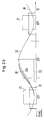
- Fig. 2c explains the cylinder pressure 20 as a function of the crank angle represents ⁇ .
- the compression stroke becomes the cylinder, as shown by curve 23, Compressed air supplied so that the pressure is above the pressure otherwise present 20a rises to the cylinder pressure 20, resulting in an area 24a increased cylinder pressure results.
- the exhaust valve as from curve 22, in particular can be seen from the opening flank 22a, prematurely or with respect to the Normal operation advanced to top dead center OTP, opened, whereupon the cylinder pressure 20 one compared to the otherwise existing Pressure 20b has significantly lower pressure, the difference of which by Surface 24b is shown.
- At least one of the cylinders is according to the invention Braking process controlled, whereby to a quick braking or a cause the diesel engine to come to a standstill, preferably all cylinders be controlled in this way.
- the exhaust valve is in a range between 0 degrees and 90 degrees after top dead center OTP, for example at about 45 degrees opened, namely when the opening force of the valve 4a Closing force caused by the pressure in the cylinder overcomes.
- the outlet valve 4a is via the control curve 22 and the compressed air valve 4b controlled in a mutually coordinated manner via the control curve 23, that the interior of the cylinder one during compression has increased internal pressure, and premature during expansion Pressure reduction shows what an increased pressure reduction in the interior of the cylinder, and less pressure energy for the Piston movement is available.
- FIG. 2d shows the cylinder pressure 20 as a function of the crank angle ⁇ at Reversing the diesel engine 1.
- the cylinder whose Piston is before top dead center OTP, as through curve 23 shown, compressed air supplied, which causes a pressure curve 20, which increased compared to the pressure curve 20a without the use of compressed air is.
- This causes the piston to rotate the crankshaft 2 in opposite directions Direction rotates so that the diesel engine 1 is reversed.
- the diesel engine 1 accelerated in accordance with the starting method shown in FIG. 2b be to the diesel engine in the Transfer internal combustion engine operation.
- reversing according to Fig. 2d could the interior of the cylinder by operating the exhaust valve 4a are initially made without compression, and after the Closing the exhaust valve 4a, the compressed air is supplied.
- the reversal of a running diesel engine is done in several Sub-steps in that in a first step the motor with the in Fig. 2c braking method shown is braked to a standstill, then in a second step with the reversal method shown in Fig. 2d whose direction of rotation is changed in a third step with the in Fig. 2b shown starting process the diesel engine in reverse Accelerate direction again and when crossing one Minimum fuel supply and the engine after igniting the To continue operating fuel in internal combustion engine operation.
- the method according to the invention has the advantage that the reversal can be done faster, so the diesel engine with fewer revolutions braked, reversed and driven in the opposite direction, and in the case of a ship propulsion, the ship within a shorter distance can be stopped.
Landscapes
- Engineering & Computer Science (AREA)
- Chemical & Material Sciences (AREA)
- Combustion & Propulsion (AREA)
- Mechanical Engineering (AREA)
- General Engineering & Computer Science (AREA)
- Output Control And Ontrol Of Special Type Engine (AREA)
- Valve Device For Special Equipments (AREA)
- Combined Controls Of Internal Combustion Engines (AREA)
Abstract
Description
- Fig. 1
- schematisch einen Zweitakt-Dieselmotor aufweisend eine Vorrichtung zur Durchführung des Verfahrens;
- Fig. 2a
- ein Diagramm darstellend den Zylinderdruck in Funktion des Kurbelwinkels beim Starten eines bekannten Zweitakt-Dieselmotors;
- Fig. 2b
- ein Diagramm darstellend den Zylinderdruck in Funktion des Kurbelwinkels beim Starten eines Zweitakt-Dieselmotors nach dem erfindungsgemässen Verfahren;
- Fig. 2c
- ein Diagramm darstellend den Zylinderdruck in Funktion des Kurbelwinkels beim Bremsen eines Zweitakt-Dieselmotors nach dem erfindungsgemässen Verfahren;
- Fig. 2d
- ein Diagramm darstellend den Zylinderdruck in Funktion des Kurbelwinkels beim Umsteuern eines Zweitakt-Dieselmotors nach dem erfindungsgemässen Verfahren.
- mit einem Drehwinkelsensor 9 verbunden, welcher den Drehwinkel der Kurbelwelle 2 erfasst;
- mit einem Auslassventil 4a verbunden,
- mit einem Druckluftventil 4b verbunden,
- mit der Einspritzpumpe 3 verbunden,
- sowie mit einem Sensor 12 zum Messen des Druckes im Druckluftbehälter 11 verbunden.
Claims (12)
- Verfahren zum Starten, Bremsen oder Umsteuern eines Zweitakt-Dieselmotors indem ein komprimiertes Fluid, insbesondere Druckluft, derart in Abhängigkeit vom Drehwinkel der Kurbelwelle zumindest einem Zylinder zugeführt wird, dass ein sich im Zylinder befindlicher Kolben durch die daraus resultierende Druckveränderung beschleunigt oder abgebremst wird, dadurch gekennzeichnet, dass das Auslassventil (4a) des Zylinders bezüglich dem Drehwinkel der Kurbelwelle variierbar geöffnet und geschlossen wird, wobei zum Starten die schliessende Flanke (22b) für das Auslassventil (4a) zum oberen Totpunkt (OTP) hin verschoben wird, sodass der Zylinder im wesentlichen kompressionslos gehalten wird, und wobei zum Bremsen die öffnende Flanke (22b) für das Auslassventil (4a) zum oberen Totpunkt (OTP) hin verschoben wird, sodass ein vorzeitiger Druckabfall im Zylinder resultiert.
- Verfahren nach Anspruch 1, dadurch gekennzeichnet, dass zum Starten die Auslassventile aller Zylinder geöffnet werden, dass das Auslassventil desjenigen Zylinder, dessen Kolben sich unmittelbar nach einem oberen Totpunkt (OTP) befindet, geschlossen wird, dass in diesen Zylinder das komprimierte Fluid zugeführt wird wodurch der Kolben zum unteren Totpunkt (UTP) hin bewegt wird, dass das Auslassventil geöffnet wird und spätestens nachdem sich der Kolben beim oberen Totpunkt (OTP) befindet wieder geschlossen wird, dass dem Zylinder, sobald sich der Kolben nach dem oberen Totpunkt (OTP) befindet, wieder komprimiertes Fluid zugeführt wird, und dass derart abwechslungsweise das Auslassventil geöffnet und geschlossen wird und danach das komprimierte Fluid zugeführt wird, bis der Dieselmotor eine Mindestdrehzahl aufweist, nach deren Erreichen die Auslassventile des Dieselmotors im Sinne eines weiterführenden Verbrennungsmotor-Betriebes gesteuert werden.
- Verfahren nach Anspruch 1 oder 2, dadurch gekennzeichnet, dass das Auslassventil in einem Bereich zwischen -150 Grad und 0 Grad, insbesondere zwischen -90 Grad und 0 Grad, vor dem oberen Totpunkt (OTP) geschlossen wird.
- Verfahren nach Anspruch 3, dadurch gekennzeichnet, dass dem Zylinder in einem Teil des Bereichs zwischen 0 Grad und 90 Grad nach dem oberen Totpunkt (OTP) das komprimierte Fluid zugeführt wird, um den Zweitakt-Dieselmotor anzutreiben.
- Verfahren nach einem der vorhergehenden Ansprüche, dadurch gekennzeichnet, dass bei mehreren oder allen Zylindern abwechslungsweise das Auslassventil geöffnet und geschlossen wird und danach das komprimierte Fluid zugeführt wird.
- Verfahren nach Anspruch 1, dadurch gekennzeichnet, dass zum Bremsen einem Zylinder, dessen Kolben sich in einem Kompressionshub befindet, das komprimierte Fluid zugeführt wird, und dass während einem nachfolgenden Expansionshub das Auslassventil geöffnet und während dem nachfolgenden Kompressionshub wieder geschlossen wird, und dass derart abwechslungsweise komprimiertes Fluid zugeführt und das Auslassventil geöffnet und geschlossen wird.
- Verfahren nach Anspruch 6, dadurch gekennzeichnet, dass das Auslassventil in einem Bereich zwischen 0 Grad und 90 Grad nach dem oberen Totpunkt (OTP), insbesondere zwischen 0 Grad und 45 Grad, geöffnet wird.
- Verfahren nach Anspruch 7, dadurch gekennzeichnet, dass dem Zylinder in einem Teil des Bereichs zwischen -180 Grad und 0 Grad vor dem oberen Totpunkt (OTP) das komprimierte Fluid zugeführt wird.
- Verfahren nach Anspruch 1, dadurch gekennzeichnet, dass zum Umsteuern bei im wesentlichen abgebremstem oder stillstehendem Dieselmotor das Auslassventil desjenigen Zylinders, dessen Kolben sich unmittelbar vor einem oberen Totpunkt (OTP) befindet, geschlossen wird und diesem Zylinder das komprimierte Fluid zugeführt wird.
- Verfahren zum Umsteuern eines Dieselmotors umfassend ein Bremsverfahren nach Anspruch 6, ein nachfolgendes Umsteuerverfahren nach Anspruch 9, und umfassend ein nachfolgendes Startverfahren nach Anspruch 2.
- Vorrichtung zur Durchführung des Verfahrens nach einem der Ansprüche 1 bis 10, umfassend einen ein komprimiertes Fluid, insbesondere Druckluft fassenden Behälter (11), welcher über ein Ventil (4b) fluidleitend mit dem Innenraum eines Zylindergehäuses (6) eines Dieselmotors (1) verbindbar ist, und umfassend ein ansteuerbares Auslassventil (4a) welches fluidleitend mit dem Innenraum des Zylindergehäuses (6) verbindbar ist, und umfassend einen Drehwinkelsensor (9) zum Erfassen der Stellung der Kurbelwelle (2), und umfassend eine Regelvorrichtung (8), welche mit dem Drehwinkelsensor (9), dem Ventil (4b) sowie dem Auslassventil (4a) signalleitend verbunden ist.
- Zweitakt-Dieselmotor betrieben mit einem Verfahren nach einem der Ansprüche 1 bis 10 oder umfassend eine Vorrichtung nach Anspruch 11.
Priority Applications (2)
| Application Number | Priority Date | Filing Date | Title |
|---|---|---|---|
| DK00810307T DK1048844T3 (da) | 1999-04-30 | 2000-04-07 | Fremgangsmåde og indretning til at starte, bremse og reversere en totaktsdieselmotor |
| EP00810307A EP1048844B1 (de) | 1999-04-30 | 2000-04-07 | Verfahren und Vorrichtung zum Starten, Bremsen und Umsteuern eines Zweitakt-Dieselmotors |
Applications Claiming Priority (3)
| Application Number | Priority Date | Filing Date | Title |
|---|---|---|---|
| EP99810363 | 1999-04-30 | ||
| EP99810363 | 1999-04-30 | ||
| EP00810307A EP1048844B1 (de) | 1999-04-30 | 2000-04-07 | Verfahren und Vorrichtung zum Starten, Bremsen und Umsteuern eines Zweitakt-Dieselmotors |
Publications (2)
| Publication Number | Publication Date |
|---|---|
| EP1048844A1 true EP1048844A1 (de) | 2000-11-02 |
| EP1048844B1 EP1048844B1 (de) | 2004-10-13 |
Family
ID=8242798
Family Applications (1)
| Application Number | Title | Priority Date | Filing Date |
|---|---|---|---|
| EP00810307A Expired - Lifetime EP1048844B1 (de) | 1999-04-30 | 2000-04-07 | Verfahren und Vorrichtung zum Starten, Bremsen und Umsteuern eines Zweitakt-Dieselmotors |
Country Status (8)
| Country | Link |
|---|---|
| EP (1) | EP1048844B1 (de) |
| JP (1) | JP2000320437A (de) |
| KR (1) | KR100635441B1 (de) |
| CN (1) | CN1201077C (de) |
| DE (1) | DE50008185D1 (de) |
| DK (1) | DK1048844T3 (de) |
| NO (1) | NO323742B1 (de) |
| PL (1) | PL199244B1 (de) |
Cited By (4)
| Publication number | Priority date | Publication date | Assignee | Title |
|---|---|---|---|---|
| EP1653078A1 (de) * | 2004-10-26 | 2006-05-03 | Wärtsilä Schweiz AG | Dieselmaschine, insbesondere Groossdieselmotor, mit einem elektronischen Steuerungssystem und ein Verfahren zum Starten der Dieselmaschine |
| CN101545441B (zh) * | 2008-03-27 | 2010-12-08 | 广西玉柴机器股份有限公司 | 一种发动机气体启动装置 |
| WO2012032216A1 (en) * | 2010-09-08 | 2012-03-15 | Wärtsilä Finland Oy | Method and arrangement for determining crank angle of an internal combustion engine |
| DE102004035301B4 (de) * | 2004-07-21 | 2015-12-03 | Man Diesel & Turbo, Filial Af Man Diesel & Turbo Se, Tyskland | Dieselmotor |
Families Citing this family (9)
| Publication number | Priority date | Publication date | Assignee | Title |
|---|---|---|---|---|
| JP3795425B2 (ja) * | 2001-04-26 | 2006-07-12 | エムエーエヌ・ビー・アンド・ダブリュ・ディーゼル・エーエス | 内燃機関を制動及び逆転させるためのプロセス |
| KR20060053263A (ko) * | 2004-10-26 | 2006-05-19 | 베르트질레 슈바이츠 악티엔게젤샤프트 | 디젤엔진, 특히 전자제어 시스템을 구비한 대형 디젤엔진및 그 시동방법 |
| CN101943063A (zh) * | 2010-09-17 | 2011-01-12 | 中国第一汽车集团公司 | 可实现发动机制动及发动机起停时卸荷的方法 |
| CN102022154A (zh) * | 2011-01-13 | 2011-04-20 | 大连理工大学 | 内燃机进排气门控制方法 |
| CN103527250A (zh) * | 2012-07-04 | 2014-01-22 | 周登荣 | 空气动力发动机的启动控制装置和启动控制方法 |
| EP3015663B1 (de) * | 2014-10-31 | 2018-11-07 | Winterthur Gas & Diesel AG | Steuerverfahren zum schnellen umsteuern einer hubkolbenbrennkraft-maschine |
| EP3015664B1 (de) * | 2014-10-31 | 2017-06-28 | Winterthur Gas & Diesel AG | Umsteuerverfahren zum schnellen umsteuern eines motors, computerprogrammprodukt, sowie motor |
| JP6517661B2 (ja) * | 2015-10-23 | 2019-05-22 | 株式会社三井E&Sマシナリー | 舶用主機関の始動方法 |
| CN108397297A (zh) * | 2017-02-08 | 2018-08-14 | 牛锦辉 | 发动机气缸内气体控制方法及装置 |
Citations (4)
| Publication number | Priority date | Publication date | Assignee | Title |
|---|---|---|---|---|
| GB461549A (en) * | 1936-05-04 | 1937-02-18 | Charles Frederic Heywood | Apparatus for starting internal combustion multi-cylinder engines by means of a compressible fluid under pressure |
| DE2002982A1 (de) * | 1970-01-23 | 1971-07-29 | Licentia Gmbh | Automatisierung der Anlassstufe bei Verbrennungsmotoren |
| US3786792A (en) * | 1971-05-28 | 1974-01-22 | Mack Trucks | Variable valve timing system |
| EP0167886A1 (de) * | 1984-06-19 | 1986-01-15 | Societe D'etudes De Machines Thermiques S.E.M.T. | Anlassverfahren für einen Verbrennungsmotor |
Family Cites Families (5)
| Publication number | Priority date | Publication date | Assignee | Title |
|---|---|---|---|---|
| JPS6172872A (ja) * | 1984-09-17 | 1986-04-14 | Mitsui Eng & Shipbuild Co Ltd | デイ−ゼル機関の起動弁タイミング調整装置 |
| JPS62258165A (ja) * | 1986-05-06 | 1987-11-10 | Mitsui Eng & Shipbuild Co Ltd | 内燃機関用起動弁 |
| JPH0383382A (ja) * | 1989-08-28 | 1991-04-09 | Fujitsu Ltd | 半導体受光素子及びその製造方法 |
| JPH0469670A (ja) * | 1990-07-11 | 1992-03-04 | Ricoh Co Ltd | 画像形成装置のネツトワーク方式 |
| JPH0610809A (ja) * | 1992-06-25 | 1994-01-21 | Mitsubishi Heavy Ind Ltd | 舶用ディーゼル機関の始動装置 |
-
2000
- 2000-04-07 DE DE2000508185 patent/DE50008185D1/de not_active Expired - Lifetime
- 2000-04-07 EP EP00810307A patent/EP1048844B1/de not_active Expired - Lifetime
- 2000-04-07 DK DK00810307T patent/DK1048844T3/da active
- 2000-04-26 KR KR1020000022182A patent/KR100635441B1/ko not_active Expired - Fee Related
- 2000-04-26 PL PL339895A patent/PL199244B1/pl not_active IP Right Cessation
- 2000-04-27 JP JP2000127439A patent/JP2000320437A/ja active Pending
- 2000-04-28 NO NO20002237A patent/NO323742B1/no not_active IP Right Cessation
- 2000-04-29 CN CNB001081535A patent/CN1201077C/zh not_active Expired - Fee Related
Patent Citations (4)
| Publication number | Priority date | Publication date | Assignee | Title |
|---|---|---|---|---|
| GB461549A (en) * | 1936-05-04 | 1937-02-18 | Charles Frederic Heywood | Apparatus for starting internal combustion multi-cylinder engines by means of a compressible fluid under pressure |
| DE2002982A1 (de) * | 1970-01-23 | 1971-07-29 | Licentia Gmbh | Automatisierung der Anlassstufe bei Verbrennungsmotoren |
| US3786792A (en) * | 1971-05-28 | 1974-01-22 | Mack Trucks | Variable valve timing system |
| EP0167886A1 (de) * | 1984-06-19 | 1986-01-15 | Societe D'etudes De Machines Thermiques S.E.M.T. | Anlassverfahren für einen Verbrennungsmotor |
Cited By (4)
| Publication number | Priority date | Publication date | Assignee | Title |
|---|---|---|---|---|
| DE102004035301B4 (de) * | 2004-07-21 | 2015-12-03 | Man Diesel & Turbo, Filial Af Man Diesel & Turbo Se, Tyskland | Dieselmotor |
| EP1653078A1 (de) * | 2004-10-26 | 2006-05-03 | Wärtsilä Schweiz AG | Dieselmaschine, insbesondere Groossdieselmotor, mit einem elektronischen Steuerungssystem und ein Verfahren zum Starten der Dieselmaschine |
| CN101545441B (zh) * | 2008-03-27 | 2010-12-08 | 广西玉柴机器股份有限公司 | 一种发动机气体启动装置 |
| WO2012032216A1 (en) * | 2010-09-08 | 2012-03-15 | Wärtsilä Finland Oy | Method and arrangement for determining crank angle of an internal combustion engine |
Also Published As
| Publication number | Publication date |
|---|---|
| KR20000077086A (ko) | 2000-12-26 |
| KR100635441B1 (ko) | 2006-10-17 |
| JP2000320437A (ja) | 2000-11-21 |
| PL339895A1 (en) | 2000-11-06 |
| EP1048844B1 (de) | 2004-10-13 |
| CN1201077C (zh) | 2005-05-11 |
| NO20002237D0 (no) | 2000-04-28 |
| NO323742B1 (no) | 2007-07-02 |
| CN1272594A (zh) | 2000-11-08 |
| PL199244B1 (pl) | 2008-08-29 |
| DE50008185D1 (de) | 2004-11-18 |
| DK1048844T3 (da) | 2004-11-08 |
| NO20002237L (no) | 2000-10-31 |
Similar Documents
| Publication | Publication Date | Title |
|---|---|---|
| EP1048844B1 (de) | Verfahren und Vorrichtung zum Starten, Bremsen und Umsteuern eines Zweitakt-Dieselmotors | |
| EP1413727B1 (de) | Verfahren zum abstellen einer brennkraftmaschine und brennkraftmaschine geeignet zur durchfuehrung dieses verfahrens | |
| DE69219436T2 (de) | Brennkraftmaschine mit einer kontinuierlichen Bremsvorrichtung, insbesondere für Nutzfahrzeuge | |
| DE3942032C2 (de) | ||
| DE69600937T2 (de) | Verstellung der Nockenwellenphase für Zylinderabschaltung | |
| EP2354475B1 (de) | Verfahren zum Betrieb eines Kolbenexpanders eines Dampfmotors | |
| DE10258872A1 (de) | Verfahren und Vorrichtung zum Betrieb eines mehrzylindrigen Verbrennungsmotors mit variablem Verdichtungsverhältnis | |
| DE3737826A1 (de) | Verfahren zur nachladung eines verbrennungsmotors der kolbenbauart und vorrichtung zur durchfuehrung des verfahrens | |
| DE102005023178B4 (de) | Kompressionsimpulsverfahren zum Anlassen eines Freikolben-Verbrennungsmotors | |
| EP2626525A1 (de) | Grossmotor mit einer Zylinderschmiervorrichtung und Verfahren zur Schmierung eines Zylinders eines Grossmotors | |
| DE102013220637B4 (de) | Verfahren und Vorrichtung zum Einstellen einer definierten Kurbelwellenabstellposition im Motorauslauf | |
| DE1450823A1 (de) | Regelbares hydraulisches Getriebe,insbesondere fuer Kraftfahrzeuge | |
| DE69004874T2 (de) | Zweiaktmotor mit Drehschiebern und Betrieb dieses Motors. | |
| DE112006000194B4 (de) | Verfahren und Steuerungseinrichtung zum Betreiben einer Brennkraftmaschine | |
| DE102020003869B4 (de) | Verfahren zum Betreiben einer Verbrennungskraftmaschine bei deren Auslauf | |
| DE290001C (de) | ||
| DE3010219A1 (de) | Motorbremssystem und bremsverfahren | |
| EP0012450A1 (de) | Vorrichtung zur Sicherung eines Kraftstoffeinspritz-Verbrennungsmotors vor einem Überdrehen | |
| DE102005018049B4 (de) | Variable Fördermengensteuerung für eine stationär arbeitende Verdrängerpumpe | |
| DE2537742A1 (de) | Schmiervorrichtung einer kolbenbrennkraftmaschine | |
| DE632390C (de) | Verfahren zum Regulieren von Motorverdichtern mit frei fliegenden Kolben | |
| DE199773C (de) | ||
| DE638296C (de) | Fluessigkeitsfoerdervorrichtung, bei welcher als Foerdermittel Druckgas verwendet wird | |
| DE714687C (de) | Verfahren zum Anlassen von Freiflugkolbenmaschinen mittels besonderen Energiespeichers | |
| DE102023117191A1 (de) | Verbrennungsmotor und Fahrzeug |
Legal Events
| Date | Code | Title | Description |
|---|---|---|---|
| PUAI | Public reference made under article 153(3) epc to a published international application that has entered the european phase |
Free format text: ORIGINAL CODE: 0009012 |
|
| AK | Designated contracting states |
Kind code of ref document: A1 Designated state(s): DE DK FR IT NL |
|
| AX | Request for extension of the european patent |
Free format text: AL;LT;LV;MK;RO;SI |
|
| RAP1 | Party data changed (applicant data changed or rights of an application transferred) |
Owner name: WAERTSILAE SCHWEIZ AG |
|
| 17P | Request for examination filed |
Effective date: 20010404 |
|
| AKX | Designation fees paid |
Free format text: DE DK FR IT NL |
|
| 17Q | First examination report despatched |
Effective date: 20031017 |
|
| GRAP | Despatch of communication of intention to grant a patent |
Free format text: ORIGINAL CODE: EPIDOSNIGR1 |
|
| GRAS | Grant fee paid |
Free format text: ORIGINAL CODE: EPIDOSNIGR3 |
|
| GRAA | (expected) grant |
Free format text: ORIGINAL CODE: 0009210 |
|
| AK | Designated contracting states |
Kind code of ref document: B1 Designated state(s): DE DK FR IT NL |
|
| REG | Reference to a national code |
Ref country code: DK Ref legal event code: T3 |
|
| REF | Corresponds to: |
Ref document number: 50008185 Country of ref document: DE Date of ref document: 20041118 Kind code of ref document: P |
|
| ET | Fr: translation filed | ||
| PLBE | No opposition filed within time limit |
Free format text: ORIGINAL CODE: 0009261 |
|
| STAA | Information on the status of an ep patent application or granted ep patent |
Free format text: STATUS: NO OPPOSITION FILED WITHIN TIME LIMIT |
|
| 26N | No opposition filed |
Effective date: 20050714 |
|
| PGFP | Annual fee paid to national office [announced via postgrant information from national office to epo] |
Ref country code: FR Payment date: 20090414 Year of fee payment: 10 Ref country code: NL Payment date: 20090415 Year of fee payment: 10 |
|
| REG | Reference to a national code |
Ref country code: NL Ref legal event code: V1 Effective date: 20101101 |
|
| REG | Reference to a national code |
Ref country code: FR Ref legal event code: ST Effective date: 20101230 |
|
| PG25 | Lapsed in a contracting state [announced via postgrant information from national office to epo] |
Ref country code: NL Free format text: LAPSE BECAUSE OF NON-PAYMENT OF DUE FEES Effective date: 20101101 |
|
| PG25 | Lapsed in a contracting state [announced via postgrant information from national office to epo] |
Ref country code: FR Free format text: LAPSE BECAUSE OF NON-PAYMENT OF DUE FEES Effective date: 20100430 |
|
| PGFP | Annual fee paid to national office [announced via postgrant information from national office to epo] |
Ref country code: DK Payment date: 20150420 Year of fee payment: 16 Ref country code: DE Payment date: 20150421 Year of fee payment: 16 |
|
| PGFP | Annual fee paid to national office [announced via postgrant information from national office to epo] |
Ref country code: IT Payment date: 20150430 Year of fee payment: 16 |
|
| REG | Reference to a national code |
Ref country code: DE Ref legal event code: R119 Ref document number: 50008185 Country of ref document: DE |
|
| REG | Reference to a national code |
Ref country code: DK Ref legal event code: EBP Effective date: 20160430 |
|
| PG25 | Lapsed in a contracting state [announced via postgrant information from national office to epo] |
Ref country code: DE Free format text: LAPSE BECAUSE OF NON-PAYMENT OF DUE FEES Effective date: 20161101 |
|
| PG25 | Lapsed in a contracting state [announced via postgrant information from national office to epo] |
Ref country code: IT Free format text: LAPSE BECAUSE OF NON-PAYMENT OF DUE FEES Effective date: 20160407 |
|
| PG25 | Lapsed in a contracting state [announced via postgrant information from national office to epo] |
Ref country code: DK Free format text: LAPSE BECAUSE OF NON-PAYMENT OF DUE FEES Effective date: 20160430 |