EP1048867A2 - Embrayage à commande hydraulique - Google Patents
Embrayage à commande hydraulique Download PDFInfo
- Publication number
- EP1048867A2 EP1048867A2 EP00108710A EP00108710A EP1048867A2 EP 1048867 A2 EP1048867 A2 EP 1048867A2 EP 00108710 A EP00108710 A EP 00108710A EP 00108710 A EP00108710 A EP 00108710A EP 1048867 A2 EP1048867 A2 EP 1048867A2
- Authority
- EP
- European Patent Office
- Prior art keywords
- actuating device
- clutch
- plate spring
- pressure
- hydraulically actuated
- Prior art date
- Legal status (The legal status is an assumption and is not a legal conclusion. Google has not performed a legal analysis and makes no representation as to the accuracy of the status listed.)
- Granted
Links
Images
Classifications
-
- F—MECHANICAL ENGINEERING; LIGHTING; HEATING; WEAPONS; BLASTING
- F16—ENGINEERING ELEMENTS AND UNITS; GENERAL MEASURES FOR PRODUCING AND MAINTAINING EFFECTIVE FUNCTIONING OF MACHINES OR INSTALLATIONS; THERMAL INSULATION IN GENERAL
- F16D—COUPLINGS FOR TRANSMITTING ROTATION; CLUTCHES; BRAKES
- F16D25/00—Fluid-actuated clutches
- F16D25/06—Fluid-actuated clutches in which the fluid actuates a piston incorporated in, i.e. rotating with the clutch
- F16D25/062—Fluid-actuated clutches in which the fluid actuates a piston incorporated in, i.e. rotating with the clutch the clutch having friction surfaces
- F16D25/063—Fluid-actuated clutches in which the fluid actuates a piston incorporated in, i.e. rotating with the clutch the clutch having friction surfaces with clutch members exclusively moving axially
- F16D25/0635—Fluid-actuated clutches in which the fluid actuates a piston incorporated in, i.e. rotating with the clutch the clutch having friction surfaces with clutch members exclusively moving axially with flat friction surfaces, e.g. discs
- F16D25/0638—Fluid-actuated clutches in which the fluid actuates a piston incorporated in, i.e. rotating with the clutch the clutch having friction surfaces with clutch members exclusively moving axially with flat friction surfaces, e.g. discs with more than two discs, e.g. multiple lamellae
-
- F—MECHANICAL ENGINEERING; LIGHTING; HEATING; WEAPONS; BLASTING
- F16—ENGINEERING ELEMENTS AND UNITS; GENERAL MEASURES FOR PRODUCING AND MAINTAINING EFFECTIVE FUNCTIONING OF MACHINES OR INSTALLATIONS; THERMAL INSULATION IN GENERAL
- F16D—COUPLINGS FOR TRANSMITTING ROTATION; CLUTCHES; BRAKES
- F16D25/00—Fluid-actuated clutches
- F16D25/10—Clutch systems with a plurality of fluid-actuated clutches
Definitions
- Hydraulically actuated clutches are preferred in gearboxes for the frictional connection of the drive shaft over different gear stages with the output shaft used.
- the clutch is often actuated in the closing direction, by using the clutch actuator Pressure medium is applied and thus the actuator exerts a force on thrust pieces which the slats press the clutch together and thus with the clutch connected waves connects non-positively. Will the Actuator of this clutch is depressurized, so the clutch is operated in the opening direction by springs push the piston of the actuator back.
- the present invention is therefore based on the object to create a hydraulically actuated clutch, which thrust pieces, what forces from an actuator transferred to disks of a clutch, none when the actuator is depressurized Apply forces to the clutch plates.
- the actuator Preferably the actuator must be designed in such a way that no speed-dependent forces arise.
- the task comes with one, including the distinctive Features of the generic claim having the main claim hydraulically actuated clutch released.
- the actuator the force of the actuator transferred to a multi-plate clutch via thrust pieces and operated it in the closing sense.
- the actuating device is in the state via a disc spring pushed back to its original state and the multi-plate clutch Operated in the opening direction.
- the thrust pieces are connected to the plate spring in such a way that in the pressurized State of the actuator the pressure pieces the force of the actuator on the clutch plates transmitted and thus the clutch in the closing sense actuate.
- the pressure pieces are just that connected to the actuator that in the unpressurized State of the actuator the thrust pads the area do not reduce which is covered with hydraulic fluid and thus the speed-dependent forces of the actuating device counteracts.
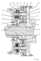
- the only figure shows a hydraulically operated Coupling unit, in which the pressure pieces with the Disc springs are connected so that they are in the depressurized state the actuators no forces on the slats who can exercise clutches.
- a first Ariebiebteil 1 can via a clutch 2nd be connected to an output part 3.
- a second drive part 4 can via a clutch 5 with an output part 3 can be connected.
- the clutch 2 via the actuating device 6 the clutch 2 can be opened or closed via the actuating device 7 can open the clutch 5 or be closed.
- the actuator 6 there is a piston 8, which is under pressure axially displaced by the feed 9 so that it comes into contact with one or more pressure pieces 10 and this thrust piece 10 moves axially so that the clutch 2 against the spring force of the spring 11 in the closing direction is operated.
- the pressure piece 10 is in an area 13 in the Opening 12 of the plate spring 11 inserted.
- the speed-dependent forces from the hydraulic fluid, which are in room 15 and act on the pressure piece 10, are based on the Area 14 of the pressure piece 10 on the plate spring 11.
- the Room 15 has only openings, which with a feed 17 are connected, through which the slats of the Couplings 2 and 5 are lubricated and cooled. Otherwise room 15 is closed. This prevents that from the room 15 coolant and lubricant of the fins drains permanently and thus only the couplings a reduced amount of cooling and lubrication is available stands.
- the actuating device 7 has a comparable one Building on. By pressurizing the actuator 6 or 7 becomes hydraulic fluid from room 15 or 18 additionally pushed into the feed 17 so that when closing the clutches 2 or 5 additional cooling or Lubricant is available.
- the pressure medium supply Room 15 also has the option of Room 15 to generate a regulated back pressure, which counteracts the actuation pressure in room 16 and via which thus generates a controlled torque on the clutch 2 can be.
- the clutches 2 and 5 and the Actuators 6 and 7 in the same axial area can be arranged radially one above the other the coupling unit can be made very compact.
- disc springs 11 and 19, which are radial Have openings, and pressure pieces 10 and 20, which in these openings can be hooked in hydraulically actuated clutch are created, in which in the unpressurized Condition no forces act on the clutch and the clutch stands out through the use of very few components distinguished.
Landscapes
- Engineering & Computer Science (AREA)
- General Engineering & Computer Science (AREA)
- Mechanical Engineering (AREA)
- Hydraulic Clutches, Magnetic Clutches, Fluid Clutches, And Fluid Joints (AREA)
- Mechanical Operated Clutches (AREA)
Applications Claiming Priority (2)
| Application Number | Priority Date | Filing Date | Title |
|---|---|---|---|
| DE19919780A DE19919780A1 (de) | 1999-04-30 | 1999-04-30 | Hydraulisch betätigbare Kupplung |
| DE19919780 | 1999-04-30 |
Publications (3)
| Publication Number | Publication Date |
|---|---|
| EP1048867A2 true EP1048867A2 (fr) | 2000-11-02 |
| EP1048867A3 EP1048867A3 (fr) | 2002-01-16 |
| EP1048867B1 EP1048867B1 (fr) | 2006-05-17 |
Family
ID=7906466
Family Applications (1)
| Application Number | Title | Priority Date | Filing Date |
|---|---|---|---|
| EP00108710A Expired - Lifetime EP1048867B1 (fr) | 1999-04-30 | 2000-04-22 | Embrayage à commande hydraulique |
Country Status (3)
| Country | Link |
|---|---|
| EP (1) | EP1048867B1 (fr) |
| AT (1) | ATE326648T1 (fr) |
| DE (2) | DE19919780A1 (fr) |
Cited By (1)
| Publication number | Priority date | Publication date | Assignee | Title |
|---|---|---|---|---|
| DE10055958A1 (de) * | 2000-11-11 | 2002-05-23 | Zahnradfabrik Friedrichshafen | Rotierende Kupplung mit Rotationsausgleich |
Families Citing this family (1)
| Publication number | Priority date | Publication date | Assignee | Title |
|---|---|---|---|---|
| DE102004034737B4 (de) * | 2003-12-11 | 2014-03-06 | Zf Friedrichshafen Ag | Hydraulisch betätigbare Lamellenkupplung |
Family Cites Families (13)
| Publication number | Priority date | Publication date | Assignee | Title |
|---|---|---|---|---|
| DE639052C (de) * | 1936-11-27 | Franz Jordan Dr Ing | Druckluftgesteuerte Lamellenreibungskupplung | |
| US3863746A (en) * | 1973-03-30 | 1975-02-04 | Caterpillar Tractor Co | Centrifugally balanced rotating clutch |
| US3858698A (en) * | 1973-05-16 | 1975-01-07 | Gen Motors Corp | Unitary spring for stroking transmission servo motor |
| DE2605228A1 (de) * | 1976-02-11 | 1977-08-18 | Zahnradfabrik Friedrichshafen | Druckmittelbetaetigte mehrscheibenkupplung |
| JPH0781594B2 (ja) * | 1985-08-31 | 1995-08-30 | 三菱自動車工業株式会社 | 動力伝達装置 |
| US4724941A (en) * | 1986-12-22 | 1988-02-16 | General Motors Corporation | Multi-capacity friction device |
| DE3819702A1 (de) * | 1988-06-09 | 1989-12-14 | Porsche Ag | Hydraulisch betaetigte doppelkupplung fuer ein kraftfahrzeug |
| US4945782A (en) * | 1989-04-28 | 1990-08-07 | General Motors Corporation | Mounting device for securing a ring gear to a drive drum |
| US5172799A (en) * | 1991-02-08 | 1992-12-22 | Toyota Jidosha Kabushiki Kaisha | Centrifugal hydraulic cancel mechanism for the rotating clutch |
| DE4341953A1 (de) * | 1993-12-09 | 1995-01-26 | Daimler Benz Ag | Anordnung eines ringförmigen Axialkolbens eines Kupplungsstellgliedes bei einer Lamellenkupplung |
| JP3354303B2 (ja) * | 1994-08-19 | 2002-12-09 | 本田技研工業株式会社 | タンデム型油圧クラッチ |
| JP3571896B2 (ja) * | 1997-12-11 | 2004-09-29 | ジヤトコ株式会社 | 自動変速機の油圧締結装置 |
| DE19821164B4 (de) * | 1998-05-12 | 2008-04-17 | Volkswagen Ag | Doppelkupplungsgetriebe |
-
1999
- 1999-04-30 DE DE19919780A patent/DE19919780A1/de not_active Withdrawn
-
2000
- 2000-04-22 DE DE50012747T patent/DE50012747D1/de not_active Expired - Lifetime
- 2000-04-22 EP EP00108710A patent/EP1048867B1/fr not_active Expired - Lifetime
- 2000-04-22 AT AT00108710T patent/ATE326648T1/de not_active IP Right Cessation
Cited By (1)
| Publication number | Priority date | Publication date | Assignee | Title |
|---|---|---|---|---|
| DE10055958A1 (de) * | 2000-11-11 | 2002-05-23 | Zahnradfabrik Friedrichshafen | Rotierende Kupplung mit Rotationsausgleich |
Also Published As
| Publication number | Publication date |
|---|---|
| EP1048867A3 (fr) | 2002-01-16 |
| DE19919780A1 (de) | 2000-11-02 |
| EP1048867B1 (fr) | 2006-05-17 |
| DE50012747D1 (de) | 2006-06-22 |
| ATE326648T1 (de) | 2006-06-15 |
Similar Documents
| Publication | Publication Date | Title |
|---|---|---|
| DE102010006569B4 (de) | Zweiwege-Aktuatorvorrichtung in einer Drehmomentübertragungsanordnung | |
| DE102015213874A1 (de) | Axiale Lamellenkupplung | |
| EP3186525B1 (fr) | Embrayage double | |
| DE1575925B1 (de) | Hydraulisch betaetigbare Scheiben-Reibungskupplung,insbesondere Doppelkupplung | |
| DE102011006027A1 (de) | Ölzuführnabe für eine nasslaufende Doppelkupplung | |
| EP1143160A2 (fr) | Ensemble à embrayage double | |
| DE102010021899B4 (de) | Kupplung, insbesondere Doppelkupplung | |
| DE102013213983A1 (de) | Doppelkupplung | |
| DE102008036852B4 (de) | Mehrfach-Kupplungseinrichtung mit Fliehölausgleich | |
| DE4405344B4 (de) | Reibungskupplung | |
| DE102009007828B4 (de) | Reibungskupplung | |
| DE102008038100A1 (de) | Lamellenkupplung mit einem hydraulisch antreibbaren Betätigungskolben | |
| DE102015213873B4 (de) | Axiale Lamellenkupplung | |
| DE3024816A1 (de) | Scheibenkupplung | |
| DE3444103A1 (de) | Druckmittelbetaetigbare schaltkupplung | |
| EP1437534A2 (fr) | Transmission planétaire avec un embrayage et un frein à actuateur commun | |
| DE102005039272A1 (de) | Kopplungsvorrichtung | |
| EP1048867A2 (fr) | Embrayage à commande hydraulique | |
| DE19919779A1 (de) | Hydraulisch betätigbare Kupplung | |
| DE102006059072B4 (de) | Vorrichtung und Verfahren zum Betätigen einer Kupplung | |
| DE102014217277A1 (de) | Doppelkupplung | |
| DE102019118347B3 (de) | Drucktopf zum Betätigen einer Reibungskupplung | |
| EP2041444B1 (fr) | Embrayage à huile hydraulique | |
| DE2549714B1 (de) | Reibungskupplungs- und Bremsvorrichtung | |
| DE102014217279A1 (de) | Doppelkupplung |
Legal Events
| Date | Code | Title | Description |
|---|---|---|---|
| PUAI | Public reference made under article 153(3) epc to a published international application that has entered the european phase |
Free format text: ORIGINAL CODE: 0009012 |
|
| AK | Designated contracting states |
Kind code of ref document: A2 Designated state(s): AT BE CH CY DE DK ES FI FR GB GR IE IT LI LU MC NL PT SE Kind code of ref document: A2 Designated state(s): AT DE FR GB IT |
|
| AX | Request for extension of the european patent |
Free format text: AL;LT;LV;MK;RO;SI |
|
| PUAL | Search report despatched |
Free format text: ORIGINAL CODE: 0009013 |
|
| AK | Designated contracting states |
Kind code of ref document: A3 Designated state(s): AT BE CH CY DE DK ES FI FR GB GR IE IT LI LU MC NL PT SE |
|
| AX | Request for extension of the european patent |
Free format text: AL;LT;LV;MK;RO;SI |
|
| RIC1 | Information provided on ipc code assigned before grant |
Free format text: 7F 16D 25/0638 A, 7F 16D 25/12 B |
|
| 17P | Request for examination filed |
Effective date: 20011213 |
|
| AKX | Designation fees paid |
Free format text: AT DE FR GB IT |
|
| GRAP | Despatch of communication of intention to grant a patent |
Free format text: ORIGINAL CODE: EPIDOSNIGR1 |
|
| GRAS | Grant fee paid |
Free format text: ORIGINAL CODE: EPIDOSNIGR3 |
|
| GRAA | (expected) grant |
Free format text: ORIGINAL CODE: 0009210 |
|
| AK | Designated contracting states |
Kind code of ref document: B1 Designated state(s): AT DE FR GB IT |
|
| PG25 | Lapsed in a contracting state [announced via postgrant information from national office to epo] |
Ref country code: IT Free format text: LAPSE BECAUSE OF FAILURE TO SUBMIT A TRANSLATION OF THE DESCRIPTION OR TO PAY THE FEE WITHIN THE PRESCRIBED TIME-LIMIT;WARNING: LAPSES OF ITALIAN PATENTS WITH EFFECTIVE DATE BEFORE 2007 MAY HAVE OCCURRED AT ANY TIME BEFORE 2007. THE CORRECT EFFECTIVE DATE MAY BE DIFFERENT FROM THE ONE RECORDED. Effective date: 20060517 |
|
| REG | Reference to a national code |
Ref country code: GB Ref legal event code: FG4D Free format text: NOT ENGLISH |
|
| REF | Corresponds to: |
Ref document number: 50012747 Country of ref document: DE Date of ref document: 20060622 Kind code of ref document: P |
|
| GBT | Gb: translation of ep patent filed (gb section 77(6)(a)/1977) |
Effective date: 20060713 |
|
| ET | Fr: translation filed | ||
| PLBE | No opposition filed within time limit |
Free format text: ORIGINAL CODE: 0009261 |
|
| STAA | Information on the status of an ep patent application or granted ep patent |
Free format text: STATUS: NO OPPOSITION FILED WITHIN TIME LIMIT |
|
| 26N | No opposition filed |
Effective date: 20070220 |
|
| GBPC | Gb: european patent ceased through non-payment of renewal fee |
Effective date: 20070422 |
|
| PG25 | Lapsed in a contracting state [announced via postgrant information from national office to epo] |
Ref country code: GB Free format text: LAPSE BECAUSE OF NON-PAYMENT OF DUE FEES Effective date: 20070422 |
|
| PG25 | Lapsed in a contracting state [announced via postgrant information from national office to epo] |
Ref country code: FR Free format text: LAPSE BECAUSE OF NON-PAYMENT OF DUE FEES Effective date: 20070430 |
|
| PG25 | Lapsed in a contracting state [announced via postgrant information from national office to epo] |
Ref country code: AT Free format text: LAPSE BECAUSE OF NON-PAYMENT OF DUE FEES Effective date: 20070422 |
|
| PGFP | Annual fee paid to national office [announced via postgrant information from national office to epo] |
Ref country code: DE Payment date: 20100430 Year of fee payment: 11 |
|
| REG | Reference to a national code |
Ref country code: DE Ref legal event code: R119 Ref document number: 50012747 Country of ref document: DE |
|
| REG | Reference to a national code |
Ref country code: DE Ref legal event code: R119 Ref document number: 50012747 Country of ref document: DE |
|
| PG25 | Lapsed in a contracting state [announced via postgrant information from national office to epo] |
Ref country code: DE Free format text: LAPSE BECAUSE OF NON-PAYMENT OF DUE FEES Effective date: 20111031 |