EP1048896A1 - Montageverfahren einer Einbauleuchte in eine Deckenplatte und dafür geeignete Hülse - Google Patents
Montageverfahren einer Einbauleuchte in eine Deckenplatte und dafür geeignete Hülse Download PDFInfo
- Publication number
- EP1048896A1 EP1048896A1 EP00303644A EP00303644A EP1048896A1 EP 1048896 A1 EP1048896 A1 EP 1048896A1 EP 00303644 A EP00303644 A EP 00303644A EP 00303644 A EP00303644 A EP 00303644A EP 1048896 A1 EP1048896 A1 EP 1048896A1
- Authority
- EP
- European Patent Office
- Prior art keywords
- sleeve member
- opening
- ceiling panel
- fitting
- sleeve
- Prior art date
- Legal status (The legal status is an assumption and is not a legal conclusion. Google has not performed a legal analysis and makes no representation as to the accuracy of the status listed.)
- Granted
Links
- 238000000034 method Methods 0.000 title claims abstract description 17
- 238000003780 insertion Methods 0.000 claims description 5
- 230000037431 insertion Effects 0.000 claims description 5
- 230000000717 retained effect Effects 0.000 claims description 3
- 229910052602 gypsum Inorganic materials 0.000 abstract description 9
- 239000010440 gypsum Substances 0.000 abstract description 9
- 239000000463 material Substances 0.000 description 10
- 230000009970 fire resistant effect Effects 0.000 description 2
- 230000002787 reinforcement Effects 0.000 description 2
- 239000000779 smoke Substances 0.000 description 2
- 229910000639 Spring steel Inorganic materials 0.000 description 1
- 229910000831 Steel Inorganic materials 0.000 description 1
- 239000004411 aluminium Substances 0.000 description 1
- 229910052782 aluminium Inorganic materials 0.000 description 1
- XAGFODPZIPBFFR-UHFFFAOYSA-N aluminium Chemical compound [Al] XAGFODPZIPBFFR-UHFFFAOYSA-N 0.000 description 1
- 239000011248 coating agent Substances 0.000 description 1
- 238000000576 coating method Methods 0.000 description 1
- 229910052751 metal Inorganic materials 0.000 description 1
- 239000002184 metal Substances 0.000 description 1
- 230000002265 prevention Effects 0.000 description 1
- 239000012858 resilient material Substances 0.000 description 1
- 239000010959 steel Substances 0.000 description 1
- 230000001629 suppression Effects 0.000 description 1
- XLYOFNOQVPJJNP-UHFFFAOYSA-N water Substances O XLYOFNOQVPJJNP-UHFFFAOYSA-N 0.000 description 1
- 239000002023 wood Substances 0.000 description 1
Images


Classifications
-
- F—MECHANICAL ENGINEERING; LIGHTING; HEATING; WEAPONS; BLASTING
- F21—LIGHTING
- F21V—FUNCTIONAL FEATURES OR DETAILS OF LIGHTING DEVICES OR SYSTEMS THEREOF; STRUCTURAL COMBINATIONS OF LIGHTING DEVICES WITH OTHER ARTICLES, NOT OTHERWISE PROVIDED FOR
- F21V21/00—Supporting, suspending, or attaching arrangements for lighting devices; Hand grips
- F21V21/02—Wall, ceiling, or floor bases; Fixing pendants or arms to the bases
- F21V21/04—Recessed bases
Definitions
- This invention relates to a method of mounting a fitting to a ceiling panel, and to a sleeve member therefor.
- the invention is likely to find its greatest utility in relation to the mounting of light fittings into ceiling panels, for example ceiling panels of gypsum, and much of the following description will therefore relate to such use.
- the use for mounting another fitting such as a smoke detector for example, or for use with ceiling panels of other materials, is not thereby excluded.
- the beams are covered by floor boarding above, and by ceiling panels below.
- the ceiling panels may be secured directly to the beams, or else there may be a suspended or false ceiling in which the ceiling panels are spaced from the beams.
- Fire is a recognised concern in buildings, and the builder and/or designer will usually take precautions and incorporate design features intended to reduce the likelihood of fire taking place, and/or to reduce the severity of any fire which does take place. It is a recognised problem that the space between the beams, and perhaps between the beams and the ceiling panels if there is a false or suspended ceiling, can harbour and promote fire, i.e. a fire can enter into this space and spread throughout large areas of the building, substantially protected from water or other fire suppression means which might be used to seek to extinguish the fire.
- ceiling panels are designed to withstand fire for a limited period of time, perhaps one hour or more.
- fittings such as light fittings, smoke detectors and other devices
- any opening through a ceiling panel presents a possible path for fire to enter above the ceiling panels and between the beams, and so ideally the fitting must itself be at least as fire resistant as the ceiling panel and so effectively seal the opening.
- the fitting is itself fire resistant, the weight of the fitting might itself cause the ceiling panel adjacent the opening to fracture and give way, especially in the presence of intense heat caused by an adjacent fire. In this way, the fitting can indirectly cause the ceiling panel integrity to be lost.
- a light fitting designed for use in fire-rated ceilings, particularly suspended ceilings, is disclosed in my patent application WO97/13999.
- a support member for a light fitting for use in suspended ceilings is disclosed in my patent applications WO97/13999 and WO98/12472.
- a method of mounting a fitting to a ceiling panel comprising the steps of ⁇ i ⁇ forming an opening in the ceiling panel, ⁇ ii ⁇ inserting a sleeve member through the opening, the sleeve member having a flange for abutment with a first surface of the ceiling panel adjacent the opening, ⁇ iii ⁇ moving a part of the sleeve into engagement with a second surface of the celing panel adjacent the opening, and ⁇ iv ⁇ mounting the fitting into the sleeve.
- the fitting such as a light fitting or the like can be mounted into the sleeve, which will be sized to receive the fitting.
- the sleeve member may be resilient, and may be compressed prior to its insertion into the opening, thereafter resiliently to expand into engagement with the first and second surfaces of the ceiling panel.
- the sleeve member is substantially non-resilient and deformable, and preferably includes a part or parts adapted to be deformed following fitment of the sleeve member into the opening.
- the sleeve member has parts adapted to be deformed around the full extent of the opening.
- parts of the sleeve are deformed so as to lie upon the second surface of the ceiling panel. Notwithstanding that the deformed parts of the sleeve will usually not totally cover the second surface of the ceiling panel adjacent the opening, they will provide added reinforcement to the ceiling panel surrounding the opening, and will act to spread the load of the fitting across a greater area of the ceiling panel, so that the panel is better able to withstand heat and fire.
- the method can include the additional step of ⁇ ia ⁇ inserting a support member through the opening and positioning this to have a portion adjacent the opening, and ⁇ iiia ⁇ ensuring that whilst the sleeve is moved, the portion of the support member is retained thereby.
- the support member will be retained by the sleeve member, for example being held between the moved or deformed part of the sleeve member and the second surface of the ceiling panel.
- the weight of the fitting can be spread over an even greater area of the ceiling panel, corresponding approximately to the size of the support member.
- the support member can be adapted to engage the beams or joists upon which the ceiling panel is secured.
- a sleeve member for use in the method of mounting a fitting to a ceiling panel, the sleeve member comprising a tubular part and a flange, the tubular part being sized to receive the fitting, a portion of the tubular part being cut to provide a movable or deformable part.
- the tubular part is cut in several places, to provide several movable or deformable parts.
- the flange is continuous around one end of the sleeve member.
- the sleeve member 10 is manufactured of metal, suitably steel or aluminium.
- the sleeve member is coated all over with an intumescent material, i.e. a material which expands in the presence of heat, so as to provide a fire-proof seal around the sleeve member.
- the intumescent material may suitably be painted on to the sleeve member 10.
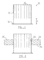
- the sleeve member comprises a tube portion 12 with a flange 14 at one end. At the end opposed to the flange the tube has been cut to form a number of fingers 16.
- the length 1 of the tube portion which is not cut corresponds approximately to the thickness of the ceiling panel, i.e. it is not necessary, or preferred, to cut the tube portion 12 more than is necessary to permit the fingers 16 to be deformed to overlie the upper surface of the ceiling panel in use.
- the overall length of the tube portion can be chosen to suit the requirements, e.g. a longer tube portion providing longer fingers which in use will overlie a greater area of the ceiling panel.
- the tube portion 12 of the sleeve member may be inserted through an opening 20 created in the ceiling panel 22 (Fig.2), the size of the tube portion being predetermined to be a close sliding fit within the opening 20.
- the flange 14 is larger than the opening 20 and so limits the insertion of the tube portion.
- the sleeve member 10 should be made of a material which is thick enough and strong enough so that the fingers 16 are able to support the weight of the fitting after they have been bent to overlie the ceiling panel (including in the presence of extreme heat), but also be able to be bent to that position by the installer, without undue difficulty, and ideally without the use of specialist tools.
- the sleeve will present an aperture 30 (Fig.3) of predetermined size for receiving a fitting such as a light fitting 32 (Fig.6).
- Fig.6 shows the sleeve member 10 prior to deformation of the fingers 16 into engagement with the ceiling panel 22; in practice the fingers 16 would be deformed prior to insertion of the fitting 32.
- the light fitting 32 carries a mounting means in the form of two springs 34 (Figs. 6,7), which are of known form. Following insertion of the light fitting 32 into the aperture 30, the springs 34 are resiliently biassed outwardly and engage upon the second surface 26 of the ceiling panel 22. It will be understood that in normal conditions it is the springs 34 which support the weight of the light fitting 32 and maintain it in contact with the ceiling panel 22; in the absence of fire the fingers 16 are not performing any supporting function.
- a sleeve member similar to that of Figs. 1-3 can extend the time for which the ceiling panel can resist the breakthrough of fire, i.e. can extend the time before the gypsum adjacent the opening breaks down suffiently for the light fitting to fall out.
- the springs 34 which lie above the fingers 16 in the position of use (Fig.7) will engage the sleeve member 10 before the light fitting falls out of the aperture.
- the fingers 16 support the gypsum immediately adjacent the opening 20 and act to spread the load of the light fitting over a relatively large area of the ceiling panel 22.
- the aperture 30 in this embodiment is circular and does not contain any discontinuities or deformations; however in other embodiments the aperture 30 created by the fitted sleeve member 10 can be other than circular, and can contain discontinuities or deformations suitable to receive and cooperate with a part or parts of the fitting to enable ease of mounting of the fitting.
- a support member 36 such as that of Figs. 4 and 5 can be used. As described below, the support member 36 acts to spread the load of the fitting over an even greater area of the ceiling panel 22, and perhaps can even engage the beams or other support structure of the ceiling panels.
- the support member 36 of Figs. 4 and 5 comprises a length of spring steel wire.
- the support member is of circular cross section, 2 mm in diameter, and has an overall length L of approximately 700 mm (though other cross sections and overall lengths could be used to suit the particular application).
- the support member 36 At the approximate centre of the support member 36 it is bent into a part-circular shape 40, the diameter of which is sized to be slightly larger than the diameter of the opening 20. Accordingly, when the support member is placed adjacent the opening 20, the fingers 16 of the sleeve member 10 can be bent over part or all of the part-circular shape 40, trapping that part of the support member 36 between the fingers 16 and the ceiling panel 22.
- the support member 36 the ends of which perhaps engage the beams or support structure of the ceiling. Even if the support member 36 does not engage the beams or support structure of the ceiling, it will be understood that the length of the support member acts to spread the load of the fitting 32 over a far greater area of the ceiling panel 22.
- a support member may not be required.
- one or more support members 36 may be used with a single sleeve member as desired or required to suit the application.
- two support members 42,44 may be substantially orthogonally arranged, as shown in Fig.7. It will be understood that the support members 42,44 of Fig.7 are not identical to the support member 36 of Figs. 4 and 5. Thus, several different forms of support member would be possible to fulfil the requirements for this component.
- the support member it is not necessary that the support member have a part-circular shape adjacent its centre, the shape could be other than part-circular, provided that it could be engaged by at least some of the fingers 16 of the sleeve member.
- Figs. 8 and 9 show an alternative design of sleeve member, which is made of resilient material, again coated with an intumescent material.
- the fingers 116 are preformed, and are spaced from the flange 114 by a distance approximately equal to the thickness of the ceiling panel to which it is to be fitted.
- the sleeve member is split at 100, and this split allows the sleeve member to be compressed so as to reduce its overall diameter D so that it may be inserted into the opening 20 in the ceiling panel 22.
- the sleeve member has been appropriately positioned within the opening 20 it is released, and its resilience causes it to expand, with the fingers 16 lying against the surface 26 of the panel 22, and the flange 14 lying against the surface 24 of the panel.
- the fingers 16 may be arranged to trap and retain a part of a support member as above described, if desired.
- the sleeve member may be made in two halves, i.e. effectively with two splits 100, each half being inserted into the opening separately, but both halves together substantially completely surrounding the opening.
- the fingers 116 could of course be replaced by a continuous flange similar to the flange 114. However, this is not believed to be necessary since the discrete fingers have been found to provide adequate additional support to the ceiling panel.
- test number TE92663 conducted by The Loss Prevention Council, Melrose Avenue, Borehamwood, WD6 2BJ, England, on 19 April 1999
- a gypsum ceiling panel having a light fitting mounted therein was subjected to a fire test.
- the light fitting was supported within a sleeve member similar to that of Figs. 1-3, which was itself supported by a support member similar to that of Figs. 4 and 5.
- the support member was of "Ocean Brand" (TM) fire grade 3 wire provided by Webster & Horsfall, Hay Mills, Birmingham, B25 8DW, and was coated with intumescent material.
- the ceiling panel passed a 1.5 hour fire test.
Landscapes
- Engineering & Computer Science (AREA)
- General Engineering & Computer Science (AREA)
- Building Environments (AREA)
- Non-Portable Lighting Devices Or Systems Thereof (AREA)
- Residential Or Office Buildings (AREA)
- Vehicle Interior And Exterior Ornaments, Soundproofing, And Insulation (AREA)
Applications Claiming Priority (2)
| Application Number | Priority Date | Filing Date | Title |
|---|---|---|---|
| GBGB9909844.4A GB9909844D0 (en) | 1999-04-30 | 1999-04-30 | Method of mounting a fitting to a ceiling panel,and sleeve member therefor |
| GB9909844 | 1999-04-30 |
Publications (2)
| Publication Number | Publication Date |
|---|---|
| EP1048896A1 true EP1048896A1 (de) | 2000-11-02 |
| EP1048896B1 EP1048896B1 (de) | 2008-03-19 |
Family
ID=10852453
Family Applications (1)
| Application Number | Title | Priority Date | Filing Date |
|---|---|---|---|
| EP00303644A Expired - Lifetime EP1048896B1 (de) | 1999-04-30 | 2000-04-28 | Montageverfahren einer Einbauleuchte in eine Deckenplatte und dafür geeignete Hülse |
Country Status (4)
| Country | Link |
|---|---|
| EP (1) | EP1048896B1 (de) |
| AT (1) | ATE389851T1 (de) |
| DE (1) | DE60038331D1 (de) |
| GB (1) | GB9909844D0 (de) |
Cited By (6)
| Publication number | Priority date | Publication date | Assignee | Title |
|---|---|---|---|---|
| GB2421070A (en) * | 2005-01-27 | 2006-06-14 | Rd Europe Ltd | Fire-Resistant over for Lighting Fitting |
| GB2468699A (en) * | 2009-03-19 | 2010-09-22 | Warren Hickson | Fire proof light fitting |
| FR3020443A1 (fr) * | 2014-04-24 | 2015-10-30 | Legrand France | Element annulaire et procede de realisation d'un tel element annulaire |
| GB2526144A (en) * | 2014-05-16 | 2015-11-18 | Mark Richard Stevens | Aperture liner |
| US9677747B2 (en) | 2014-06-02 | 2017-06-13 | RAB Lighting Inc. | Ceiling cutout collar and remodel light fixture |
| WO2023245224A1 (en) * | 2022-06-20 | 2023-12-28 | Watson Kevin Jason | A collar |
Citations (6)
| Publication number | Priority date | Publication date | Assignee | Title |
|---|---|---|---|---|
| BE631841A (de) * | ||||
| NL8201576A (nl) * | 1982-04-15 | 1983-11-01 | Hiemstra Evolux Bv | In een kap van een lichtbron of dergelijke te gebruiken ring. |
| US4885665A (en) * | 1989-01-09 | 1989-12-05 | Benjamin Birillo | Triangular electric ceiling fixture |
| WO1997013999A1 (en) | 1995-10-13 | 1997-04-17 | Peter Charles Jones | Lamp assembly mounting |
| WO1998012472A1 (en) | 1996-09-20 | 1998-03-26 | Peter Charles Jones | Installation of lighting or other fittings in ceilings |
| FR2770619A1 (fr) * | 1997-10-31 | 1999-05-07 | Guy Hosteing | Dispositif de montage d'un spot dans un faux plafond |
-
1999
- 1999-04-30 GB GBGB9909844.4A patent/GB9909844D0/en not_active Ceased
-
2000
- 2000-04-28 DE DE60038331T patent/DE60038331D1/de not_active Expired - Lifetime
- 2000-04-28 AT AT00303644T patent/ATE389851T1/de not_active IP Right Cessation
- 2000-04-28 EP EP00303644A patent/EP1048896B1/de not_active Expired - Lifetime
Patent Citations (6)
| Publication number | Priority date | Publication date | Assignee | Title |
|---|---|---|---|---|
| BE631841A (de) * | ||||
| NL8201576A (nl) * | 1982-04-15 | 1983-11-01 | Hiemstra Evolux Bv | In een kap van een lichtbron of dergelijke te gebruiken ring. |
| US4885665A (en) * | 1989-01-09 | 1989-12-05 | Benjamin Birillo | Triangular electric ceiling fixture |
| WO1997013999A1 (en) | 1995-10-13 | 1997-04-17 | Peter Charles Jones | Lamp assembly mounting |
| WO1998012472A1 (en) | 1996-09-20 | 1998-03-26 | Peter Charles Jones | Installation of lighting or other fittings in ceilings |
| FR2770619A1 (fr) * | 1997-10-31 | 1999-05-07 | Guy Hosteing | Dispositif de montage d'un spot dans un faux plafond |
Cited By (11)
| Publication number | Priority date | Publication date | Assignee | Title |
|---|---|---|---|---|
| GB2421070A (en) * | 2005-01-27 | 2006-06-14 | Rd Europe Ltd | Fire-Resistant over for Lighting Fitting |
| EP1686315A1 (de) * | 2005-01-27 | 2006-08-02 | RD Europe Limited | Feuerfeste Abdeckung für eine Leuchte |
| GB2421070B (en) * | 2005-01-27 | 2007-01-10 | Rd Europe Ltd | Fire-resistant cover for lighting fitting |
| GB2468699A (en) * | 2009-03-19 | 2010-09-22 | Warren Hickson | Fire proof light fitting |
| FR3020443A1 (fr) * | 2014-04-24 | 2015-10-30 | Legrand France | Element annulaire et procede de realisation d'un tel element annulaire |
| GB2526144A (en) * | 2014-05-16 | 2015-11-18 | Mark Richard Stevens | Aperture liner |
| WO2015173593A3 (en) * | 2014-05-16 | 2016-01-07 | Stevens Mark Richard | Aperture liner |
| GB2548182A (en) * | 2014-05-16 | 2017-09-13 | Richard Stevens Mark | Aperture liner |
| GB2548182B (en) * | 2014-05-16 | 2021-08-11 | Richard Stevens Mark | Aperture liner |
| US9677747B2 (en) | 2014-06-02 | 2017-06-13 | RAB Lighting Inc. | Ceiling cutout collar and remodel light fixture |
| WO2023245224A1 (en) * | 2022-06-20 | 2023-12-28 | Watson Kevin Jason | A collar |
Also Published As
| Publication number | Publication date |
|---|---|
| ATE389851T1 (de) | 2008-04-15 |
| GB9909844D0 (en) | 1999-06-23 |
| DE60038331D1 (de) | 2008-04-30 |
| EP1048896B1 (de) | 2008-03-19 |
Similar Documents
| Publication | Publication Date | Title |
|---|---|---|
| US7856775B2 (en) | Thermal insulation and sealing means for a safing slot | |
| Dhakal et al. | Seismic fragility of suspended ceiling systems used in NZ based on component tests | |
| EP0908668A2 (de) | Feuerbeständiges Leuchtengehäuse | |
| AU2014361786B2 (en) | Drywall joist hanger connection | |
| CA2684179C (en) | Methods and apparatuses for positioning and securing safing insulation | |
| US10309100B2 (en) | Mullion cover hanger and curtain wall insulation system incorporating the same | |
| US20250122717A1 (en) | Insulation mounting bracket | |
| EP1048896B1 (de) | Montageverfahren einer Einbauleuchte in eine Deckenplatte und dafür geeignete Hülse | |
| CA3178857A1 (en) | Insulation mounting bracket | |
| AU2025275329A1 (en) | Curtain wall insulation system | |
| US20160060862A1 (en) | Modular joint barrier retainer assembly and method | |
| Phan et al. | State of the art report on seismic design requirements for nonstructural building components | |
| JP6225059B2 (ja) | 天井の落下防止構造 | |
| CN108316538B (zh) | 吊顶系统 | |
| JPH10219888A (ja) | 防煙垂れ壁の取付構造 | |
| CA3178870C (en) | Insulation mounting bracket | |
| KR200280432Y1 (ko) | 고정부재를 갖는 방화 및 방음보드장치 | |
| KR102336057B1 (ko) | 내풍압용 천장 보강대와 이를 이용한 시공방법 | |
| JP3960364B2 (ja) | 消火設備 | |
| Clark et al. | Suspended ceilings: The seismic hazard and damage problem and some practical solutions | |
| EP0176233A1 (de) | Rohrhülse | |
| Merz et al. | Nonstructural component considerations | |
| Comeau | Roof collapse kills three | |
| NZ711053A (en) | Load spreading device for hollow core concrete | |
| JPH09268694A (ja) | 建物の天井支持構造 |
Legal Events
| Date | Code | Title | Description |
|---|---|---|---|
| PUAI | Public reference made under article 153(3) epc to a published international application that has entered the european phase |
Free format text: ORIGINAL CODE: 0009012 |
|
| AK | Designated contracting states |
Kind code of ref document: A1 Designated state(s): AT BE CH CY DE DK ES FI FR GB GR IE IT LI LU MC NL PT SE |
|
| AX | Request for extension of the european patent |
Free format text: AL;LT;LV;MK;RO;SI |
|
| 17P | Request for examination filed |
Effective date: 20010502 |
|
| AKX | Designation fees paid |
Free format text: AT BE CH CY DE DK ES FI FR GB GR IE IT LI LU MC NL PT SE |
|
| 17Q | First examination report despatched |
Effective date: 20060713 |
|
| 17Q | First examination report despatched |
Effective date: 20060713 |
|
| GRAP | Despatch of communication of intention to grant a patent |
Free format text: ORIGINAL CODE: EPIDOSNIGR1 |
|
| GRAS | Grant fee paid |
Free format text: ORIGINAL CODE: EPIDOSNIGR3 |
|
| GRAA | (expected) grant |
Free format text: ORIGINAL CODE: 0009210 |
|
| AK | Designated contracting states |
Kind code of ref document: B1 Designated state(s): AT BE CH CY DE DK ES FI FR GB GR IE IT LI LU MC NL PT SE |
|
| REG | Reference to a national code |
Ref country code: GB Ref legal event code: FG4D |
|
| REG | Reference to a national code |
Ref country code: CH Ref legal event code: EP |
|
| REF | Corresponds to: |
Ref document number: 60038331 Country of ref document: DE Date of ref document: 20080430 Kind code of ref document: P |
|
| REG | Reference to a national code |
Ref country code: IE Ref legal event code: FG4D |
|
| PG25 | Lapsed in a contracting state [announced via postgrant information from national office to epo] |
Ref country code: FI Free format text: LAPSE BECAUSE OF FAILURE TO SUBMIT A TRANSLATION OF THE DESCRIPTION OR TO PAY THE FEE WITHIN THE PRESCRIBED TIME-LIMIT Effective date: 20080319 |
|
| PG25 | Lapsed in a contracting state [announced via postgrant information from national office to epo] |
Ref country code: AT Free format text: LAPSE BECAUSE OF FAILURE TO SUBMIT A TRANSLATION OF THE DESCRIPTION OR TO PAY THE FEE WITHIN THE PRESCRIBED TIME-LIMIT Effective date: 20080319 |
|
| NLV1 | Nl: lapsed or annulled due to failure to fulfill the requirements of art. 29p and 29m of the patents act | ||
| PG25 | Lapsed in a contracting state [announced via postgrant information from national office to epo] |
Ref country code: BE Free format text: LAPSE BECAUSE OF FAILURE TO SUBMIT A TRANSLATION OF THE DESCRIPTION OR TO PAY THE FEE WITHIN THE PRESCRIBED TIME-LIMIT Effective date: 20080319 |
|
| PG25 | Lapsed in a contracting state [announced via postgrant information from national office to epo] |
Ref country code: DE Free format text: LAPSE BECAUSE OF FAILURE TO SUBMIT A TRANSLATION OF THE DESCRIPTION OR TO PAY THE FEE WITHIN THE PRESCRIBED TIME-LIMIT Effective date: 20080620 Ref country code: ES Free format text: LAPSE BECAUSE OF FAILURE TO SUBMIT A TRANSLATION OF THE DESCRIPTION OR TO PAY THE FEE WITHIN THE PRESCRIBED TIME-LIMIT Effective date: 20080630 Ref country code: SE Free format text: LAPSE BECAUSE OF FAILURE TO SUBMIT A TRANSLATION OF THE DESCRIPTION OR TO PAY THE FEE WITHIN THE PRESCRIBED TIME-LIMIT Effective date: 20080619 Ref country code: PT Free format text: LAPSE BECAUSE OF FAILURE TO SUBMIT A TRANSLATION OF THE DESCRIPTION OR TO PAY THE FEE WITHIN THE PRESCRIBED TIME-LIMIT Effective date: 20080826 |
|
| PG25 | Lapsed in a contracting state [announced via postgrant information from national office to epo] |
Ref country code: MC Free format text: LAPSE BECAUSE OF NON-PAYMENT OF DUE FEES Effective date: 20080430 Ref country code: NL Free format text: LAPSE BECAUSE OF FAILURE TO SUBMIT A TRANSLATION OF THE DESCRIPTION OR TO PAY THE FEE WITHIN THE PRESCRIBED TIME-LIMIT Effective date: 20080319 |
|
| REG | Reference to a national code |
Ref country code: CH Ref legal event code: PL |
|
| PGFP | Annual fee paid to national office [announced via postgrant information from national office to epo] |
Ref country code: GB Payment date: 20080604 Year of fee payment: 9 |
|
| EN | Fr: translation not filed | ||
| PLBE | No opposition filed within time limit |
Free format text: ORIGINAL CODE: 0009261 |
|
| STAA | Information on the status of an ep patent application or granted ep patent |
Free format text: STATUS: NO OPPOSITION FILED WITHIN TIME LIMIT |
|
| PG25 | Lapsed in a contracting state [announced via postgrant information from national office to epo] |
Ref country code: DK Free format text: LAPSE BECAUSE OF FAILURE TO SUBMIT A TRANSLATION OF THE DESCRIPTION OR TO PAY THE FEE WITHIN THE PRESCRIBED TIME-LIMIT Effective date: 20080319 Ref country code: LI Free format text: LAPSE BECAUSE OF NON-PAYMENT OF DUE FEES Effective date: 20080430 Ref country code: CH Free format text: LAPSE BECAUSE OF NON-PAYMENT OF DUE FEES Effective date: 20080430 |
|
| 26N | No opposition filed |
Effective date: 20081222 |
|
| PG25 | Lapsed in a contracting state [announced via postgrant information from national office to epo] |
Ref country code: IE Free format text: LAPSE BECAUSE OF NON-PAYMENT OF DUE FEES Effective date: 20080428 |
|
| PG25 | Lapsed in a contracting state [announced via postgrant information from national office to epo] |
Ref country code: IT Free format text: LAPSE BECAUSE OF FAILURE TO SUBMIT A TRANSLATION OF THE DESCRIPTION OR TO PAY THE FEE WITHIN THE PRESCRIBED TIME-LIMIT Effective date: 20080319 |
|
| PG25 | Lapsed in a contracting state [announced via postgrant information from national office to epo] |
Ref country code: CY Free format text: LAPSE BECAUSE OF FAILURE TO SUBMIT A TRANSLATION OF THE DESCRIPTION OR TO PAY THE FEE WITHIN THE PRESCRIBED TIME-LIMIT Effective date: 20080319 |
|
| GBPC | Gb: european patent ceased through non-payment of renewal fee |
Effective date: 20090428 |
|
| PG25 | Lapsed in a contracting state [announced via postgrant information from national office to epo] |
Ref country code: GB Free format text: LAPSE BECAUSE OF NON-PAYMENT OF DUE FEES Effective date: 20090428 |
|
| PG25 | Lapsed in a contracting state [announced via postgrant information from national office to epo] |
Ref country code: LU Free format text: LAPSE BECAUSE OF NON-PAYMENT OF DUE FEES Effective date: 20080428 |
|
| PG25 | Lapsed in a contracting state [announced via postgrant information from national office to epo] |
Ref country code: GR Free format text: LAPSE BECAUSE OF FAILURE TO SUBMIT A TRANSLATION OF THE DESCRIPTION OR TO PAY THE FEE WITHIN THE PRESCRIBED TIME-LIMIT Effective date: 20080620 |
|
| PG25 | Lapsed in a contracting state [announced via postgrant information from national office to epo] |
Ref country code: FR Free format text: LAPSE BECAUSE OF FAILURE TO SUBMIT A TRANSLATION OF THE DESCRIPTION OR TO PAY THE FEE WITHIN THE PRESCRIBED TIME-LIMIT Effective date: 20090109 |