EP1049083A1 - Gerät zum Lesen von und/oder Schreiben auf optischen Aufzeichnungsmedien - Google Patents
Gerät zum Lesen von und/oder Schreiben auf optischen Aufzeichnungsmedien Download PDFInfo
- Publication number
- EP1049083A1 EP1049083A1 EP00108211A EP00108211A EP1049083A1 EP 1049083 A1 EP1049083 A1 EP 1049083A1 EP 00108211 A EP00108211 A EP 00108211A EP 00108211 A EP00108211 A EP 00108211A EP 1049083 A1 EP1049083 A1 EP 1049083A1
- Authority
- EP
- European Patent Office
- Prior art keywords
- grating
- tilting
- optical
- light source
- compensation
- Prior art date
- Legal status (The legal status is an assumption and is not a legal conclusion. Google has not performed a legal analysis and makes no representation as to the accuracy of the status listed.)
- Withdrawn
Links
- 230000003287 optical effect Effects 0.000 title claims abstract description 60
- 238000000034 method Methods 0.000 claims abstract description 20
- 238000001514 detection method Methods 0.000 claims abstract description 10
- 230000004913 activation Effects 0.000 claims 1
- 238000012423 maintenance Methods 0.000 claims 1
- 230000008901 benefit Effects 0.000 description 8
- FGUUSXIOTUKUDN-IBGZPJMESA-N C1(=CC=CC=C1)N1C2=C(NC([C@H](C1)NC=1OC(=NN=1)C1=CC=CC=C1)=O)C=CC=C2 Chemical compound C1(=CC=CC=C1)N1C2=C(NC([C@H](C1)NC=1OC(=NN=1)C1=CC=CC=C1)=O)C=CC=C2 FGUUSXIOTUKUDN-IBGZPJMESA-N 0.000 description 5
- 230000000875 corresponding effect Effects 0.000 description 5
- 230000000694 effects Effects 0.000 description 5
- 230000001105 regulatory effect Effects 0.000 description 5
- 230000005540 biological transmission Effects 0.000 description 3
- 238000012937 correction Methods 0.000 description 3
- 238000004519 manufacturing process Methods 0.000 description 3
- GNFTZDOKVXKIBK-UHFFFAOYSA-N 3-(2-methoxyethoxy)benzohydrazide Chemical compound COCCOC1=CC=CC(C(=O)NN)=C1 GNFTZDOKVXKIBK-UHFFFAOYSA-N 0.000 description 2
- 230000008859 change Effects 0.000 description 2
- 238000005259 measurement Methods 0.000 description 2
- 230000007246 mechanism Effects 0.000 description 2
- 230000008569 process Effects 0.000 description 2
- 230000002411 adverse Effects 0.000 description 1
- 238000010276 construction Methods 0.000 description 1
- 238000013461 design Methods 0.000 description 1
- 238000011161 development Methods 0.000 description 1
- 230000018109 developmental process Effects 0.000 description 1
- 238000011156 evaluation Methods 0.000 description 1
- 230000001747 exhibiting effect Effects 0.000 description 1
- 238000003780 insertion Methods 0.000 description 1
- 230000037431 insertion Effects 0.000 description 1
- 238000012544 monitoring process Methods 0.000 description 1
- 238000012360 testing method Methods 0.000 description 1
Images

Classifications
-
- G—PHYSICS
- G11—INFORMATION STORAGE
- G11B—INFORMATION STORAGE BASED ON RELATIVE MOVEMENT BETWEEN RECORD CARRIER AND TRANSDUCER
- G11B7/00—Recording or reproducing by optical means, e.g. recording using a thermal beam of optical radiation by modifying optical properties or the physical structure, reproducing using an optical beam at lower power by sensing optical properties; Record carriers therefor
- G11B7/12—Heads, e.g. forming of the optical beam spot or modulation of the optical beam
- G11B7/135—Means for guiding the beam from the source to the record carrier or from the record carrier to the detector
- G11B7/1353—Diffractive elements, e.g. holograms or gratings
-
- G—PHYSICS
- G11—INFORMATION STORAGE
- G11B—INFORMATION STORAGE BASED ON RELATIVE MOVEMENT BETWEEN RECORD CARRIER AND TRANSDUCER
- G11B7/00—Recording or reproducing by optical means, e.g. recording using a thermal beam of optical radiation by modifying optical properties or the physical structure, reproducing using an optical beam at lower power by sensing optical properties; Record carriers therefor
- G11B7/08—Disposition or mounting of heads or light sources relatively to record carriers
- G11B7/09—Disposition or mounting of heads or light sources relatively to record carriers with provision for moving the light beam or focus plane for the purpose of maintaining alignment of the light beam relative to the record carrier during transducing operation, e.g. to compensate for surface irregularities of the latter or for track following
- G11B7/095—Disposition or mounting of heads or light sources relatively to record carriers with provision for moving the light beam or focus plane for the purpose of maintaining alignment of the light beam relative to the record carrier during transducing operation, e.g. to compensate for surface irregularities of the latter or for track following specially adapted for discs, e.g. for compensation of eccentricity or wobble
- G11B7/0956—Disposition or mounting of heads or light sources relatively to record carriers with provision for moving the light beam or focus plane for the purpose of maintaining alignment of the light beam relative to the record carrier during transducing operation, e.g. to compensate for surface irregularities of the latter or for track following specially adapted for discs, e.g. for compensation of eccentricity or wobble to compensate for tilt, skew, warp or inclination of the disc, i.e. maintain the optical axis at right angles to the disc
Definitions
- the present invention relates to an apparatus for reading from and/or writing to optical recording media which has a tilting-compensation device, and to a method for compensating for tilting.
- An apparatus of this type has an optical scanner having a light source for generating a light pencil for scanning a recording medium, and a focusing means for focusing the light beam generated by the light source onto the recording medium.
- the focusing means exhibits tilting with respect to the optical axis of the light beam.
- Other optical elements of the scanner may also exhibit tilting.
- some apparatuses have a tilting-detection device and a tilting-compensation device, with the aid of which the tilting of the focusing means and/or of other optical elements is compensated for.
- the compensation of the tilting has the effect of reducing the error rate when reading from and/or writing to the optical recording medium.
- This known apparatus may be regarded as having the disadvantage that, in order to be able to carry out compensation of tilting, first of all a recording medium has to be read.
- This has the disadvantage that erroneously read data occur with increased frequency until the compensation of the tilting has been concluded, and this has an adverse effect for example on the reproduction of the data.
- a relatively large degree of tilting means that it is not even possible to read from the recording medium in the first place.
- a further disadvantage may be seen in the fact that all the functions of the apparatus which are required for playback or reproduction of the recording medium are necessary for compensating for tilting. Therefore, the known method is also less suitable for tilting compensation that is to be carried out during the production process.
- the object of the present invention is to propose an apparatus and a corresponding method which enables optimum compensation of tilting using as few apparatus functions as possible.
- the tilting-detection device has an optical grating which can be introduced into the beam path of the light source at the location of the recording medium, a detector element, a control device for switching on the light source and for moving the focusing means, and a control device for evaluating the signal of the detector element and for driving the tilting-compensation device for the purpose of varying and minimizing the tilting.
- the compensation of tilting for the apparatus according to the invention is possible as early as during the production of the said apparatus, the functionality of light source and focusing means being all that is required. In an advantageous manner, their functionality is tested at the same time as the compensation of tilting or with little time between them, for example in a test cycle. However, it is possible to set the compensation of tilting permanently, that is to say to dispense with later variation of the compensation of tilting. Another possibility is to carry out compensation of tilting for example during the operation of the apparatus, after the insertion of a new recording medium, before focusing has even been effected.
- the optical grating is advantageously a separate element, but it may also be formed by the recording medium.
- the detector element may be arranged both in the transmission position and in the reflection position with respect to the optical grating. It is advantageously a cost-effective detector of simple construction whose detector area can be designed to be relatively large.
- the detector element is a detector element which is arranged on the scanner and, during operation, is designed for example for reading out the data or as part of a regulating circuit.
- the apparatus has a positioning device for positioning the optical grating parallel to a reference area of the apparatus.
- This has the advantage that the grating can be ideally positioned by means of the positioning device, with the result that the derived compensation of tilting leads to minimum tilting.
- the reference area is advantageously formed by guide elements of the scanner which enable the latter to be displaced radially with respect to the recording medium. If the grating is formed by the recording medium itself, then the positioning device is advantageously integrated in the customary holding mechanism for the recording medium. If a separate component is used as the grating, both the use of a separate positioning device and a positioning device which is coupled to the holding mechanism for the recording medium or is integrated therein are advantageously possible.
- the apparatus according to the invention advantageously has a drive device for moving the optical grating parallel to one reference area of the apparatus.
- This has the advantage of ensuring that light coming from the grating can always be detected since an unfavourable relative position of grating and light source with respect to one another, which can occur randomly, is changed by the movement of the optical grating.
- a reciprocating movement of the grating with a small excursion is preferably provided in this case.
- the focusing means and/or the scanner are moved relative to the optical grating. This also precludes the situation where grating and light source are in an unfavourable position relative to one another.
- use is preferably made of a drive which is present in any case for scanner and/or focusing means.
- the optical grating has optical properties corresponding to the optical recording medium, such as thickness, refractive index, line width, line spacing or the like. This has the advantage that corruption of the measurement result and hence of the correction of tilting on account of different optical properties does not occur. In the case of an apparatus which is able to read from and/or write to recording media having greatly different optical properties, it is advantageous to use different gratings with corresponding properties.
- This has the advantage that the contrast between focused and non-focused states is greatest for this ratio, as a result of which the best possible compensation of tilting can be obtained. It is understood that deviations which are larger than those specified also lie within the scope of the invention, in which case, however, the requirements made of detector and/or evaluation device for the detection signal are then increased.
- a method, according to the invention, for compensating for tilting is specified in the independent method claim.
- the method according to the invention has the advantage that merely the function of light source and focusing means is necessary, yet optimum compensation of tilting is nevertheless made possible.
- the order of the individual steps of the method can be modified without departing from the scope of the invention.
- the invention provides for the grating to be oriented in the normal plane to the desired direction of the optical axis. This has the advantage that the compensation of tilting is optimized by optimum orientation.
- the variation, provided according to the invention, of the position of the grating in the grating plane in a direction crossing the grating lines has the advantage of avoiding an unfavourable position - which may occur randomly - of the grating relative to the light pencil generated by the light source. In this case, too, it is advantageously possible to correspondingly change the relative position of grating and light source and/or of grating and focusing means.
- each rotation by an angle greater than zero is expedient; it is advantageous to effect the rotation by an angle of 90°.
- the influence, on the detected signal, of tilting that cannot yet be compensated for in the course of the first variation process is at a maximum in this orientation of the grating; optimum compensation of tilting is thus possible.
- Figure 1 shows a diagrammatic illustration of an apparatus according to the invention with a grating 1 in the transmission position.
- the scanner 2 of the apparatus can be moved along a guide shank 3.
- the guide shank 3 and a further guide shank (not illustrated here) define a reference plane lying parallel to the plane of the recording medium (not illustrated here).
- the scanner 2 has a light source 4, which generates a pencil 5 of rays which is focused onto a plane of the grating 1 by a focusing means 6.
- the focusing means 6 is illustrated diagrammatically as a lens exhibiting an exaggerated degree of tilting.
- a tilting-compensation device 7 is indicated diagrammatically by coils arranged on both sides of the focusing means 6.
- Optimum orientation of the focusing means 6 is achieved when it is oriented perpendicularly to the optical axis 8 of the pencil 5 of rays.
- the pencil 5 of rays is focused onto the grating plane 9 of the grating 1 by the focusing means 6.
- the pencil 5 of rays first of all passes through a covering layer 10 of the grating 1.
- the thickness and refractive index of this covering layer correspond to those of an optical recording medium which can be read from and/or written to by means of the apparatus according to the invention.
- the grating plane 9 also has corresponding properties of the information carrier plane of a recording medium of this type.
- a first control device 11 serves for driving light source 4 and focusing means 6.
- a second control device 12 serves for driving the tilting-compensation device 7.
- the focusing means 6 is made to effect a reciprocating movement along the optical axis 8.
- the focal point of the pencil 5 of rays oscillates between a position above the grating plane 9 and a position below the grating plane 9. Therefore, a focused state and a non-focused state occur alternately.
- the pencil 5 of rays falls onto a detector element 13, which is part of a so-called autocollimator 14.
- the output signal of the detector element 13 is indicated diagrammatically plotted against the time t in the window 15 and is fed as input signal to the second control device 12.
- the second control device 12 evaluates the modulation amplitude A and causes the tilting-compensation device 7 to change the tilting of the focusing means 6.
- the setting of the tilting is ended when the modulation amplitude A assumes a maximum value.
- the autocollimator 14 serves, inter alia, as a positioning device for positioning the grating 1 parallel to the reference area of the apparatus defined by the guide shank 3.
- the detector element 13 is of relatively simple design since it only has to detect intensity fluctuations, but not the precise position or the precise form of the pencil 5 of rays.
- a drive device 16 for moving the optical grating 1 parallel to the reference area of the apparatus is indicated diagrammatically.
- Figure 2 shows an apparatus according to the invention with a grating in the reflection position.
- the grating is formed by a recording medium 21 having a covering layer 20 and an information carrier plane 19.
- the optical properties of the covering layer 20 and of the information carrier plane 19 correspond to those of the covering layer 10 and of the grating plane 9 of the grating 1 with the difference that the information carrier plane 19 is designed as a reflective layer.
- the pencil 5 of rays which is generated by the light source 4 is focused by the focusing means 6 onto the information carrier plane 19, from where it is reflected and directed by a beam splitter 22 onto the detector element 23 of the scanner 2.
- the output signal of the detector element 23 is indicated in an amplitude-against-time illustration in the window 25 in a manner corresponding to Figure 1. It serves as input signal of the second control device 12.
- the control devices 11, 12 and the tilting-compensation device 7 correspond to those described with reference to Figure 1.
- the recording medium 21 is shown sectionally; it corresponds to a compact disc CD which is held by a positioning device 24 formed from disc turntable 17 and puck 18. In order to remove the recording medium 21 from the apparatus, the puck 18 is raised, as is illustrated by broken lines.
- the compensation of tilting in the exemplary embodiment in accordance with Figure 2 is advantageously effected after the recording medium 21 has been inserted into the apparatus, and actually before the read-out.
- the light source 4 is switched on and the focusing means 6 is made to effect a back and forth movement along the optical axis 8.
- the second control device 12 uses the signal output by the detector element 23, the second control device 12 changes the tilting of the focusing means 6, by means of the tilting-compensation device 7, until the modulation amplitude A is at a maximum.
- the pencil 5 of rays is subsequently focused onto the information carrier plane 19, a focus regulating circuit is closed, and then a track regulating circuit is closed, by means of which the focal point of the pencil 5 of rays follows the information tracks situated on the recording medium 21.
- the detector element 23 is designed in a known manner for this purpose. By way of example, it has a four-quadrant detector and, if appropriate, further detector elements. What is advantageous about the exemplary embodiment of Figure 2 is, inter alia, that the compensation of tilting is carried out before the focus or track regulating circuit is closed.
- the focus or track regulating circuit can be closed particularly reliably and rapidly if the compensation of tilting has already been carried out in an optimum manner.
- the apparatus according to the invention is thus able to begin reading from and/or writing to the recording medium 21 particularly rapidly and reliably.
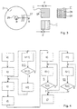
- Figure 3 diagrammatically illustrates a recording medium 21 in plan view, an optical grating 1 with a grating constant d, a second optical grating 1' with a grating constant d' and a two-dimensional optical grating 1''.
- the recording medium 21 is designed as a circular disc with a central hole 26.
- Spirally or concentrically arranged information tracks 27 are represented diagrammatically on a greatly enlarged scale for part of the recording medium 21.
- the line B-B indicates the section of the recording medium 21 that is illustrated in Figure 2.
- the spacing of the information tracks 27 from one another corresponds to the spacing of the grating lines 28 of the grating 1. This spacing corresponds to the grating constant d.
- the spacing of the information tracks 27 is so small that they appear virtually parallel in a small detail illuminated by the pencil 5 of rays.
- the grating lines 28 are therefore likewise arranged parallel.
- Grating 1' has a grating constant d' which is smaller than that of grating 1 and corresponds to a recording medium with a correspondingly smaller spacing of the information tracks.
- the grating 1'' is a two-dimensional grating, that is to say it has two groups of grating lines 28, 28' arranged at an angle, in this case at a right angle, relative to one another.
- Such a grating 1'' enables even tilting components whose influence becomes apparent perpendicularly to the lines 28, and cannot therefore be detected by a single grating 1, 1', to be made detectable without rotation of the grating.
- a two-dimensional grating 1'' can also be designed as a hologram; the structure represented in Figure 3 serves here principally for illustration purposes.
- gratings with arcuately curved lines which preferably have an average radius occurring in the case of a recording medium.
- the wavelength ⁇ and the numerical aperture NA are, inter alia, also optimized to the spacing of the information tracks 27 from one another and the width thereof, so that there is also a direct correlation between the spacing of the information tracks 27 and the suitable grating constant d.
- the grating is fixed to the disc turntable 17 or to the puck 18.
- the scanner 2 in order to carry out the compensation of tilting, the scanner 2 is moved radially inwards in such a way that the pencil 5 of rays detects the grating.
- the grating is preferably designed to be reflective, so that the detector 23 of the scanner 2 is used.
- FIG. 4 shows a flow chart of a method according to the invention.
- step a the optical grating 1 or the recording medium 21 is introduced into the beam path which follows the optical element, the focusing means 6 in the exemplary embodiment.
- step b the light source 4 is activated.
- step c) the focal point of the pencil 5 of rays is varied in such a way that it is located alternately on one side and on the other side of the grating plane 9 or of the information carrier plane 19. This movement is also maintained during the following steps.
- step d) sees the beginning of the detection of the intensity of the light coming from the grating 1 or from the recording medium 21 by means of the detector element 13 or 23.
- step e) sees the beginning of the measurement of the contrast between minima and maxima of the intensity, that is to say the beginning of the determination of the modulation amplitude A.
- step f) is composed of the sub-steps f01), in which the tilting of the optical element 6 is varied by means of the tilting device 7, and the step f02), in which a check is made to see whether the modulation amplitude A has reached a maximum value. If this is not the case, the step f01) is repeated. Otherwise, step f) is concluded and, in step g), the focal point variation begun in step c), the detection begun in step d) and the contrast determination begun in step e) are ended and the tilting set in step f) is maintained.
- This tilting is either maintained permanently, for example if the setting of the tilting involves that setting which is carried out during the production of the apparatus, or it is maintained until the next time that the compensation of tilting is carried out, if the said compensation involves an operation that is carried out more or less regularly.
- step b1 which consists of two sub-steps b11) and b12
- the grating 1 is oriented in the normal plane to the desired direction of the optical axis 8.
- step b11 the orientation is changed; in step b12), a check is made to see whether the changed orientation is correct. If this is not the case, step b11) is repeated, otherwise the method branches to the following step.
- a further additional method step b2) consists in the variation of the position of the grating 1 in the grating plane in a direction crossing the grating lines 28. This is effected by switching on the drive device 16 in the exemplary embodiment in accordance with Figure 1.
- the variation of the position of the grating 1 is expediently ended in step g). If a recording medium 21 is used as grating, it is appropriate in this case to cause the disc turntable 17 to rotate, as a result of which a customary eccentricity of the information tracks 27 relative to the axis of rotation of the recording medium 21 likewise ensures that the information tracks 27 are displaced, or oscillate, in the radial direction.
- step f1) the grating 1 is rotated about an axis lying parallel to the optical axis 8, and then in step f2) the tilting of the optical element 6 is varied perpendicularly to the tilting direction varied in step f) until the modulation amplitude A reaches a maximum.
- Steps f21) and f22) correspond to steps f01) and f02) except for the direction of the variation. If a two-dimensional grating 1'' is used, the rotation is effected in step f1) by an angle whose value lies between 0° and 90°. Step f2) then merely involves monitoring whether the tilting setting that has been found is already the optimum setting.
- the modulation amplitude A greatly depends on the tilting of the focusing means 6 or other optical elements situated in the beam path, with the result that, by maximizing the contrast, the tilting will be corrected to zero. Only the light source 4 and an actuator for varying the focal point have to be operationally available for this.
- the modulation amplitude A detected by the detector element 13, 23 greatly depends on the size of the focal point on the grating plane 9. The modulation amplitude A is maximized by changing the tilting of the focusing means 6.
- the direction of the tilting which is compensated for in this case is perpendicular to that of the grating lines 28 of the grating 1.
- the grating 1 is rotated in a second step or a two-dimensional grating 1'' is used from the outset.
Landscapes
- Physics & Mathematics (AREA)
- Optics & Photonics (AREA)
- Optical Recording Or Reproduction (AREA)
Applications Claiming Priority (2)
| Application Number | Priority Date | Filing Date | Title |
|---|---|---|---|
| DE19918801 | 1999-04-26 | ||
| DE19918801A DE19918801A1 (de) | 1999-04-26 | 1999-04-26 | Gerät zum Lesen oder Beschreiben optischer Aufzeichnungsträger |
Publications (1)
| Publication Number | Publication Date |
|---|---|
| EP1049083A1 true EP1049083A1 (de) | 2000-11-02 |
Family
ID=7905834
Family Applications (1)
| Application Number | Title | Priority Date | Filing Date |
|---|---|---|---|
| EP00108211A Withdrawn EP1049083A1 (de) | 1999-04-26 | 2000-04-14 | Gerät zum Lesen von und/oder Schreiben auf optischen Aufzeichnungsmedien |
Country Status (5)
| Country | Link |
|---|---|
| US (1) | US6678222B1 (de) |
| EP (1) | EP1049083A1 (de) |
| JP (1) | JP4345192B2 (de) |
| CN (1) | CN1137471C (de) |
| DE (1) | DE19918801A1 (de) |
Families Citing this family (5)
| Publication number | Priority date | Publication date | Assignee | Title |
|---|---|---|---|---|
| JP3674565B2 (ja) * | 2001-09-25 | 2005-07-20 | ティアック株式会社 | 光ディスク装置 |
| TWI229858B (en) * | 2002-11-29 | 2005-03-21 | Lite On It Corp | Adjustment system and method of optical disk drive |
| TWI227885B (en) * | 2002-12-24 | 2005-02-11 | Lite On It Corp | Adjustment system of compact disc player using screen for display and method thereof |
| EP2497258A4 (de) | 2009-11-06 | 2013-05-01 | Freescale Semiconductor Inc | Telefonkonferenzsystem, verfahren und computerprogrammprodukt |
| CN110060706B (zh) * | 2018-01-18 | 2021-03-19 | 青岛泰谷光电工程技术有限公司 | 一种全像信息读取装置及方法 |
Citations (5)
| Publication number | Priority date | Publication date | Assignee | Title |
|---|---|---|---|---|
| US5001690A (en) * | 1988-02-03 | 1991-03-19 | Yamaha Corporation | Tilt servo circuit for an optical disc playback device |
| DE4211213A1 (de) * | 1992-04-03 | 1993-10-07 | Thomson Brandt Gmbh | Regelung optischer Abtastsysteme, insbesondere in der Anlaufphase der Abspielgeräte |
| JPH08115528A (ja) * | 1994-10-17 | 1996-05-07 | Sanyo Electric Co Ltd | 光ヘッドのチルト制御方法及びその制御装置 |
| US5523989A (en) * | 1993-11-16 | 1996-06-04 | Matsushita Electric Industrial Co., Ltd. | Optical disk drive having functions of detecting disk tilt from difrraction pattern of track and compensating disk tilt with use of comatic lenses |
| EP0886266A2 (de) * | 1997-06-19 | 1998-12-23 | Sony Corporation | Optische Platte und optisches Plattenlaufwerk |
Family Cites Families (16)
| Publication number | Priority date | Publication date | Assignee | Title |
|---|---|---|---|---|
| JPS59186145A (ja) * | 1983-04-06 | 1984-10-22 | Sony Corp | 光学式デイスク・プレ−ヤ |
| DE68923833T2 (de) * | 1988-06-20 | 1996-06-13 | Mitsubishi Electric Corp | Optischer Kopf mit Kippkorrekturservomechanismus. |
| JP2866160B2 (ja) * | 1990-07-19 | 1999-03-08 | パイオニア株式会社 | 光学式ディスクプレーヤ |
| KR100254024B1 (ko) * | 1990-07-23 | 2000-06-01 | 가나이 쓰도무 | 반도체 장치의 제조 방법 |
| DE4028703A1 (de) * | 1990-09-10 | 1992-03-12 | Thomson Brandt Gmbh | Verfahren zum messen oder regeln des radial- und tangentialwinkels eines lichtstrahls |
| US5442615A (en) * | 1991-11-20 | 1995-08-15 | Sony Corporation | Optical plate for correcting comatic aberration |
| JP3350146B2 (ja) * | 1993-06-07 | 2002-11-25 | 株式会社リコー | 対物レンズ傾き調整装置 |
| JPH07140381A (ja) * | 1993-11-18 | 1995-06-02 | Sony Corp | コマ収差補正方法 |
| JP3176544B2 (ja) * | 1995-12-13 | 2001-06-18 | 株式会社日立製作所 | 光ディスク装置 |
| JPH1021578A (ja) * | 1996-07-04 | 1998-01-23 | Matsushita Electric Ind Co Ltd | 半導体レーザー装置の調整方法および調整装置 |
| JP3795143B2 (ja) * | 1996-07-31 | 2006-07-12 | シャープ株式会社 | 対物レンズ姿勢調整方法及び対物レンズ傾き検出装置並びに対物レンズ姿勢調整装置 |
| JP3211002B2 (ja) * | 1997-04-24 | 2001-09-25 | 富士通株式会社 | 光記録媒体、チルト検出器、光ディスク装置、チルト検出方法及びチルト補正方法 |
| JPH1118216A (ja) * | 1997-06-18 | 1999-01-22 | Tsuneo Sato | 絶縁配線配電盤及び裏配線用端子台 |
| JP3114661B2 (ja) * | 1997-07-15 | 2000-12-04 | ヤマハ株式会社 | 光ディスク装置のチルト制御装置 |
| JPH1153750A (ja) * | 1997-07-31 | 1999-02-26 | Hitachi Ltd | 傾き検出方法及び光ディスク装置 |
| EP1042749A1 (de) * | 1998-08-10 | 2000-10-11 | Koninklijke Philips Electronics N.V. | Vorrichtung zur aufzeichnung auf einen optischen datenträger |
-
1999
- 1999-04-26 DE DE19918801A patent/DE19918801A1/de not_active Withdrawn
-
2000
- 2000-04-14 EP EP00108211A patent/EP1049083A1/de not_active Withdrawn
- 2000-04-19 JP JP2000118045A patent/JP4345192B2/ja not_active Expired - Fee Related
- 2000-04-21 CN CNB001068679A patent/CN1137471C/zh not_active Expired - Fee Related
- 2000-04-26 US US09/560,880 patent/US6678222B1/en not_active Expired - Fee Related
Patent Citations (5)
| Publication number | Priority date | Publication date | Assignee | Title |
|---|---|---|---|---|
| US5001690A (en) * | 1988-02-03 | 1991-03-19 | Yamaha Corporation | Tilt servo circuit for an optical disc playback device |
| DE4211213A1 (de) * | 1992-04-03 | 1993-10-07 | Thomson Brandt Gmbh | Regelung optischer Abtastsysteme, insbesondere in der Anlaufphase der Abspielgeräte |
| US5523989A (en) * | 1993-11-16 | 1996-06-04 | Matsushita Electric Industrial Co., Ltd. | Optical disk drive having functions of detecting disk tilt from difrraction pattern of track and compensating disk tilt with use of comatic lenses |
| JPH08115528A (ja) * | 1994-10-17 | 1996-05-07 | Sanyo Electric Co Ltd | 光ヘッドのチルト制御方法及びその制御装置 |
| EP0886266A2 (de) * | 1997-06-19 | 1998-12-23 | Sony Corporation | Optische Platte und optisches Plattenlaufwerk |
Non-Patent Citations (1)
| Title |
|---|
| PATENT ABSTRACTS OF JAPAN vol. 1996, no. 09 30 September 1996 (1996-09-30) * |
Also Published As
| Publication number | Publication date |
|---|---|
| JP2000322753A (ja) | 2000-11-24 |
| CN1137471C (zh) | 2004-02-04 |
| CN1271930A (zh) | 2000-11-01 |
| DE19918801A1 (de) | 2000-11-02 |
| JP4345192B2 (ja) | 2009-10-14 |
| US6678222B1 (en) | 2004-01-13 |
Similar Documents
| Publication | Publication Date | Title |
|---|---|---|
| US5097464A (en) | Optical recording medium and optical recording/reproducing apparatus | |
| US7307769B2 (en) | Hologram recording medium, recording/reproducing method and recording/reproducing apparatus | |
| US5621717A (en) | Reading optical disks having substrates with diverse axial thicknesses | |
| US7453791B2 (en) | Optical recording medium having a plurality of guide tracks transfer regions | |
| JP4295636B2 (ja) | ホログラム記録方法 | |
| JPS60246026A (ja) | 光学的再生装置用のサ−ボ誤差減少装置 | |
| US6678222B1 (en) | Apparatus for reading from or writing to optical recording media having a tilting-compensation device | |
| CN102087867B (zh) | 光记录介质、光记录介质驱动装置及光记录介质驱动方法 | |
| JP4419200B2 (ja) | 種々の構造を有する光記録媒体への書き込み及び/又は読み出し装置 | |
| JP2850822B2 (ja) | レンズアクチュエータ | |
| US6577581B2 (en) | Variable recording layer disk image pickup device | |
| US7327662B2 (en) | Optical pickup and optical disk drive | |
| CA2580512C (en) | Optical disc and optical disc apparatus | |
| KR20120053971A (ko) | 홀로그래픽 복제 시스템 내 병렬 트랙을 가진 마스터 디스크를 위한 서보 시스템 | |
| US7274649B2 (en) | Holographic ROM system | |
| CN1312679C (zh) | 光拾取装置及其控制方法 | |
| KR100657693B1 (ko) | 홀로그래픽 롬 디스크의 서보 장치 | |
| KR100601286B1 (ko) | 홀로그래픽 롬 시스템의 기준광 각도 서보 장치 | |
| CN121438884A (zh) | 一种基于体存储光盘信号读出方法 | |
| JPH0944856A (ja) | 光ディスクドライブ装置 | |
| CN101317223A (zh) | 用复数个光点在光盘上读/写数据的系统和方法 | |
| JPH0464930A (ja) | 光ディスク装置のトラッキングエラー検出装置 | |
| HK1018117B (en) | Device for writing and/or reading optical recording medium of various designs | |
| JPH0845104A (ja) | 光ピックアップ装置 | |
| KR20060061647A (ko) | 홀로그래픽 롬 재생 시스템의 서보 장치 |
Legal Events
| Date | Code | Title | Description |
|---|---|---|---|
| PUAI | Public reference made under article 153(3) epc to a published international application that has entered the european phase |
Free format text: ORIGINAL CODE: 0009012 |
|
| AK | Designated contracting states |
Kind code of ref document: A1 Designated state(s): DE FR GB IT |
|
| AX | Request for extension of the european patent |
Free format text: AL;LT;LV;MK;RO;SI |
|
| 17P | Request for examination filed |
Effective date: 20010412 |
|
| AKX | Designation fees paid |
Free format text: DE FR GB IT |
|
| 17Q | First examination report despatched |
Effective date: 20071030 |
|
| RAP1 | Party data changed (applicant data changed or rights of an application transferred) |
Owner name: THOMSON LICENSING |
|
| RAP1 | Party data changed (applicant data changed or rights of an application transferred) |
Owner name: THOMSON LICENSING |
|
| STAA | Information on the status of an ep patent application or granted ep patent |
Free format text: STATUS: THE APPLICATION IS DEEMED TO BE WITHDRAWN |
|
| 18D | Application deemed to be withdrawn |
Effective date: 20100121 |