EP1049357A2 - Logement de réception possédant une couche isolante pour éléments chauffants radiants et procédé de fabrication de rainures dans la couche isolante - Google Patents
Logement de réception possédant une couche isolante pour éléments chauffants radiants et procédé de fabrication de rainures dans la couche isolante Download PDFInfo
- Publication number
- EP1049357A2 EP1049357A2 EP00108510A EP00108510A EP1049357A2 EP 1049357 A2 EP1049357 A2 EP 1049357A2 EP 00108510 A EP00108510 A EP 00108510A EP 00108510 A EP00108510 A EP 00108510A EP 1049357 A2 EP1049357 A2 EP 1049357A2
- Authority
- EP
- European Patent Office
- Prior art keywords
- channels
- insulating layer
- receiving tray
- tray according
- holes
- Prior art date
- Legal status (The legal status is an assumption and is not a legal conclusion. Google has not performed a legal analysis and makes no representation as to the accuracy of the status listed.)
- Withdrawn
Links
- 238000010438 heat treatment Methods 0.000 title claims description 20
- 238000004519 manufacturing process Methods 0.000 title claims description 7
- 238000002955 isolation Methods 0.000 title 2
- 238000000034 method Methods 0.000 claims description 10
- 239000000463 material Substances 0.000 claims description 9
- VYPSYNLAJGMNEJ-UHFFFAOYSA-N Silicium dioxide Chemical compound O=[Si]=O VYPSYNLAJGMNEJ-UHFFFAOYSA-N 0.000 claims description 8
- 239000000377 silicon dioxide Substances 0.000 claims description 4
- 239000002184 metal Substances 0.000 claims description 2
- 230000006835 compression Effects 0.000 claims 3
- 238000007906 compression Methods 0.000 claims 3
- 239000012774 insulation material Substances 0.000 abstract description 3
- 230000001627 detrimental effect Effects 0.000 abstract 1
- 238000009413 insulation Methods 0.000 description 7
- 239000002241 glass-ceramic Substances 0.000 description 4
- 239000000835 fiber Substances 0.000 description 2
- 239000003605 opacifier Substances 0.000 description 2
- 239000011148 porous material Substances 0.000 description 2
- 230000015572 biosynthetic process Effects 0.000 description 1
- 239000000919 ceramic Substances 0.000 description 1
- 239000011888 foil Substances 0.000 description 1
- 239000011810 insulating material Substances 0.000 description 1
- 230000002093 peripheral effect Effects 0.000 description 1
- 230000035699 permeability Effects 0.000 description 1
- 238000003825 pressing Methods 0.000 description 1
- 238000000926 separation method Methods 0.000 description 1
Images
Classifications
-
- H—ELECTRICITY
- H05—ELECTRIC TECHNIQUES NOT OTHERWISE PROVIDED FOR
- H05B—ELECTRIC HEATING; ELECTRIC LIGHT SOURCES NOT OTHERWISE PROVIDED FOR; CIRCUIT ARRANGEMENTS FOR ELECTRIC LIGHT SOURCES, IN GENERAL
- H05B3/00—Ohmic-resistance heating
- H05B3/68—Heating arrangements specially adapted for cooking plates or analogous hot-plates
- H05B3/74—Non-metallic plates, e.g. vitroceramic, ceramic or glassceramic hobs, also including power or control circuits
- H05B3/748—Resistive heating elements, i.e. heating elements exposed to the air, e.g. coil wire heater
Definitions
- the invention relates to a receptacle for at least a radiant heating element of a radiant heater, especially a stove, on the bottom of the Receiving cup an insulating layer is arranged.
- the invention further relates to a method for Production of channels in such an insulating layer.
- Such a receptacle is from DE 27 44 079 A1 and DE 28 06 367 A1.
- the insulation layer consists mainly of pressed microporous Silica with opacifiers and fibers. The Insulating layer is in the mentioned writings described.
- a holder DE 27 44 079 A1
- a connection bushing DE 28 06 367 A1
- the highly disperse silica of the insulating layer takes off Moisture.
- the Radiant heating element evaporates the moisture in the Inside the insulating layer.
- the resulting Vapor bubbles can cause the insulation layer to flake off lead what is undesirable.
- EP 0 618 399 B1 describes a microporous one Thermal insulation molded body described in which to increase the Gas permeability channel pores are provided. These are made by pushing in pins. Becomes a such thermal insulation molded body in a conventional Receptacle inserted, then the channel pores are at the bottom closed. The one leaving the insulation layer upwards Steam hits the radiant heating element and one usually covering the top of the holder Glass ceramic plate. Both are undesirable.
- the object of the invention is to provide a tray Propose the type mentioned, in which the gas or Steam discharge from the insulating layer and the Receiving tray is improved. It is also the task of Invention, a simple method of making a to specify such an insulating layer.
- Another advantage of the method described is in that the channels are created in the same operation be in which the insulating layer is pressed. Compared to the prior art, in which the Insulating layer is pressed and then through the channels Needling is produced is described Procedure saved one operation.
- the channels on the Radiant heating element associated surface of the Insulation layer closed. This ensures that the Turn on the radiant heater, i.e. at the Heat up, at most little gas or steam on the Radiant heating element and a holding tray on top final glass ceramic plate meets.
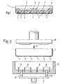
- a receptacle 1 is made of sheet metal Pressed thermal insulation material and forms a Insulating layer 2.
- a suitable as thermal insulation material Material based on disperse silica, if necessary with fibers and opacifiers. Such material is known from EP 0 618 399 B1 and DE 28 06 367 A1.
- the insulating layer 2 borders directly on the bottom 1 ' the tray 1. Outside the center of the Bottom 1 'consist of several channels in the insulating layer 2 3. A channel can also be in the center of the bottom 1 ' be arranged.
- the depth of channels 3 is complete approximately perpendicular to the floor 1 '.
- the bottom 1 ' has open Holes 4 into which the channels 3 open.
- the insulating layer 2 is in the center area 5 and Edge area 6 thicker than in intermediate areas 7.
- the Edge area 6 and the central area 5 serve the Support of a not shown Radiant heating element, for example a heating foil.
- a not shown Radiant heating element for example a heating foil.
- the insulating layer 2 is not.
- the holder 1 with radiant heating element is in the usual way to arrange a gas ceramic plate, not shown.
- this can Radiant heating element as a spiral Heating coil in a known manner directly on the Insulating layer 2 may be arranged.
- the channels 3 do not go through the insulating layer 2 through it. They are on the radiant heating element associated surface of the insulating layer 2 closed.
- the channels 3 are essentially the same in FIG. 1 spaced. However, it is also possible to channel 3 in thinner intermediate area 5 less from each other spaced than in the thicker areas, i.e. in the Center area 5 and in the peripheral area 6. This is the Steam discharge in the thinner, stronger than the thicker Areas compressed intermediate area 7 supported.
- the cross-sectional area of the channels is, for example, approximately 0 mm 2 to 30 mm 2 .
- the cross-sectional area in the zone adjoining the base 1 ' is slightly smaller than the cross-sectional area of the holes 4.
- the specified lower limit 0mm 2 relates to a conical shape (cf. FIGS. 3a, 3b), in which the cross-sectional area is 0 and above downwards, towards the receiving tray 1, expanded.
- the channels 3 are roughened on the inside.
- the inner surface of the channels 3 can be angular, star-shaped or wavy cross-section enlarge.
- the channels 3 are essentially cylindrical. However, they can also be designed how this corresponds to the geometries according to FIG. 3.
- the insulating layer 2 pressed into the receiving shell 1 has a tendency to moisture from the environment to record. Is the cradle 1 under the Glass ceramic plate mounted and will Radiant heating element switched on, then the evaporates Moisture inside the insulating layer 2 quickly. The forming gas bubbles enter the channels 3 and pull out through the open holes 4 without flaking occurs on the insulating layer. So that is the moisture essentially from the insulating layer 2 removed without the radiant heater and the Apply glass ceramic plate. Should the Insulating layer 2 moisture again in later operation record, then this is always when switching on the Radiant heating element through channels 3 and the open ones Holes 4 derived.
- the channels 3 in the insulating layer 2 at the holes 4 can be produced according to Figure 2 as follows:
- the receptacle 1 prefabricated with the holes 4 is used in a tool 8, which corresponds to the Receptacle 1 is cup-shaped.
- arbors 9 are arranged which when inserting the Receiving tray 1 in the direction of arrow P through holes 4 of the bottom 1 'of the receiving shell 1 protrude.
- the in the Receiving tray 1 depth of the mandrels 9 is so dimensioned that they the desired depth extension of the Channels 3 corresponds.
- Each hole 4 does not have to have a mandrel 9 be assigned; however, each mandrel 9 must have a hole 4 be assigned.
- the method described is not limited to that the insulating layer 2 directly into the receptacle 1 is pressed. It is also possible to use the insulating layer 2 into a shape corresponding to the receiving shell 1 press in and thereby create the channels. The so prefabricated by pressing and channel formation Insulating layer can then be at another work station into the receptacle 1 prepared with the holes 4 be used, with appropriate alignment it is achieved that the channels 3 at the open holes 4th flow out.
- the mandrels 9 can have different geometries, whereby not all mandrels 9 have the same geometry have to.
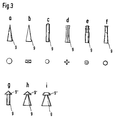
- Figure 3 are different geometries for the Arbors 9 shown.
- the respective mandrel is according to FIG. 3a 9 conical with circular cylindrical cross section designed.
- the mandrel 9 is pyramid-shaped designed with a rectangular cross-section.
- the mandrel 9 cylindrical with a roughened tip Surface.
- the mandrel 9 has one at the bottom larger cross section than being in the middle, being upper cross section in its dimensions between the Dimensions of the middle cross section and the bottom Cross-section lies.
- the cross-section is star or cruciform.
- the mandrel 9 is stepped cylindrical an upper frustoconical approach.
- Figure 3f is a lower part of the mandrel 9 frustoconical, wherein this is followed by a cylindrical section, which is followed by a wavy star-shaped end section at the top.
- the channels 3 can as described above by a Variety of rotationally symmetrical mandrels 9 created become. However, it is also possible to use channels 3 slit-shaped or groove-shaped, the Longitudinal extension of the slots or grooves parallel to the The bottom of the receptacle runs. The perpendicular to this Cross-sectional profile of the slots or grooves can then in Figure 3 cross-sectional profile shown with the thorns correspond. The longitudinal extension of the slots or Grooves is then preferably larger than that in the Insulating layer 2 projecting depth of the slots or grooves. The slots or grooves can be made that instead of the rotationally symmetrical mandrels Corresponding webs are provided on the tool 8.
- the holes 4 are elongated when the insulating layer 2 directly into the receiving shell 1 is pressed. If the insulating layer 2 is first in a shape with simultaneous production of the channels 3 pressed in and only then into the receiving tray 1 inserted, then holes 4 of the receiving shell are sufficient not over the entire length of the slots or Must extend grooves. It is sufficient if the holes 4 so are distributed that from the slots or grooves Vapor bubbles can escape through the holes.
- the slots or grooves facilitate the desired one Steam or gas leak because the channels are very form large inner surface.
- For the creation of Slitting or creasing on tool 8 is a number of Bridges necessary, which is smaller than the number of otherwise necessary mandrels 9.
Landscapes
- Chemical & Material Sciences (AREA)
- Engineering & Computer Science (AREA)
- Ceramic Engineering (AREA)
- Cookers (AREA)
- Steam Or Hot-Water Central Heating Systems (AREA)
- Resistance Heating (AREA)
Applications Claiming Priority (2)
| Application Number | Priority Date | Filing Date | Title |
|---|---|---|---|
| DE19919784 | 1999-04-30 | ||
| DE1999119784 DE19919784A1 (de) | 1999-04-30 | 1999-04-30 | Aufnahmeschale mit einer Isolierschicht für Strahlungsheizelemente und Verfahren zur Herstellung von Kanälen in der Isolierschicht |
Publications (2)
| Publication Number | Publication Date |
|---|---|
| EP1049357A2 true EP1049357A2 (fr) | 2000-11-02 |
| EP1049357A3 EP1049357A3 (fr) | 2001-12-12 |
Family
ID=7906470
Family Applications (1)
| Application Number | Title | Priority Date | Filing Date |
|---|---|---|---|
| EP00108510A Withdrawn EP1049357A3 (fr) | 1999-04-30 | 2000-04-19 | Logement de réception possédant une couche isolante pour éléments chauffants radiants et procédé de fabrication de rainures dans la couche isolante |
Country Status (2)
| Country | Link |
|---|---|
| EP (1) | EP1049357A3 (fr) |
| DE (1) | DE19919784A1 (fr) |
Cited By (1)
| Publication number | Priority date | Publication date | Assignee | Title |
|---|---|---|---|---|
| EP2073601A3 (fr) * | 2007-12-21 | 2009-08-26 | Eika, S.Coop | Chauffage radiant électrique |
Families Citing this family (1)
| Publication number | Priority date | Publication date | Assignee | Title |
|---|---|---|---|---|
| DE10134520A1 (de) * | 2001-07-16 | 2003-01-30 | Bsh Bosch Siemens Hausgeraete | Vorrichtung mit zumindest einer einen Garraum begrenzenden Wand |
Citations (3)
| Publication number | Priority date | Publication date | Assignee | Title |
|---|---|---|---|---|
| DE2744079A1 (de) | 1976-09-30 | 1978-04-06 | Micropore International Ltd | Elektrische kochplatte mit glatter oberflaeche |
| DE2806367A1 (de) | 1977-02-10 | 1978-08-17 | Micropore International Ltd | Thermisches, isolierendes material |
| EP0618399B1 (fr) | 1993-03-31 | 1996-11-13 | Wacker-Chemie GmbH | Corps calorifuge microporeux |
Family Cites Families (2)
| Publication number | Priority date | Publication date | Assignee | Title |
|---|---|---|---|---|
| DE3810586A1 (de) * | 1988-03-29 | 1989-10-12 | Ego Elektro Blanc & Fischer | Beheizung fuer elektrische kochgeraete |
| GB2323507B (en) * | 1997-03-21 | 2000-11-29 | Ceramaspeed Ltd | Electric heater unit and method of manufacture |
-
1999
- 1999-04-30 DE DE1999119784 patent/DE19919784A1/de not_active Withdrawn
-
2000
- 2000-04-19 EP EP00108510A patent/EP1049357A3/fr not_active Withdrawn
Patent Citations (3)
| Publication number | Priority date | Publication date | Assignee | Title |
|---|---|---|---|---|
| DE2744079A1 (de) | 1976-09-30 | 1978-04-06 | Micropore International Ltd | Elektrische kochplatte mit glatter oberflaeche |
| DE2806367A1 (de) | 1977-02-10 | 1978-08-17 | Micropore International Ltd | Thermisches, isolierendes material |
| EP0618399B1 (fr) | 1993-03-31 | 1996-11-13 | Wacker-Chemie GmbH | Corps calorifuge microporeux |
Cited By (1)
| Publication number | Priority date | Publication date | Assignee | Title |
|---|---|---|---|---|
| EP2073601A3 (fr) * | 2007-12-21 | 2009-08-26 | Eika, S.Coop | Chauffage radiant électrique |
Also Published As
| Publication number | Publication date |
|---|---|
| DE19919784A1 (de) | 2000-11-02 |
| EP1049357A3 (fr) | 2001-12-12 |
Similar Documents
| Publication | Publication Date | Title |
|---|---|---|
| DE602004001569T2 (de) | Formverfahren durch Warmprägen von komplexen Blechen aus Verbundstoffen und Vorrichtung zu dessen Durchführung | |
| DE3942266C2 (de) | PTC-Heizkörper | |
| EP0210575B1 (fr) | Corps de chauffe électrique à radiation pour réchauffer des plaques chauffantes ainsi que procédé et dispositif pour sa fabrication | |
| DE2950302A1 (de) | Elektrischer strahlheizkoerper sowie verfahren und vorrichtung zu seiner herstellung | |
| EP0243575B1 (fr) | Echangeur de chaleur et/ou de matière et procédé de fabrication des échangeurs de chaleur et/ou de matière | |
| EP0750444B1 (fr) | Corps de chauffe rayonnant et son procédé de fabrication | |
| EP0633327A1 (fr) | Procédé pour le revêtement d'utensiles de ménage et de cuisine | |
| EP4434720A1 (fr) | Moule pour la fabrication de pièces moulées et procédé de fabrication de pièces moulées à l'aide d'un moule | |
| DE102008042992B4 (de) | Speichereinrichtung, insbesondere Heißwasseraufbereiter | |
| DE3233181C2 (de) | Aus keramischen Fasern vakuumgeformte, elektrische, freistrahlende Widerstands-Heizvorrichtung für Industrieöfen und Verfahren zu deren Herstellung. | |
| EP1049357A2 (fr) | Logement de réception possédant une couche isolante pour éléments chauffants radiants et procédé de fabrication de rainures dans la couche isolante | |
| AT402735B (de) | Gasspülstein mit gerichteter porosität | |
| DE102019120854B4 (de) | Herstellungsverfahren und -vorrichtung sowie gemäß dem Herstellungsverfahren hergestellter Faserguss-Becher | |
| EP1165272A1 (fr) | Procede de production de joints homocinetiques | |
| DE4202569C2 (de) | Formwerkzeuge zum Pressen von Dämmschalen | |
| DE4303396A1 (de) | Preßformen von perforierten Gegenständen | |
| EP1002187B1 (fr) | Systeme d'echappement de gaz | |
| EP1801282B1 (fr) | Fer à repasser à vapeur et procédé d'obtention un fer à repasser à vapeur | |
| DE19543463A1 (de) | Kältemittelsammler | |
| DE4331724A1 (de) | Ein Trägeraufbau für ein Heizelement für eine Herdplatte | |
| DE29704371U1 (de) | Elektrisches Heizelement mit profiliertem Außenmantel | |
| DE29500253U1 (de) | Vorrichtung zur Herstellung eines Rohrs aus Schüttgut | |
| DE3735179A1 (de) | Strahlungs-heizeinheit sowie verfahren zur herstellung einer strahlungs-heizeinheit | |
| EP4237119B1 (fr) | Procédé et dispositif de production d'un dispositif de filtrage | |
| DE60123200T2 (de) | Vorgeformtes Schalldämmelement und Verfahren zur Herstellung desselben |
Legal Events
| Date | Code | Title | Description |
|---|---|---|---|
| PUAI | Public reference made under article 153(3) epc to a published international application that has entered the european phase |
Free format text: ORIGINAL CODE: 0009012 |
|
| AK | Designated contracting states |
Kind code of ref document: A2 Designated state(s): AT BE CH CY DE DK ES FI FR GB GR IE IT LI LU MC NL PT SE Kind code of ref document: A2 Designated state(s): DE ES GB IT |
|
| AX | Request for extension of the european patent |
Free format text: AL;LT;LV;MK;RO;SI |
|
| PUAL | Search report despatched |
Free format text: ORIGINAL CODE: 0009013 |
|
| AK | Designated contracting states |
Kind code of ref document: A3 Designated state(s): AT BE CH CY DE DK ES FI FR GB GR IE IT LI LU MC NL PT SE |
|
| AX | Request for extension of the european patent |
Free format text: AL;LT;LV;MK;RO;SI |
|
| AKX | Designation fees paid |
Free format text: DE ES GB IT |
|
| STAA | Information on the status of an ep patent application or granted ep patent |
Free format text: STATUS: THE APPLICATION IS DEEMED TO BE WITHDRAWN |
|
| 18D | Application deemed to be withdrawn |
Effective date: 20020613 |