EP1049604B1 - Montants a positions alternantes et leur utilisation - Google Patents
Montants a positions alternantes et leur utilisation Download PDFInfo
- Publication number
- EP1049604B1 EP1049604B1 EP99900858A EP99900858A EP1049604B1 EP 1049604 B1 EP1049604 B1 EP 1049604B1 EP 99900858 A EP99900858 A EP 99900858A EP 99900858 A EP99900858 A EP 99900858A EP 1049604 B1 EP1049604 B1 EP 1049604B1
- Authority
- EP
- European Patent Office
- Prior art keywords
- change
- platform
- supports
- over
- vehicle
- Prior art date
- Legal status (The legal status is an assumption and is not a legal conclusion. Google has not performed a legal analysis and makes no representation as to the accuracy of the status listed.)
- Expired - Lifetime
Links
Images


Classifications
-
- B—PERFORMING OPERATIONS; TRANSPORTING
- B60—VEHICLES IN GENERAL
- B60P—VEHICLES ADAPTED FOR LOAD TRANSPORTATION OR TO TRANSPORT, TO CARRY, OR TO COMPRISE SPECIAL LOADS OR OBJECTS
- B60P1/00—Vehicles predominantly for transporting loads and modified to facilitate loading, consolidating the load, or unloading
- B60P1/64—Vehicles predominantly for transporting loads and modified to facilitate loading, consolidating the load, or unloading the load supporting or containing element being readily removable
- B60P1/6418—Vehicles predominantly for transporting loads and modified to facilitate loading, consolidating the load, or unloading the load supporting or containing element being readily removable the load-transporting element being a container or similar
- B60P1/6427—Vehicles predominantly for transporting loads and modified to facilitate loading, consolidating the load, or unloading the load supporting or containing element being readily removable the load-transporting element being a container or similar the load-transporting element being shifted horizontally in a fore and aft direction, combined or not with a vertical displacement
-
- B—PERFORMING OPERATIONS; TRANSPORTING
- B60—VEHICLES IN GENERAL
- B60P—VEHICLES ADAPTED FOR LOAD TRANSPORTATION OR TO TRANSPORT, TO CARRY, OR TO COMPRISE SPECIAL LOADS OR OBJECTS
- B60P1/00—Vehicles predominantly for transporting loads and modified to facilitate loading, consolidating the load, or unloading
- B60P1/64—Vehicles predominantly for transporting loads and modified to facilitate loading, consolidating the load, or unloading the load supporting or containing element being readily removable
- B60P1/6409—Vehicles predominantly for transporting loads and modified to facilitate loading, consolidating the load, or unloading the load supporting or containing element being readily removable details, accessories, auxiliary devices
Definitions
- the invention relates to an interchangeable support for high or low positions of Transport goods on platforms, in particular for a transport structure, the Interchangeable support swiveling via an articulated axis, with the platform and one Traction device is connected or connectable.
- the invention further relates to the Use of the change support.
- the invention is based on an exchange system, as is described in WO97 / 13654 is described.
- WO97 / 13654 was based on the task of changing from one Set up a vehicle in the standing room function without special aids such as Through cranes or forklifts at any location, not just at the home terminal to be able to carry out a person.
- the Setting up a lifting and lowering device with four distributed bearings for synchronous lifting and lowering of the structure.
- one Collecting funnel / centering cone combination for catching and pushing the body with its own weight and defined placement on the chassis.
- As a lift off Lowering device serves four hydraulic cylinders mounted on the chassis, which are operated by a control from a hydraulic pump.
- Taking off and lowering the container or platform or any one Transport structure is essentially vertical, relative to the chassis and not to the floor.
- the container as an example, is delivered to the desired location driven a motor vehicle, the swap body with a small-stroke Lifting and lowering device raised about 20 to 30 cm from the chassis and then insert the floor supports in a vertical position.
- the four cylinders will be retracted again, the container at the same time standing up on the meter-long floor supports is parked.
- the vehicle can then under the Move the supports away without a container.
- Appropriate Swap bodies have already proven themselves in practical use. With a Time expenditure in the range of minutes can e.g. a moving container for household items at the place of loading.
- the invention has now been given the task of loading goods, whether on platforms such as Transport superstructures, interchangeable platforms or containers without external lifting gear in relation to be able to bring the floor in either high or low positions.
- platforms such as Transport superstructures, interchangeable platforms or containers without external lifting gear
- the elevated position for assembly / disassembly on or from one Vehicle and the low position for a shorter or longer stay at one location be usable.
- the change from a stationary vehicle to be able to combine in a simple way.
- the solution according to the invention is characterized in that the change support has a pull lever, which projects upward above the joint axis, as a force arm and a load arm to power arm in relation to the effective length ratio changeable lever forms, whereby for overcoming the greatest traction situations the load arm is relatively shortened.
- the invention allows a number of configurations.
- the Swap supports are preferred as rocker arm supports with one or more Knee joints and the joint axes particularly preferably parallel to the Vehicle axles trained. Winches are preferred as pivoting aids or motorized means that are fixed to the vehicle. Are the Joint axes parallel to the vehicle axes, so with tensile forces in Driving direction of the motor vehicle applied the required pivoting forces become.
- Each knee lever support advantageously has a kink foot at least two legs connected by a joint, the inner Knee angle of the load arm through articulated stops to an angle greater than 90 ° is limited. Furthermore, it is also possible that each floor support two or has several articulation points, each knee angle of the load arm through Joint stops is limited.
- a simple change from a stationary / vehicle can according to WO97 / 13654. Against all or part Lowering the transported goods to the floor according to the new solution carried out.
- the swap supports can be used in the idealized case Roll rails are formed, which also on the articulation point have the extension arm extended.
- the design as Roll-off rail has the great advantage that the forces in the course of the lowering and Change the lifting motion smoothly and load the drive system more evenly.
- the kink foot or joint solution has the advantage that the floor supports on the shortest possible dimensions are collapsible, which is very important in the vehicle sector is.
- the joints are reversed in the direction of the tensile stress designed to be collapsible.
- the forces from the pivoting aids can in various ways or with Habegger hand winches, lever tensioners etc. be transmitted.
- the pivoting movement can be done by pushing or pulling over mechanical, electrical or hydraulic pivoting aids are carried out.
- the container as a whole is parallel to the
- the floor supports must be lowered and raised on both sides of the floor Structure connected by a parallel train, for the coordinated movement of all Floor supports.
- the pivoting aids are called motor or hydraulic Tools trained and firmly anchored to the motor vehicle. It's very much about that advantageous if a displacement lock is arranged on the motor vehicle, the can be clamped between floor supports and motor vehicle. The required This counteracts traction for lifting and lowering the body, so that neither the motor vehicle nor the transport structure can move through the Can move pivoting forces horizontally.
- the shift lock can be used as Movable rod formed and / or combined with a vehicle support in Be put into action.
- the Pivoting aids have at least in part a pull rope, which is advantageously performed at the rear of the vehicle. If the motor vehicle is also not absolutely in alignment with the structure, can be easily with the rope laterally deviating forces are absorbed. So that even in extreme situations Chassis of the motor vehicle is not too heavily loaded, the Pivotal tools and the vehicle support a common point of intervention on Have vehicle. Furthermore, the floor support can be used as a spring e.g. as an air spring be trained so that at least the last movement piece when lowering the Building on the floor can be used as energy storage and later lifting is facilitated.
- An optimal solution results if both sides of the Motor vehicle preferred protection against displacement and the pivoting aids are arranged in the longitudinal center axis of the vehicle. According to another Design can be within a body or container, if necessary even several intermediate decks are arranged, which are equally over the new exchangeable props can be raised and lowered.
- the new solution goes in two directions and affects two basic manipulations that to date, especially together, have never been resolved appropriately. It is this complete lowering of a container to the ground without crane help, as well as loading of a transport superstructure, as it were on a green meadow, even here without crane help or stacking vehicles. It is an experience fact that a single person is having simple aids that can move several hundred kg. Once the weight is one Special tonnage is required. This still applies reinforced if it is not just a weight of maybe 1 to 3 tons or acts more, but if the object to be moved is also large. It is recognized that placing a load is still easy when on the vehicle even hoists are available. Mere lifting and lowering is also one easy manipulation.
- the situation is different when one is somewhere on the floor Structure parked on supports, e.g. 2 to 4 tons or much more weight and a few meters in length must be placed on a chassis with millimeter precision.
- the purpose of the new solution is also that the transport mass at Settling with their own weight captured and pushed and into an exact defined position can be placed on the chassis. As for charging that full load weight is used, the weight itself no longer matters.
- the process can therefore be performed by a single person, without human effort can be carried out without any problems, especially if the lifting device is motorized is driven and controllable.
- the quick change has to be shown as yet becomes a multiple meaning. It can be set up quickly by one Vehicle can be changed to a standing instrument.
- the type of Structure or a first e.g. fuller by a second empty quickly change. Use in light vehicles is just as possible as in heavy transport vehicles, including the lowering of the floor.
- the new solution is also characterized by a modular design.
- a first one Module is as an interchangeable platform with storage locations and with a lifting and Lowering device designed.
- a second module is used as a cross member or Cross member group trained. This can be as a kit at the bottom of one Structure to be attached.
- the two modules, the swap platform module and the Extension module can now be manufactured inexpensively in larger series and the individual manufacturers such as Vehicle manufacturers or container manufacturers for the fixed installation can be supplied by this. It has been recognized that at Utilization of the dead space previously available for the spring deflection of the chassis Especially with light vehicles, many problems of the prior art at the same time are solvable.
- the interchangeable platform can be manufactured in a lightweight construction and only slightly reduces the payload.
- the swap platform is special advantageous for a vehicle trailer, but can also directly on the motor vehicle be grown yourself.
- the swap platform is used as a support platform for the construction formed, with a small-stroke lifting and lowering device firmly on the Interchangeable platform is arranged.
- the interchangeable platform particularly preferably has at least two longitudinal and cross members with a longitudinal and Cross adjustment range to adapt to a wide range of chassis.
- On one Additional middle longitudinal spars of the swap platform can e.g. the aggregate for the motor drive, the control lines and the control elements for the Lifting and lowering device can be hung.
- the longitudinal and cross members can be designed as plug-in profiles, the longitudinal beams a number Have recesses for insertion into any width Regarding the longitudinal beams. This solution allows for wide, within one Maximum and a minimum to set any measure. The any protruding end can be cut off by the vehicle manufacturer.
- the structure has at least two permanently attached Support cross beams on which floor supports are optional, be it as stiff in itself Supports or as rocker arm supports or articulated feet are attachable for one quick change of the body as a stationary or as part of the vehicle and that Lowering to the floor.
- Support cross beams of the construction each have two, preferably flat support surfaces and a middle one Centering funnel, with the support surfaces each a lifting device and Centering devices are each assigned a centering pin, which on the Interchangeable platform are fixed.
- each lifting device preferably as a lifting device hydraulically actuated cylinders. It will be the two outer ones Support cross members each assigned a central centering device, that is, for the whole a structure preferably two centering devices.
- the new solution also allows to attach to the cross and longitudinal beams side panel parts, the Length of the cross and longitudinal cross members according to the specific chassis adjusted or shortened.
- any loading area or a structure optionally supported firmly on the floor or with a preferably be connected under the body sliding chassis. there the platform is lifted and arranged on the chassis Lowering device placed on the chassis or lifted off the chassis and can then be transported by a light motor vehicle.
- the structure or the platform with any structure gets the according to the new solution Function of a payload and must comply with the relevant traffic regulations.
- the interchangeable platform is built as lightly as possible, otherwise the free payload weight is restricted.
- the inventor has also recognized that so far large Areas of goods handling were not sufficiently taken into account. They are the Handling bulky, light general cargo and especially the time factor. Even the largest volumes can be transported quickly over long distances. are the goods at the destination, but the problems only begin because the takeover of large Volume can often no longer be planned in advance. The vehicle must then take too long stand still at the destination, so that a vehicle becomes a very expensive stationary.
- the chassis can be moved by a small truck from e.g. 3.5 or 7 tons or a light motor vehicle like delivery van, powerful jeeps etc. are moved from place to place. This can also be done Motor vehicle itself can be designed according to the invention.
- the loading area can placed on the floor using simple supports according to WO97 / 13654 or with be connected to a chassis.
- the chassis can be fixed on the floor Drive under the supported platform.
- the chassis itself has a small stroke Lifting and lowering device on, and puts the driver in the position without further aids (such as a crane, forklift, etc.) the respective change (stationary vehicle) fast and in one-man operation, that is, simply and without one person to carry out special danger, since the lifting and lowering device only around a stroke of about 30 to 40 cm, i.e. adjusted by the length of one foot got to.
- the lifting and lowering device has the sole function in normal operation changing the platform from standing to moving vehicle and vice versa. That is why compared to the known transshipment facilities such as cranes, forklifts, etc. less expensive and is an integral part of the chassis.
- a motor lifting and Lowering device engages over bearings and is preferred for synchronous Lifting or lowering the bearing points.
- Four lifting and Lowering devices are distributed over the container base area and point Bearing points at which controllable lifting elements such as pneumatic cylinders, Attack hydraulic cylinders, air spring cushions, spindle motors or threaded spindles.
- controllable lifting elements such as pneumatic cylinders, Attack hydraulic cylinders, air spring cushions, spindle motors or threaded spindles.
- the lifting and lowering device can with a motor or by Hand powered scissors or even a support mast with a winch be equipped.
- the bearing points are advantageously located in the outer Quarter of the container arranged and designed as a cross member, the Bearings are each arranged in the outer end areas of the cross member.
- the Bearing points are preferably formed on the cross beams at which the Floor supports can be mounted or inserted via horizontal support arms. Very It is useful if one in the middle of the two cross members Centering funnel is arranged to catch a arranged on the chassis Centering pin, or for pushing and defined placement of the container the chassis.
- the chassis can be designed as a two-axle trailer, with two support axes on which hoists are arranged, preferably with each two hydraulic cylinders and one in the middle of each bearing axis Centering device, with the two support axes in the two outer quarters of the container are arranged. But it is also possible to have the trailer as one or two or to build three-axle vehicles. Both the platform are particularly preferred how the supports are designed symmetrically so that both directions of pull are identical are usable.
- the container For handling that is as universal as possible, it is also proposed that on the ceiling of the container preferably in two transverse planes, which the storage locations or Include bearing axles, crane hooks and bearing surfaces between the bearing points and a distance for fork stack interventions are arranged.
- the so designed Containers can also be transported in the manner known per se by rail or large trucks can be transported or reloaded.
- Between the container and the Chassis is a mechanically or hydraulically operated, preferably as Carabiner locking device arranged, which preferably attacks on the centering funnels.
- the container often has to be in very tight spaces Space should be placed on the nozzle Arrange maneuvering rollers in such a way that they can be used or lowered if necessary are.
- the container can only be moved into the best possible position with the towing vehicle become.
- the exact placement e.g. can also turn up to 90 ° from Hand made using the maneuvering rollers.
- This is a big advantage with very tight Space conditions, such as especially on construction sites or exhibitions or at Moving furniture in urban conditions is almost always the case.
- the surprising one The advantage is that a company e.g. no more 15 light or heavy trucks as before, but only a few vehicles or towing vehicles who must be able to hold a three to four ton trailer pull, further e.g. 15, 30 or more inexpensive bodies. Because the cost of that Loading area with body or corresponding container only a fraction of one Make motor vehicle, these can be very inexpensive at the destination, up to complete emptying.
- the structure can be designed as a barrack, which is supported for the standing time on preferably height-adjustable support legs and for the change to a next construction site by means of a chassis or a light motor vehicle is restrained.
- the structure is adaptable and will according to a further advantageous embodiment, designed as a container, the used as a transport vessel between dissimilar places and e.g.
- the parking height of the transport structure is adjustable. This also allows the loading area to be placed in an optimal position, and if necessary adjust the height of each support to the terrain, or one or more Bring platforms into a horizontal position.
- the invention also enables that one or more platforms directly on a loading area of a means of transport or is designed to be placed on the floor in such a way that e.g. for long distances General cargo e.g. can be transported by rail car, where the reloading means Crane hook or forklift takes place. It is also possible that the structure as Exhibition container is designed such that it is used for a trade fair stand or
- Sales stand needed light parts transported and platform with construction as Trade fair stand or part of a trade fair stand or sales stand is used.
- the new solution allows many other configurations, be it for heavy or light goods.
- the usable working area of the collecting funnel and the support plates is about the same size.
- the maneuvering accuracy of a vehicle is around 20 to 50 cm. Accordingly, it is proposed the diameter or the Dimension the side dimensions of the support plates and collecting funnel.
- On somewhat trained driver of a vehicle is able to drive the vehicle with a Park deviation of 10 to 25 cm in a given field. Many things For this reason, the floor supports are not used unnecessarily far apart.
- the required area or side dimensions of a standing instrument should be as small as to be possible.
- too large a projection has an unfavorable effect on the vigorous stress on the structure.
- the collecting funnel is not allowed to build too high and should not protrude into the loading area. From a given Starting from the base area, the height of the funnel increases the more pointed it is Angle is. The angle of more than 90 ° is preferred. About 120 ° represents one optimal compromise for the movement as well as the height Plates preferably form together with the lower edges of the Collecting funnel a common support level. This means that the structure can be as empty containers can be parked somewhere without supports or one above the other stacked or transported by rail or truck.
- the bearings are advantageously formed on two hollow profile cross members, in which the Supports can be plugged in.
- On the ceiling of the container are in two transverse levels, which include the bearing points, crane hooks arranged, Furthermore, there can be contact surfaces for forklift interventions between the support points to be ordered.
- the Platform and the chassis a mechanically or hydraulically operated Fuse arranged, which attack the centering funnels.
- the exploitation of special cross planes with the cross beams has the great advantage that the essential forces without loading the body structure directly onto the chassis or caught on the floor. The structure can be built more easily.
- the invention further relates to the use of the device for what to the claims 13-18.
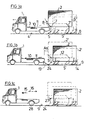
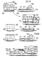
- FIGS. 1a to 1c Show motor vehicle 1 with chassis 4 and a container 2.
- the Motor vehicle has an interchangeable platform 3, e.g. in WO97 / 13654 is described. It is used for the corresponding configurations as well as variations referred to the entire content of the WO.
- container 2 can be any structure, depending on the intended use or current use.
- the structure can e.g. a dock leveler with or without Roof structure. It is essential that the Quick change from vehicle to stationary is also possible. But it is also possible the new solution independently of a collecting funnel / centering cone combination use.
- FIGS. 1 to 6 there is only one side of the container 2 shown.
- FIG. 7 shows a position in which a change from one vehicle to one A standing instrument according to WO97 / 13654 has already taken place.
- Container 2 stands up Exchange supports 5, 5 ', in total on four floor supports, and are therefore located in a high altitude. There is an intention to display the container for a long time Leaving high, would be the use of simple support legs recommend according to WO97 / 13654, i.e. simple, straight and vertical Support legs.
- WO97 / 13654 i.e. simple, straight and vertical Support legs.
- FIG. 1b the motor vehicle 1 is at a somewhat greater distance
- Container 2 has been driven.
- pivoting aids 10 on the interchangeable platform 3 arranged which e.g. can be designed as hydraulic cylinders, from which a traction cable 11 can be connected to the change supports 5.
- Figure 1b shows the Container 2 (with solid lines) in a middle lowered position, whereby can be seen the container is always in a parallel position during the arched movement Ground remains. The highest or lowest position is accordingly dash-dotted indicated (container 2 ', 2 ").
- the change supports 5, 5' are with a parallel train 12 connected, so that the pivoting movement of the floor supports is forced is coordinated.
- a shift lock 13 is arranged.
- the Locking device 13 can with lighter containers from a thin rod exist, which on one side of the vehicle or the interchangeable platform is stated that it is secured to the vehicle even when not in use and for the Use against the two nearest interchangeable supports is lockable.
- Prefers short feet 14 are attached to the container 2, on which the The structure is in the lowest position. The feet 14 can also be used as spring feet be designed so that the last section of the lowering via the deflection intercepted and when lifting as energy storage easier lifting.
- the feet 14 can also be used as Rollers are formed around this, especially in the case of lighter containers to give a slight possibility of displacement.
- Figure 1c is drawn with Lines of body 2 completely drained onto floor 9. The vehicle 1 is again free for other uses, as indicated by arrow 15. The arrow 16 shows the reverse situation. The vehicle 1 drives to the container 2, around which Reload container 2.
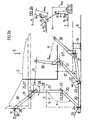
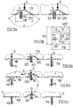
- FIG. 2a shows an interchangeable support 5 via the arcuate movement of the Containers 2 in three different positions, on the left in an upright position, on the right in Partially or completely lowered picture, labeled 5 * and 5 **.
- the Exchange support consists of a lower leg 20 and an upper leg 21 which are connected via a joint 22. Both legs 20, 21 can be in one Be brought to the knee. However, this is limited by stops 23, 23 '. so that a certain obtuse angle ⁇ no longer reduces the angle can be. The angle ⁇ is always greater than 90 ° but less under load than 180 °.
- the lower leg has a stop 24, which is the bottom 9 first touched.
- the upper leg 21 is pivotable on the body or container 2 a pivot 25 articulated.
- the two legs can thus around the pivot 25 are pivoted according to arrow 26.
- the axis of rotation 27 is the pivot pin 25 As shown in Figure 1c, parallel to the axes 28 of the vehicle 1, so that the Vehicle movement or the movement of the pull rope and the floor supports in the on the same level.
- the pivot 25 is in each position by a dimension X opposite the base 24 in the direction of the container center of gravity S. This has to Consequence that the container 2 in the high position on the floor supports 5 according to arrow 28 wants to fall off. The floor supports 5 must therefore on an uncontrolled Pivoting movement are prevented. On the one hand, this is done by fixing a pull arm 39 with a fixation 29 on the container 2.
- the pull arm 39 is in the Clockwise around the pivot pin 25, but only up to that shown Location, which is limited by a stop 31. There is a on the pull arm 39 Rope hook 32 to which the pull rope 11 can be fastened.
- the lowering movement now takes place in that the interchangeable support 5 extends around the support point 24 in a clockwise direction emotional.
- the angle ⁇ remains unchanged in the first lowering phase.
- the forces are by the pull rope 11 on the one hand and the base 24 of the interchangeable support intercepted.
- the base 24 is preferably as indicated by the radius R, rounded. 5 * shows the situation in which the first lowering phase is completed.
- the lower leg 21 lies completely on the floor 9.
- the further lowering is now carried out by rotating the upper leg 21 by the joint 22.
- the lowering movement can continue until that too Upper leg 21 rests completely on the floor 9, or as shown in the example until the container is supported on the feet 14. As long as the container is 2 on the feet 14, the change supports are not needed.
- the Exchange supports can be designed so that they are removable and can be stored collapsible in the vehicle or in the container.
- the leg configuration shown has the advantage that the lowering or Lifting movement can be done with relatively small tensile forces.
- FIGS. 2b and 2c show two dispositions corresponding to FIG. 2a during the lowering or lifting movement with the effective lever lengths.
- a low position is shown in FIG. 2b, which at the same time is very unfavorable with regard to a required leverage.
- the entire weight is moved around the pivot point D1.
- the result is a longer power arm KA1 in relation to the load arm LA1, the weight of the goods to be transported being indicated by G.
- the required pulling force Z 1 is relatively small due to the effective lever law.
- a change has already taken place in FIG. 2c, insofar as the movement now takes place around the pivot point D2.
- the cargo has already been lifted.
- this is not disadvantageous since the required movement force Z2 is only a fraction of the position according to FIG. 2b, which represents the maximum of the required lifting force.
- the lengths L 1, L 2 and L 3 are related as lever lengths in accordance with the lever laws, as indicated in FIG. 3.
- Figure 4 shows analogously the coordinated movement of the change supports 5 and 5 'for an intermediate deck in a container.
- Figures 4 and 8 show the corresponding with a platform 20x use possibility.
- Figures 5a, 5b and 5c show a further embodiment.
- the Transporting an entire container is a function.
- goods e.g. are transported on pallets, each pallet weighing e.g. 100 to Can have 300 kg, i.e. weights that cannot be lifted by a person without aids are manageable.
- the planned container concept basically sees loading and unloading the container from a starting point to a destination.
- the Intermediate unloading of individual loads is possible, but it is comparatively complex, since the whole container always has to be handled for heavy pieces must be drained to the floor if tools are not available stand.
- the container be it on the side or a lowerable platform 30 is arranged at the rear, which is connected via a pull rope 31 can be lowered.
- the pull rope 31 can be operated using a hand crank 32 or directly via the Pull rope 11 are operated.
- the platform 30 can via a rotary arm 33 on the one hand on a joint 34 of a support 36 and on the other hand on a joint 35 on the Platform 30 is attached. The moves from the horizontal position (thick lines) Platform held over the pivot points 34 and 35 and the pull rope 31 down, respectively. vice versa when lifting.
- FIG. 5b shows the change according to the invention the entire container, Figure 5c, the further possibility in which the platform 30 as Driving ramp can be used.
- FIG. 6 shows the design of a floor support 5 as a rolling rail or roll bar 40.
- FIG. 7 shows a further embodiment of the floor support 5 with many articulation points 50 to 55.
- a crossbar 60 is schematically shown, to which one or two displacement locks 13 can engage (FIG. 3).
- the anti-displacement device preferably acts on the stops 24.
- FIG. 8 shows the use of floor supports for lowering a platform, instead of the configuration according to FIG. 5a.
- FIG. 9a Another possibility is shown in FIG. 9a.
- the floor supports can be attached at the back or front and lifting by means of the truck's hook pull.
- Figures 9b, 9c and 9d show the situation of an interchangeable platform with a platform 120 which is mounted on a chassis, including an enlarged one System.
- a double-acting cylinder 140 is used on both sides Carabiner lock operated.
- a corresponding clamp wedge 142 engages in the Incline of the respective centering funnel 113 and secures the connection from the Platform 120 and the chassis 107. It is also possible as Additional security e.g. attach a chain lock 143.
- the clamping part safety has the great advantage that enormous forces are exerted by the hydraulics applied and in many cases the container is centered with millimeter precision Position is slidable. This allows further securing in the form of bolts or wedges to be attached by hand in the periphery of the swap platform.
- Figure 9b shows how the locking mechanism engages on both sides, forwards and backwards.
- the figure 9c is an enlargement of a locking side.
- the interaction is important of all contacting elements: the many support points through damping Intermediate layers 124, but in particular the double wedge action of the centering cone 112 inside the collecting funnel 113 and the clamping wedge 142 on the outside of the Einfangtrichters.
- the control and locking functions SV are from one Control box 160 operated, which preferably with the electrical system of the vehicle connected is.
- the lifting and lowering device hydraulic cylinders which are connected by a central hydraulic unit 161 with the Media are supplied. All valves and the switching on and off are done via the control box 160.
- FIGS. 10a to 10c there is an interchangeable support as an articulated foot or a rocker arm support shown in different positions.
- Figure 10a is from the side of the Transport structure seen from the inside.
- Figure 10a is the operational or Operating position.
- FIG. 10c shows the floor support as a package folded so that the bent feet at the smallest possible location when not in use e.g. can be supplied under the transport structure or on the vehicle.
- the Interchangeable support for lighter bodies with a payload of only a few tons determined then the three basic elements can be made in light metal, so that handling is made easier.
- the change supports can e.g. in the collapsed state also directly secured to the transport structure Position are fixed.
- the interchangeable support 5 is extended Position, which is either the starting point for mounting on the Transport structure can be, or vice versa, for disassembly.
- Position which is either the starting point for mounting on the Transport structure can be, or vice versa, for disassembly.
- the pull arm 39 and the lower leg 20 clockwise or in Counterclockwise pivoted as indicated by arrows 70 and 71.
- FIG. 10a additionally shows an articulated axis 72 on the transport structure self-assembled e.g. in a hollow profile 132 ( Figure 15).
- the joint axis too can according to the support legs 103 (according to Figures 12) on the transport structure quickly assembled or disassembled, or if necessary in the assembled state on the Transport setup remain in a secure position.
- the floor support 103 ( Figure 11a) are more for a longer duration in the case of a standing instrument, the rocker arm supports, however for the change from a high position to a low position and if the high position only lasts briefly.
- the hinge axis 72 has an extension 73 as Turning device in the assembled state, and a strong mounting shaft 74 to insert into the corresponding guide of the transport structure.
- a certain position in the high position can via a bolt 29 (as a fixation) and if necessary, be secured with an additional spring. So that the Transport setup remain in a high position for a certain time.
- the upper leg 21 is further inwardly in the assembled state by a spacer 75 and outwards through a split pin or locking pin 76 on the pivot pin 25 held against a sliding movement.
- a bore 77 is in the upper leg 21 attached, in which the pivot pin 25 is mounted with sufficient play. Also the Floor supports are in this way with the concept of modular structures designed. The use of the individual modules can be tailored to the specific needs establish.
- the bolt 29 acts as an anti-rotation device together with one Safety bolt 29 '. This means that the transport structure can be secured in a high position are, at least during the period of a reload or change of position (Standing toy vehicle).
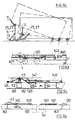
- FIGS. 11a, 11b and 11c Here is in the figure 11a as a body and a camper in the figure 11b a simple Shown container.
- Figure 11c shows a caravan as a trailer, which is at Or can be used as a stand-alone train on interchangeable supports.
- a light vehicle 100 that is shown as a two-axle system, e.g. be a vehicle type known under the Names Mercedes Sprinter, VWLT35, Ford Transit, IVECO etc.
- On the left is a Structure shown as an interchangeable container 102, which supports 103 on the floor 104 is supported.
- An arrow 106 indicates that the vehicle 101 in the Is with its rear part of its chassis 107 among the Swap body 102 to drive.
- the swap container 102 is then on the Chassis mounted, as will be shown in more detail below.
- arrow 108 is symbolizes the fully assembled unit as a ready-to-drive vehicle.
- Figures 11b and 11c show two further possible uses, namely transport with the Vehicle itself or with a trailer, and Figure 11b the transport with both Transporting with a trailer 109 has a great advantage in that it can be pulled with a passenger car or a jeep, within the scope of the permissible loading weights.
- FIGs 12a, 12b and 12c are three different positions from the beginning the lowering movement of the body 102 until it is placed on the chassis shown. 12a is also the end of the lifting movement of the Containers from the support on the ground over the supports 103.
- the chassis has an interchangeable platform 110 at the top, which is an intermediate link between the actual chassis and the elements via which the change is carried out becomes. These elements consist of a lifting and lowering device 111 and a centering cone 112.
- the centering cone 112 forms together with a Capture funnel 113 a capture funnel / centering cone combination 114.
- the lift-off and lowering device 111 consists of several, preferably vie Hydraulic cylinders 115, which via a piston rod 116 and a Piston rod head 117, each support the structure 102 via a support plate 118
- the structure has a platform 119, on the underside of which a cross member 120 is attached to which both the collecting funnel 113 and the two Sliding plates / support plates 118 are firmly connected.
- the cross member 120 can be used as Be formed hollow profile, in which a horizontal at the two outer ends Carrier 121 is mountable or insertable, which is part of the vertical supports 103 The supports 103 are lifted from the floor by a small dimension X in FIG.
- Centering cone 112 is in its simplest form a massive round iron body with a conical one Top and rigidly connected to the chassis or the swap platform.
- the Centering cone 112 can also be mechanically movable, for example. as moveable Be formed piston, and take on other functions.
- the main functions the centering cone 112 is a rejection of the collecting funnel 113, a centering of the collecting funnel and ultimately securing the structure in the centered position.
- the arrow 122 in Figure 12b indicates the vertical movement of the structure from above down at.
- the arrow 123 indicates the horizontal sliding movement caused by the Deflection movement between centering cone 113 and the corresponding inclined surface 125 'of the collecting funnel is formed ( Figure 14).
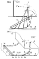
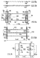
- FIGS. 13a and 13b and 14a to 14c A further important aspect of the new invention can be seen in FIGS. 13a and 13b and 14a to 14c, namely the size of the sliding plate and of the collecting funnel. It is assumed that the greatest width of the chassis WB and the greatest width CB of the container are approximately the same. In contrast, the clear width between the supports Stw is larger by a dimension B1 and B2 (FIG. 12a). B1 + B2 is the game that the driver has to park the chassis under the body 12. The width LB of the bearing plates 118 and the width TB of the collecting funnel are approximately the same and approximately the same size as B1 and B2 together. In practice, this measure is between 120 and 50 cm.
- each parking position within the clear width Stw between the supports leads to the same result, the precise placement on the chassis.
- the same problem occurs in the transverse direction of the vehicle, as in the longitudinal direction of the vehicle, as shown in FIG. 3.
- the funnel has four sliding surfaces 125, 125 ', 125 ", 125'".
- Each of the inclined sliding surfaces 125 causes the centering cone to come into the center position Z (FIG. 14c).
- the angle a is preferably chosen to be greater than 90 ° optimally in the range of approximately 120 °. With G the weight of the container is indicated.
- the capture funnels can also have a shape other than a simple pyramid, e.g. rounded insertion surfaces.
- the catch funnel has the actual function of catching the body in the centered, safe position for driving on the road.
- a lubricant G L can be attached to the slide plate or to the bearing point of the piston rod 1 b or to the piston head 116 '.
- FIGS. 15a, 15b, 15c and 15d and 16 show a container module Cross member group and the systematic arrangement of the elements discussed to each other.
- the optimal disposition is that the two collecting funnels 113 in the longitudinal plane of symmetry 130 of the container can be arranged.
- For the Wobble and pushing forces an optimum, respectively. similar or same conditions in all four directions (sideways and lengthways).
- the arrangement is recommended to act on the container in lightweight construction of the two support plates 118 like the collecting funnels 113 in the back and front in one common transverse plane 131 respectively. 131 '.
- the cross member 120 from a central hollow profile 132 and two assemble side profiles 133. Both cross beams 120 and 120 'are connected with two longitudinal connections 134, 134 'and form one Cross member assembly or add-on module 135 with an interchangeable platform or the bottom, possibly wooden floor, of a container can be screwed.
- the expressions front and rear refer to the direction of travel, then have at the top no meaning if the whole structure is designed symmetrically.
- the cross beams can be used as a standard group and the longitudinal connections 134 on each Vehicle type or size can be adjusted. However, it is optimal for both Directions a standard measure.
- FIG. 15d shows a single swap platform module. Fictitious the location of the bearing points 150 and the centering points 151 is shown Centering points 151 are located in the longitudinal plane of symmetry 130. Front and rear are located in a transverse axis 131 'and 131 two bearing points 150 and a centering point 151 in the middle.
- the motorized lifting and Lowering device engages over bearings and is for synchronous lifting or Lowering the bearings.
- the container base preferably has four over the Distributed storage locations on the container base, at which motor drive means such as pneumatic cylinders, hydraulic cylinders, air spring cushions, spindle motors or Attack threaded spindles preferably controllable synchronously.
- motor drive means such as pneumatic cylinders, hydraulic cylinders, air spring cushions, spindle motors or Attack threaded spindles preferably controllable synchronously.
- the lifting and Lowering device can be operated with a motonsch or by hand Scissors to be equipped.
- the essential basic elements of the interchangeable platform module are two longitudinal beams 162, 162 ', a central beam 165 and two strong ones Crossbeams 163, 163 'which are designed as plug-in profiles with recess 164 are. This allows assembly with different lengths and Width dimensions.
- the longitudinal beams can be fitted to the side members of the Vehicle set and rigidly connected.
- the length L var and the width B var can thus be adapted to any type of vehicle.
- FIG. 16 shows a simple configuration of a cross member construction.
- Figures 17a and 17b show an interesting use of the bend feet according to the invention, for loading and / or unloading, in particular e.g. for lowering and lifting heavy loads e.g. on a plateau, a loading ramp, a transport frame or a pallet or a loading area or if necessary via appropriate trusses on the load itself.
- a heavy one Load unloaded from a means of transport and then through a building Gate openings through, moved to a level lower by a few steps become.
- the horizontal push usually works without problems e.g. on rolls, by Push or pull. Lowering or lifting is a big problem if crane equipment cannot be used in the building, due to a lack of height.
- the heavy weight G e.g. be a transformer station. This is the first step at ground level unloaded. At the same time, a platform with four articulated feet is built inside the building assembled, with the front feet hitting the stairs to intercept the horizontal displacement. The means of transport will be used against one horizontal displacement secured, symbolically indicated with a brake pad. The Lowering takes place as described several times above.
- the reverse Order results when lifting or loading loads. This problem can already exist for loads of 100 kg or more, e.g. Boiler.
- the big advantage is that the vertical lifting function in one Train function is converted. It is crucial in all cases that the kinky feet in any way via trusses etc. on the load itself or on the loading area are connectable and grip cleanly. The traction can in many cases applied by an electric winch or a hand winch or a lifting unit become.
Landscapes
- Engineering & Computer Science (AREA)
- Transportation (AREA)
- Mechanical Engineering (AREA)
- Forklifts And Lifting Vehicles (AREA)
- Loading Or Unloading Of Vehicles (AREA)
- Handcart (AREA)
Claims (14)
- Montant à positions alternantes permettant de soulever et d'abaisser des marchandises transportées sur des plates-formes (30, 120), en particulier pour une structure de transport (2, 2'), moyennant quoi le montant à positions alternantes (5, 5') peut basculer autour d'un axe d'articulation (25, 27), et est relié ou peut être raccordé à la plate-forme (30, 120) ainsi qu'à un dispositif de traction (10, 11),
caractérisé en ce que
le montant à positions alternantes (5, 5') comprend un levier de traction (39) comme bras d'entraínement (KA), s'écartant vers le haut par l'intermédiaire de l'axe d'articulation (25, 27) et un levier pouvant passer du bras de force (LA) au bras d'entraínement (KA) en fonction du rapport de longueur efficace. - Montant à positions alternantes selon la revendication 1,
caractérisé en ce que
le bras de puissance (LA) comprend au moins une ou plusieurs genouillère(s) (22) et forme un montant de levier coudé. - Montant à positions alternantes selon la revendication 1 ou 2,
caractérisé en ce que
quatre montants à positions alternantes (5, 5') sont disposés de manière à pouvoir basculer et se déplacer dans le même sens sur la zone inférieure de la plate-forme (30, 120) ou d'une structure de transport (2, 2') et peuvent être reliés aux moyens de basculement (10, 11, 12), de telle sorte que les plates-formes (30) ou la structure de transport (2, 2') puisse(puissent) être abaissée(s) d'un côté sur le sol (9) ou dans une position inférieure par l'intermédiaire de déplacements de levier correspondants des montants à positions alternantes (5, 5'), et être amenée(s) d'un autre côté à nouveau dans une position supérieure. - Montant à positions alternantes selon l'une des revendications 1 à 3,
caractérisé en ce qu'un angle coudé (α) intérieur du bras de puissance (LA) pour la position de fonctionnement peut être limité par des butées d'articulation (23, 23') présentant un angle supérieur à 90°. - Montant à positions alternantes selon la revendication 1,
caractérisé en ce qu'au moins deux montants à positions alternantes (5, 5') sont réalisés sous forme de rails de roulement (40), lesquels comprennent un levier de traction (39) se prolongeant au-delà de l'axe d'articulation (25, 27) sur la structure. - Montant à positions alternantes selon l'une des revendications 1 à 5,
caractérisé en ce que
respectivement deux montants à positions alternantes (5, 5') sont reliés sur chaque côté de la structure (2, 2') par une traction parallèle (12), afin de coordonner le déplacement de tous les montants à queue de lion, moyennant quoi le basculement se fait de préférence par un mouvement de poussée ou de traction par l'intermédiaire de moyens de basculement (10, 11, 12) mécaniques, électriques ou hydrauliques. - Montant à positions alternantes selon l'une des revendications 1 à 6,
caractérisé en ce que
le fait de faire passer la plate-forme (30) ou la structure de transport (2, 2') d'une position supérieure à une position inférieure ou inversement peut être réalisé en créant une tension entre la plate-forme (30) et un véhicule à moteur, moyennant quoi la tension se fait de préférence d'un côté par l'intermédiaire d'un dispositif de traction parallèle (12) agissant entre le véhicule à moteur (1) et l'extrémité extérieure du bras d'entraínement (KA), et d'un autre côté par un frein de déplacement (13), agissant des deux côtés entre le véhicule à moteur (1) et le bras de puissance (LA) du montant à positions alternantes (5, 5'). - Montant à positions alternantes selon la revendication 7,
caractérisé en ce que
le dispositif de traction (12) comprend au moins comme élément un câble de traction (11), lequel est guidé de préférence sur l'extrémité arrière du véhicule, et est associé de manière particulièrement préférée à un montant de véhicule (103) vertical, pouvant être réglé en longueur. - Montant à positions alternantes selon la revendication 1,
caractérisé en ce qu'il comprend des branches reliées par l'intermédiaire de deux axes d'articulation (22, 27) ou plus, moyennant quoi la branche (20, 21) comprenant un bras de traction (39) relié de manière articulée peut être rabattue sous forme de paquet lorsqu'elle n'est pas utilisée, contrairement à sa position tendue lorsqu'elle est utilisée activement. - Montant à positions alternantes selon l'une des revendications 1 à 9,
caractérisé en ce qu'il comprend au moins un ou plusieurs dispositif(s) d'arrêt, permettant de fixer (29) la plate-forme (30, 120) ou la structure de transport (2, 2') dans une position supérieure ou intermédiaire. - Utilisation du montant à positions alternantes selon la revendication 1 pour le passage rapide de marchandises transportées, comprenant un support de transport pour le passage entre les positions supérieures et inférieures,
caractérisée en ce quea) le transfert de la forme mobile à la forme immobile d'une plate-forme (30, 120) ou d'une structure de transport (102) se fait dans une position supérieure par un dispositif de levage et d'abaissement (111) agissant verticalement sur une faible élévation etb) par l'intermédiaire d'un basculement des montants à positions alternantes (5, 5'), il se fait d'un côté un abaissement sur le sol (9) ou dans une position inférieure et d'un autre côté, à nouveau une élévation dans une position supérieure. - Utilisation du montant à positions alternantes selon la revendication 11,
caractérisée en ce que
les montants à positions alternantes (5, 5') sont réalisées en faisant partie d'une construction modulaire, laquelle comprend au moins une passerelle à positions alternantes (110) pouvant être reliée au châssis du véhicule (107), sur laquelle sont montés les dispositifs de levage et d'abaissement (111), ainsi que le cône central (112), moyennant quoi la passerelle à positions alternantes (110) est disposée sur le châssis de véhicule (107) de préférence dans la zone du trajet de compression du ressort du châssis de véhicule (107,), moyennant quoi les montants à positions alternantes (5, 5') peuvent être utilisés de préférence en option, à la place de béquilles (103) verticales. - Utilisation du montant à positions alternantes (5, 5') selon la revendication 1, pour le chargement et/ou le déchargement, en particulier pour l'abaissement et le levage de charges (G) lourdes, moyennant quoi quatre montants à positions alternantes (5, 5') sont fixés de manière rotative par des axes articulations sur une plate-forme (30, 120), une rampe de chargement, un châssis de transport ou une plaque, et les charges peuvent être supportées à court terme dans une position supérieure sans nécessiter de forces extérieures par l'intermédiaire d'un frein de rotation.
- Utilisation des montants à positions alternantes selon la revendication 1, pour des carrosseries à plate-forme de camion ou des bennes alternantes ou des containeurs, ou pour des entreponts dans des structures ou des containeurs pour le levage avec un cric d'une remorque de camping ou d'une structure de camping-car.
Applications Claiming Priority (5)
| Application Number | Priority Date | Filing Date | Title |
|---|---|---|---|
| CH17998 | 1998-01-26 | ||
| CH17998 | 1998-01-26 | ||
| DE19820074A DE19820074C2 (de) | 1998-01-26 | 1998-05-06 | Bodenstütze für das Wechseln zwischen Hoch- bzw. Tieflagen von Transportgütern sowie Verwendung derselben |
| DE19820074 | 1998-05-06 | ||
| PCT/CH1999/000034 WO1999037501A1 (fr) | 1998-01-26 | 1999-01-26 | Montants a positions alternantes et leur utilisation |
Publications (2)
| Publication Number | Publication Date |
|---|---|
| EP1049604A1 EP1049604A1 (fr) | 2000-11-08 |
| EP1049604B1 true EP1049604B1 (fr) | 2004-03-17 |
Family
ID=25683785
Family Applications (1)
| Application Number | Title | Priority Date | Filing Date |
|---|---|---|---|
| EP99900858A Expired - Lifetime EP1049604B1 (fr) | 1998-01-26 | 1999-01-26 | Montants a positions alternantes et leur utilisation |
Country Status (4)
| Country | Link |
|---|---|
| US (1) | US6582176B1 (fr) |
| EP (1) | EP1049604B1 (fr) |
| AT (1) | ATE261831T1 (fr) |
| WO (1) | WO1999037501A1 (fr) |
Families Citing this family (2)
| Publication number | Priority date | Publication date | Assignee | Title |
|---|---|---|---|---|
| US8998557B2 (en) * | 2013-03-13 | 2015-04-07 | David Douglas Dieziger | Pickup truck loading system |
| DE102022101937A1 (de) * | 2022-01-27 | 2023-07-27 | Wacker Neuson Linz Gmbh | Baufahrzeug |
Family Cites Families (16)
| Publication number | Priority date | Publication date | Assignee | Title |
|---|---|---|---|---|
| US1049210A (en) * | 1912-03-23 | 1912-12-31 | Leslie Percival Cole Jr | Automatic truck-body lifter. |
| DE456468C (de) * | 1926-07-10 | 1928-02-23 | Walther Plock | Vorrichtung zum Be- und Entladen von Kraftfahrzeugen mittels eines auf das Fahrzeug zu senkenden Ladegestells |
| US2656942A (en) * | 1950-10-02 | 1953-10-27 | George V Helms | Retractable gear for portable freight units |
| US3266774A (en) * | 1964-08-03 | 1966-08-16 | Clark Equipment Co | Lifting mechanism |
| GB1168902A (en) * | 1967-02-07 | 1969-10-29 | Dobson Ltd W E & F | Improvements in or relating to Transportable Load-Carrying Appliances |
| GB1189341A (en) * | 1967-04-08 | 1970-04-22 | Dobson Ltd W E & F | Improvements in or relating to Transportable Load-Carrying Appliances |
| FR1573174A (fr) | 1968-04-10 | 1969-07-04 | ||
| US3520433A (en) * | 1968-08-23 | 1970-07-14 | Miller Trailers Inc | Truck-tractor chassis and detachable container chassis |
| DE1927497A1 (de) * | 1969-05-30 | 1970-12-23 | Hans Schuster | Ladeplattform |
| DE2239718A1 (de) * | 1972-08-12 | 1974-02-14 | Fahr Ag Maschf | Transportfahrzeug |
| US3868088A (en) * | 1974-02-15 | 1975-02-25 | Charles F Reeves | Apparatus for mounting camper bodies and the like |
| DE2420603C2 (de) * | 1974-04-27 | 1984-04-12 | BS-LKW-Spezialaufbauten GmbH, 3300 Braunschweig | Mechanisches Wechselsystem für abstellbare Aufbauten von Lastkraftwagen, Anhängern oder Sattelaufliegern |
| JPS5728695Y2 (fr) | 1979-05-01 | 1982-06-23 | ||
| CA1190917A (fr) * | 1982-08-03 | 1985-07-23 | David N. Whitehouse | Plate-forme amovible pour chassis de camion ou de remorque |
| DE4240125C2 (de) * | 1992-11-30 | 1997-08-28 | Werdau Fahrzeugwerk | Hydraulische Absetzeinrichtung für Wechselaufbauten |
| JPH11513339A (ja) | 1995-10-09 | 1999-11-16 | エーリッヒ ミュラー | 軽量の物品を搬送するための方法および装置 |
-
1999
- 1999-01-26 AT AT99900858T patent/ATE261831T1/de not_active IP Right Cessation
- 1999-01-26 US US09/601,030 patent/US6582176B1/en not_active Expired - Fee Related
- 1999-01-26 WO PCT/CH1999/000034 patent/WO1999037501A1/fr not_active Ceased
- 1999-01-26 EP EP99900858A patent/EP1049604B1/fr not_active Expired - Lifetime
Also Published As
| Publication number | Publication date |
|---|---|
| EP1049604A1 (fr) | 2000-11-08 |
| ATE261831T1 (de) | 2004-04-15 |
| WO1999037501A1 (fr) | 1999-07-29 |
| US6582176B1 (en) | 2003-06-24 |
Similar Documents
| Publication | Publication Date | Title |
|---|---|---|
| EP2479132A2 (fr) | Grue de chargement et véhicule doté d'une grue de chargement | |
| DE8911634U1 (de) | In Teilen transportierbares Vergnügungsgerät für Jahrmärkte od.dgl., insbesondere Riesenrad | |
| DE102012019248A1 (de) | Turmdrehkran | |
| EP0025557B1 (fr) | Véhicule de transport avec systèmes hydrauliques de soulèvement pour superstructures mobiles | |
| DE102014002497B4 (de) | Verfahren und Einrichtung zum Koppeln eines ersten und eines zweiten begehbaren Containers | |
| EP2571663B1 (fr) | Procédé et systeme de production pour la fabrication d'éléments préfabriqués en matériaux à liants minéraux | |
| DE19820074C2 (de) | Bodenstütze für das Wechseln zwischen Hoch- bzw. Tieflagen von Transportgütern sowie Verwendung derselben | |
| EP1049604B1 (fr) | Montants a positions alternantes et leur utilisation | |
| EP1907310B1 (fr) | Remorque pour un vehicule automobile | |
| DE4036701A1 (de) | Bodengestuetzter klein-drehkran | |
| WO1998050252A1 (fr) | Vehicule et dispositif pour le transport de conteneurs | |
| DE4021948C2 (de) | Transportable Mischanlage für Baustellen | |
| EP0850157B1 (fr) | Procede et dispositif pour transporter des articles legers | |
| DE19543632C2 (de) | Einrichtung zum Transport von Stückgütern durch ein leichtes Fahrzeug | |
| EP0883513B1 (fr) | Dispositif de transbordement rapide, son agencement et son utilisation pour le transport de marchandises legeres | |
| DE29500135U1 (de) | Portalkran | |
| CH423589A (de) | Leicht transportable, ohne Kran aufstellbare Betonieranlage | |
| EP1688300B1 (fr) | Dispositif pour charger et décharger une plate-forme | |
| WO2005056432A1 (fr) | Palonnier | |
| DE3840649C1 (en) | Collapsible, portal-crane-like assembly device | |
| CH415314A (de) | Kraftfahrzeug zum Transport von schweren Lasten | |
| EP3246200A1 (fr) | Dispositif de chargement | |
| DE2927430A1 (de) | Fahrzeug, insbesondere lkw mit einem fuer den transport von stahlbetonraumzellen, insbesondere von fertiggaragen eingerichteten aufbau | |
| DE2848387A1 (de) | Fahrzeug zum transportieren und aufstellen von fertiggaragen | |
| CH309375A (de) | Maschine zum Heben und Transportieren von Lasten. |
Legal Events
| Date | Code | Title | Description |
|---|---|---|---|
| PUAI | Public reference made under article 153(3) epc to a published international application that has entered the european phase |
Free format text: ORIGINAL CODE: 0009012 |
|
| 17P | Request for examination filed |
Effective date: 20000715 |
|
| AK | Designated contracting states |
Kind code of ref document: A1 Designated state(s): AT BE CH DE DK ES FR GB IT LI NL SE |
|
| 17Q | First examination report despatched |
Effective date: 20030120 |
|
| GRAP | Despatch of communication of intention to grant a patent |
Free format text: ORIGINAL CODE: EPIDOSNIGR1 |
|
| GRAS | Grant fee paid |
Free format text: ORIGINAL CODE: EPIDOSNIGR3 |
|
| GRAA | (expected) grant |
Free format text: ORIGINAL CODE: 0009210 |
|
| AK | Designated contracting states |
Kind code of ref document: B1 Designated state(s): AT BE CH DE DK ES FR GB IT LI NL SE |
|
| PG25 | Lapsed in a contracting state [announced via postgrant information from national office to epo] |
Ref country code: NL Free format text: LAPSE BECAUSE OF FAILURE TO SUBMIT A TRANSLATION OF THE DESCRIPTION OR TO PAY THE FEE WITHIN THE PRESCRIBED TIME-LIMIT Effective date: 20040317 Ref country code: IT Free format text: LAPSE BECAUSE OF FAILURE TO SUBMIT A TRANSLATION OF THE DESCRIPTION OR TO PAY THE FEE WITHIN THE PRESCRIBED TIME-LIMIT;WARNING: LAPSES OF ITALIAN PATENTS WITH EFFECTIVE DATE BEFORE 2007 MAY HAVE OCCURRED AT ANY TIME BEFORE 2007. THE CORRECT EFFECTIVE DATE MAY BE DIFFERENT FROM THE ONE RECORDED. Effective date: 20040317 Ref country code: GB Free format text: LAPSE BECAUSE OF FAILURE TO SUBMIT A TRANSLATION OF THE DESCRIPTION OR TO PAY THE FEE WITHIN THE PRESCRIBED TIME-LIMIT Effective date: 20040317 |
|
| REG | Reference to a national code |
Ref country code: GB Ref legal event code: FG4D Free format text: NOT ENGLISH |
|
| REG | Reference to a national code |
Ref country code: CH Ref legal event code: EP |
|
| REF | Corresponds to: |
Ref document number: 59908885 Country of ref document: DE Date of ref document: 20040422 Kind code of ref document: P |
|
| PG25 | Lapsed in a contracting state [announced via postgrant information from national office to epo] |
Ref country code: SE Free format text: LAPSE BECAUSE OF FAILURE TO SUBMIT A TRANSLATION OF THE DESCRIPTION OR TO PAY THE FEE WITHIN THE PRESCRIBED TIME-LIMIT Effective date: 20040617 Ref country code: DK Free format text: LAPSE BECAUSE OF FAILURE TO SUBMIT A TRANSLATION OF THE DESCRIPTION OR TO PAY THE FEE WITHIN THE PRESCRIBED TIME-LIMIT Effective date: 20040617 |
|
| PG25 | Lapsed in a contracting state [announced via postgrant information from national office to epo] |
Ref country code: ES Free format text: LAPSE BECAUSE OF FAILURE TO SUBMIT A TRANSLATION OF THE DESCRIPTION OR TO PAY THE FEE WITHIN THE PRESCRIBED TIME-LIMIT Effective date: 20040628 |
|
| REG | Reference to a national code |
Ref country code: CH Ref legal event code: NV Representative=s name: DIPL.-ING. ERNST ACKERMANN PATENTANWALT |
|
| NLV1 | Nl: lapsed or annulled due to failure to fulfill the requirements of art. 29p and 29m of the patents act | ||
| GBV | Gb: ep patent (uk) treated as always having been void in accordance with gb section 77(7)/1977 [no translation filed] |
Effective date: 20040317 |
|
| REG | Reference to a national code |
Ref country code: CH Ref legal event code: NV Representative=s name: BUEHLER AG PATENTABTEILUNG |
|
| ET | Fr: translation filed | ||
| PLBE | No opposition filed within time limit |
Free format text: ORIGINAL CODE: 0009261 |
|
| STAA | Information on the status of an ep patent application or granted ep patent |
Free format text: STATUS: NO OPPOSITION FILED WITHIN TIME LIMIT |
|
| 26N | No opposition filed |
Effective date: 20041220 |
|
| PGFP | Annual fee paid to national office [announced via postgrant information from national office to epo] |
Ref country code: CH Payment date: 20081212 Year of fee payment: 11 |
|
| PGFP | Annual fee paid to national office [announced via postgrant information from national office to epo] |
Ref country code: AT Payment date: 20081211 Year of fee payment: 11 |
|
| PGFP | Annual fee paid to national office [announced via postgrant information from national office to epo] |
Ref country code: DE Payment date: 20090130 Year of fee payment: 11 |
|
| PGFP | Annual fee paid to national office [announced via postgrant information from national office to epo] |
Ref country code: BE Payment date: 20090225 Year of fee payment: 11 |
|
| PGFP | Annual fee paid to national office [announced via postgrant information from national office to epo] |
Ref country code: FR Payment date: 20090106 Year of fee payment: 11 |
|
| BERE | Be: lapsed |
Owner name: *LEHNER GUIDO Effective date: 20100131 |
|
| REG | Reference to a national code |
Ref country code: CH Ref legal event code: PL |
|
| REG | Reference to a national code |
Ref country code: FR Ref legal event code: ST Effective date: 20100930 |
|
| PG25 | Lapsed in a contracting state [announced via postgrant information from national office to epo] |
Ref country code: LI Free format text: LAPSE BECAUSE OF NON-PAYMENT OF DUE FEES Effective date: 20100131 Ref country code: FR Free format text: LAPSE BECAUSE OF NON-PAYMENT OF DUE FEES Effective date: 20100201 Ref country code: CH Free format text: LAPSE BECAUSE OF NON-PAYMENT OF DUE FEES Effective date: 20100131 |
|
| PG25 | Lapsed in a contracting state [announced via postgrant information from national office to epo] |
Ref country code: DE Free format text: LAPSE BECAUSE OF NON-PAYMENT OF DUE FEES Effective date: 20100803 Ref country code: AT Free format text: LAPSE BECAUSE OF NON-PAYMENT OF DUE FEES Effective date: 20100126 |
|
| PG25 | Lapsed in a contracting state [announced via postgrant information from national office to epo] |
Ref country code: BE Free format text: LAPSE BECAUSE OF NON-PAYMENT OF DUE FEES Effective date: 20100131 |