EP1050290A2 - Massagegerät - Google Patents
Massagegerät Download PDFInfo
- Publication number
- EP1050290A2 EP1050290A2 EP00109378A EP00109378A EP1050290A2 EP 1050290 A2 EP1050290 A2 EP 1050290A2 EP 00109378 A EP00109378 A EP 00109378A EP 00109378 A EP00109378 A EP 00109378A EP 1050290 A2 EP1050290 A2 EP 1050290A2
- Authority
- EP
- European Patent Office
- Prior art keywords
- massaging
- pressure
- bulges
- cushion
- housing
- Prior art date
- Legal status (The legal status is an assumption and is not a legal conclusion. Google has not performed a legal analysis and makes no representation as to the accuracy of the status listed.)
- Withdrawn
Links
- 238000006073 displacement reaction Methods 0.000 claims abstract description 23
- 239000012858 resilient material Substances 0.000 claims abstract description 6
- 238000003825 pressing Methods 0.000 claims abstract description 5
- XLYOFNOQVPJJNP-UHFFFAOYSA-N water Substances O XLYOFNOQVPJJNP-UHFFFAOYSA-N 0.000 claims description 6
- 238000004891 communication Methods 0.000 claims description 4
- 230000008602 contraction Effects 0.000 claims description 3
- 239000000463 material Substances 0.000 description 9
- 230000000740 bleeding effect Effects 0.000 description 3
- 210000002445 nipple Anatomy 0.000 description 3
- 239000004033 plastic Substances 0.000 description 3
- 230000015572 biosynthetic process Effects 0.000 description 2
- 239000003795 chemical substances by application Substances 0.000 description 2
- 238000005498 polishing Methods 0.000 description 2
- 229920002994 synthetic fiber Polymers 0.000 description 2
- 239000004677 Nylon Substances 0.000 description 1
- 230000003213 activating effect Effects 0.000 description 1
- 239000000956 alloy Substances 0.000 description 1
- 229910045601 alloy Inorganic materials 0.000 description 1
- 230000017531 blood circulation Effects 0.000 description 1
- 230000000694 effects Effects 0.000 description 1
- 229920001971 elastomer Polymers 0.000 description 1
- 239000004744 fabric Substances 0.000 description 1
- 239000012530 fluid Substances 0.000 description 1
- 238000004898 kneading Methods 0.000 description 1
- 210000003127 knee Anatomy 0.000 description 1
- 239000007788 liquid Substances 0.000 description 1
- 239000000314 lubricant Substances 0.000 description 1
- 230000007246 mechanism Effects 0.000 description 1
- 238000000034 method Methods 0.000 description 1
- 239000003094 microcapsule Substances 0.000 description 1
- 230000003020 moisturizing effect Effects 0.000 description 1
- 210000005036 nerve Anatomy 0.000 description 1
- 229920001778 nylon Polymers 0.000 description 1
- 230000000737 periodic effect Effects 0.000 description 1
- 229920002379 silicone rubber Polymers 0.000 description 1
- 239000004945 silicone rubber Substances 0.000 description 1
- 230000004936 stimulating effect Effects 0.000 description 1
- 238000013022 venting Methods 0.000 description 1
Images




Classifications
-
- A—HUMAN NECESSITIES
- A61—MEDICAL OR VETERINARY SCIENCE; HYGIENE
- A61H—PHYSICAL THERAPY APPARATUS, e.g. DEVICES FOR LOCATING OR STIMULATING REFLEX POINTS IN THE BODY; ARTIFICIAL RESPIRATION; MASSAGE; BATHING DEVICES FOR SPECIAL THERAPEUTIC OR HYGIENIC PURPOSES OR SPECIFIC PARTS OF THE BODY
- A61H9/00—Pneumatic or hydraulic massage
- A61H9/005—Pneumatic massage
- A61H9/0078—Pneumatic massage with intermittent or alternately inflated bladders or cuffs
-
- A—HUMAN NECESSITIES
- A61—MEDICAL OR VETERINARY SCIENCE; HYGIENE
- A61H—PHYSICAL THERAPY APPARATUS, e.g. DEVICES FOR LOCATING OR STIMULATING REFLEX POINTS IN THE BODY; ARTIFICIAL RESPIRATION; MASSAGE; BATHING DEVICES FOR SPECIAL THERAPEUTIC OR HYGIENIC PURPOSES OR SPECIFIC PARTS OF THE BODY
- A61H33/00—Bathing devices for special therapeutic or hygienic purposes
- A61H33/60—Components specifically designed for the therapeutic baths of groups A61H33/00
- A61H33/6089—Specific construction features for further massaging means, i.e. not for the nozzles
-
- A—HUMAN NECESSITIES
- A61—MEDICAL OR VETERINARY SCIENCE; HYGIENE
- A61H—PHYSICAL THERAPY APPARATUS, e.g. DEVICES FOR LOCATING OR STIMULATING REFLEX POINTS IN THE BODY; ARTIFICIAL RESPIRATION; MASSAGE; BATHING DEVICES FOR SPECIAL THERAPEUTIC OR HYGIENIC PURPOSES OR SPECIFIC PARTS OF THE BODY
- A61H2201/00—Characteristics of apparatus not provided for in the preceding codes
- A61H2201/01—Constructive details
- A61H2201/0119—Support for the device
-
- A—HUMAN NECESSITIES
- A61—MEDICAL OR VETERINARY SCIENCE; HYGIENE
- A61H—PHYSICAL THERAPY APPARATUS, e.g. DEVICES FOR LOCATING OR STIMULATING REFLEX POINTS IN THE BODY; ARTIFICIAL RESPIRATION; MASSAGE; BATHING DEVICES FOR SPECIAL THERAPEUTIC OR HYGIENIC PURPOSES OR SPECIFIC PARTS OF THE BODY
- A61H2201/00—Characteristics of apparatus not provided for in the preceding codes
- A61H2201/01—Constructive details
- A61H2201/0119—Support for the device
- A61H2201/0134—Cushion or similar support
-
- A—HUMAN NECESSITIES
- A61—MEDICAL OR VETERINARY SCIENCE; HYGIENE
- A61H—PHYSICAL THERAPY APPARATUS, e.g. DEVICES FOR LOCATING OR STIMULATING REFLEX POINTS IN THE BODY; ARTIFICIAL RESPIRATION; MASSAGE; BATHING DEVICES FOR SPECIAL THERAPEUTIC OR HYGIENIC PURPOSES OR SPECIFIC PARTS OF THE BODY
- A61H2201/00—Characteristics of apparatus not provided for in the preceding codes
- A61H2201/01—Constructive details
- A61H2201/0119—Support for the device
- A61H2201/0138—Support for the device incorporated in furniture
-
- A—HUMAN NECESSITIES
- A61—MEDICAL OR VETERINARY SCIENCE; HYGIENE
- A61H—PHYSICAL THERAPY APPARATUS, e.g. DEVICES FOR LOCATING OR STIMULATING REFLEX POINTS IN THE BODY; ARTIFICIAL RESPIRATION; MASSAGE; BATHING DEVICES FOR SPECIAL THERAPEUTIC OR HYGIENIC PURPOSES OR SPECIFIC PARTS OF THE BODY
- A61H2201/00—Characteristics of apparatus not provided for in the preceding codes
- A61H2201/01—Constructive details
- A61H2201/0119—Support for the device
- A61H2201/0138—Support for the device incorporated in furniture
- A61H2201/0142—Beds
-
- A—HUMAN NECESSITIES
- A61—MEDICAL OR VETERINARY SCIENCE; HYGIENE
- A61H—PHYSICAL THERAPY APPARATUS, e.g. DEVICES FOR LOCATING OR STIMULATING REFLEX POINTS IN THE BODY; ARTIFICIAL RESPIRATION; MASSAGE; BATHING DEVICES FOR SPECIAL THERAPEUTIC OR HYGIENIC PURPOSES OR SPECIFIC PARTS OF THE BODY
- A61H2201/00—Characteristics of apparatus not provided for in the preceding codes
- A61H2201/01—Constructive details
- A61H2201/0119—Support for the device
- A61H2201/0138—Support for the device incorporated in furniture
- A61H2201/0149—Seat or chair
-
- A—HUMAN NECESSITIES
- A61—MEDICAL OR VETERINARY SCIENCE; HYGIENE
- A61H—PHYSICAL THERAPY APPARATUS, e.g. DEVICES FOR LOCATING OR STIMULATING REFLEX POINTS IN THE BODY; ARTIFICIAL RESPIRATION; MASSAGE; BATHING DEVICES FOR SPECIAL THERAPEUTIC OR HYGIENIC PURPOSES OR SPECIFIC PARTS OF THE BODY
- A61H2201/00—Characteristics of apparatus not provided for in the preceding codes
- A61H2201/16—Physical interface with patient
- A61H2201/1602—Physical interface with patient kind of interface, e.g. head rest, knee support or lumbar support
- A61H2201/1623—Back
-
- A—HUMAN NECESSITIES
- A61—MEDICAL OR VETERINARY SCIENCE; HYGIENE
- A61H—PHYSICAL THERAPY APPARATUS, e.g. DEVICES FOR LOCATING OR STIMULATING REFLEX POINTS IN THE BODY; ARTIFICIAL RESPIRATION; MASSAGE; BATHING DEVICES FOR SPECIAL THERAPEUTIC OR HYGIENIC PURPOSES OR SPECIFIC PARTS OF THE BODY
- A61H2201/00—Characteristics of apparatus not provided for in the preceding codes
- A61H2201/16—Physical interface with patient
- A61H2201/1602—Physical interface with patient kind of interface, e.g. head rest, knee support or lumbar support
- A61H2201/164—Feet or leg, e.g. pedal
-
- A—HUMAN NECESSITIES
- A61—MEDICAL OR VETERINARY SCIENCE; HYGIENE
- A61H—PHYSICAL THERAPY APPARATUS, e.g. DEVICES FOR LOCATING OR STIMULATING REFLEX POINTS IN THE BODY; ARTIFICIAL RESPIRATION; MASSAGE; BATHING DEVICES FOR SPECIAL THERAPEUTIC OR HYGIENIC PURPOSES OR SPECIFIC PARTS OF THE BODY
- A61H2201/00—Characteristics of apparatus not provided for in the preceding codes
- A61H2201/16—Physical interface with patient
- A61H2201/1683—Surface of interface
- A61H2201/1685—Surface of interface interchangeable
-
- A—HUMAN NECESSITIES
- A61—MEDICAL OR VETERINARY SCIENCE; HYGIENE
- A61H—PHYSICAL THERAPY APPARATUS, e.g. DEVICES FOR LOCATING OR STIMULATING REFLEX POINTS IN THE BODY; ARTIFICIAL RESPIRATION; MASSAGE; BATHING DEVICES FOR SPECIAL THERAPEUTIC OR HYGIENIC PURPOSES OR SPECIFIC PARTS OF THE BODY
- A61H33/00—Bathing devices for special therapeutic or hygienic purposes
- A61H33/02—Bathing devices for use with gas-containing liquid, or liquid in which gas is led or generated, e.g. carbon dioxide baths
-
- A—HUMAN NECESSITIES
- A61—MEDICAL OR VETERINARY SCIENCE; HYGIENE
- A61H—PHYSICAL THERAPY APPARATUS, e.g. DEVICES FOR LOCATING OR STIMULATING REFLEX POINTS IN THE BODY; ARTIFICIAL RESPIRATION; MASSAGE; BATHING DEVICES FOR SPECIAL THERAPEUTIC OR HYGIENIC PURPOSES OR SPECIFIC PARTS OF THE BODY
- A61H35/00—Baths for specific parts of the body
- A61H35/006—Baths for specific parts of the body for the feet
-
- A—HUMAN NECESSITIES
- A61—MEDICAL OR VETERINARY SCIENCE; HYGIENE
- A61H—PHYSICAL THERAPY APPARATUS, e.g. DEVICES FOR LOCATING OR STIMULATING REFLEX POINTS IN THE BODY; ARTIFICIAL RESPIRATION; MASSAGE; BATHING DEVICES FOR SPECIAL THERAPEUTIC OR HYGIENIC PURPOSES OR SPECIFIC PARTS OF THE BODY
- A61H7/00—Devices for suction-kneading massage; Devices for massaging the skin by rubbing or brushing not otherwise provided for
- A61H7/002—Devices for suction-kneading massage; Devices for massaging the skin by rubbing or brushing not otherwise provided for by rubbing or brushing
- A61H7/004—Devices for suction-kneading massage; Devices for massaging the skin by rubbing or brushing not otherwise provided for by rubbing or brushing power-driven, e.g. electrical
Definitions
- the present invention is generally in the field of massaging devices and more specifically it is concerned with massaging elements and massaging systems making use of such massaging elements and being pressure activated.
- Massaging is the technique of treating the body by either/or in combination of rubbing, vibrating or a kneading motion used for stimulating blood circulation and to relieve stress imposed onto the body and nerves. Massaging was initially done, and to date is very commonly so done by professional individuals using their hands.
- a large variety of massaging systems is known, which are based on applying vibrations or rubbing motion to the body, by means of mechanical devices. Such devices are either hand held or used in combination with pads or furniture stolens, i.e. seats, beds etc.
- U.S. Patent No. 3,403,862 discloses a spot pressure application apparatus applying an external stimulus pressure force to various predetermined treatment points on the body of an individual.
- U.S. Patent No. 4,177,803 discloses an exercising device in the shape of a pedal) whereby the pressure exerted by the foot of the individual exerts the massage in a sideward movement.
- U.S. Patent No. 4,197,837 discloses a device capable of generating a wave-type massaging motion.
- This invention describes an inflatable pressure control pad, which produces periodic inflations and deflations to a pad, giving rise to a wave-like motion applied to the skin of the individual.
- U.S. Patent No. 5,607,749 discloses a massage system made of an alloy of flexible and collapsible nipples, which extend vertically from a platform where each nipple is movable from its normally extended position in response to an external force of the body in contact therewith. Return of each nipple to its normal position, due to its elasticity, exerts a massaging motion.
- a massaging element comprising a housing fitted with a pressure port and a massaging cushion made of a resilient material and being sealingly articulated to the housing and comprising a plurality of bulges projecting from an external surface of thereof and each extending along a longitudinal axis, whereby applying pressure via the pressure port the massaging cushion is inflated entailing displacement of the bulges in a direction having a first displacement component in a direction corresponding with the longitudinal axis and a second displacement component in a direction essentially normal to said first displacement component.
- the massaging cushion is fitted over a support member having an inflated and a deflated position and being biased to assume its deflated position.
- the support member has an essentially flat support portion bearing against the massaging cushion, and an expandable bellows portion fixed at an end thereof within the housing.
- each housing comprises a vent port for pressure release.
- a vent port for pressure release.
- a port may be connected to a release vent controllable by a pneumatic controller.
- the venting port may be an aperture of restricted dimensions wherein inflation flow rate is higher than deflation through that aperture.
- massaging elements when the massaging elements are hydraulically operated, thus there must be provided suitable pressure release mechanisms, e.g. pressure release valves which may be spontaneously operated at a certain pressure threshold or controlled by a suitable controller
- suitable pressure release mechanisms e.g. pressure release valves which may be spontaneously operated at a certain pressure threshold or controlled by a suitable controller
- each massaging element or several adjacent massaging elements of a massaging system are connected to a valving system for controlling inlet and outlet of the pressurizing liquid.
- a pressure chamber between the support member and a portion of the housing being in flow communication with the pressure port.
- the longitudinal axis of each of the plurality of bulges extends essentially perpendicular to the surface of the massaging cushion.
- the longitudinal axis of each of the plurality of bulges is inclined with respect to the surface such that all axes intersect at an imaginary point above the surface of the massaging cushion.
- the bulges have a tapering cross-section, each formed with a rounded tip.
- the tips of the bulges are replaceable. Such replaceable tips may be made of an essentially hard material, e.g. plastic.
- the tips of the bulges are made of a material with essentially low friction coefficient and machined accordingly, i.e. to reduce to a minimum friction of the bulges or replaceable tips with skin tissue or an intermediate layer of material. This can be carried out for example, by polishing the replaceable tips.
- a layer of material which at least on its side facing the massaging bulges be of reduced friction such as, for example, plastic material, synthetic fabric, etc.
- the structure of the housing is essentially circular and the massaging cushion is designed to assume the shape of a spheric portion in its inflated position.
- the massaging element has a different shape which might be adapted for use over specific body portions, e.g. a person's back, shoulders, neck, knees, etc.
- the bulges are distributed over the massaging cushion at an essentially circular pattern.
- the support member is fixed to the housing by a retainer ring and the massaging cushion is fixed to the housing by a retaining member
- a massaging system comprising one or more massaging elements each having housing fitted with a pressure port being in flow communication with a pressure chamber within the housing, a massaging cushion made of a resilient material and comprising a plurality of bulges projecting from an external surface of thereof and each extending along a longitudinal axis; and a pressure unit for pressurizing the pressure chamber; whereby pressurizing the pressure chamber entails inflation of the massaging cushion such the bulges are displaced in a direction having a first displacement component in a direction corresponding with the longitudinal axis and a second displacement component in a direction essentially normal to said first displacement component.
- the system comprises at least two massaging elements wherein pressurizing two juxtaposing massaging elements applied to the skin of an individual, the second displacement components yield contraction of the individual's skin between said juxtaposing pressure elements.
- the massaging system further comprises a controller for controlling sequence of inflation and deflation of each of the pressure chambers, pressure level and flow rate, so as to obtain a massaging course fitted for the individual's requirements.
- the controller is programmable or pre-programmed to provide various operational parameters.
- the pressure applied to the pressure chambers may be either hydraulic or pneumatic and a suitable pressure source is associated, e.g. air compressor, hydraulic compressed chamber etc.
- the massaging system in accordance with the present invention may be in the form of a plurality of massaging elements arranged on a pliable carrying mat.
- a plurality of massaging elements are suitable for use particularly with any furniture, e.g. bed, chair, car seat etc.
- the plurality of massaging elements are arranged on an essentially rigid carrying member, e.g. a hardened seat suitable for use in conjunction with a vehicle's seat, etc.
- the massaging elements are integrally arranged on a surface of a piece of furniture, e.g. bed or chair.
- the device may be hand-held.
- the messaging elements are implemented into a foot messaging device, the device sized to rest one or two feet over a corresponding surface.
- Such a device may incorporate also hydro-jets facilitated by the pressurized air for activating the messaging elemnets.
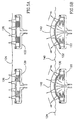
- Fig. 1 presenting the principal components of a massaging element in accordance with the present invention generally designated 20 .
- the massaging element comprises a cylindrical housing 22 fitted with an inlet tube 24 terminating at inlet port 26 within housing 22 .
- Housing 22 is further formed wit a laterally extending recess 28 and an annular shoulder 30 , the purpose of which will become apparent hereinafter.
- a support diaphragm 34 comprises an essentially flat support portion 36 , a bellows-type portion 38 and a skirt portion 40 , the edges of which being adapted for sealingly and fixedly receiving within annular recess 28 of housing 22 .
- a pressure chamber 42 In the assembled position (best seen in Figs. 2), there is formed a pressure chamber 42 .
- a massaging cushion 46 is essentially circular and comprises, on a top surface thereof 48 , a plurality of bulges 50 , each having a tapering cross-section with a longitudinal axis extending essentially normal to surface 48 .
- Each of the bulges 50 comprises a rounded massaging tip 52 and as can be seen in Fig. 1, the bulges are disposed on the surface 48 at an essentially circular pattern.
- a retaining ring 60 is provided for securing massaging cushion 48 to the housing. Retaining ring 60 is adapted for snap engagement with the housing, as can be seen in Figs. 2.
- pressure port 26 extends into chamber 42 .
- the arrangement is such that upon applying pressure of fluid, typically pneumatic pressure, as seen in Fig. 2b, the .........'s portion 38 of support member 34 expands, entailing the formation of support portion 36 into a spherical shape, consequencing in corresponding the formation of massaging cushion 46 .
- the massaging element 20 In the position seen in Fig. 2a, the massaging element 20 is in the deflated position and when applied to skin 70 of an individual, pressure is applied only in a normal direction represented by arrow 72 extending parallel to longitudinal axis of the bulges 50 .
- support member 34 Upon pressurizing pressure chamber 42 , support member 34 deforms such that the support surface 36 and the massaging cushion 46 assume a spherical shape.
- bulges 50 When applied to skin 70 , bulges 50 are displaced in a direction having a first displacement component 76 in any direction corresponding with the longitudinal axis of the bulges and which is essentially normal to the skin surface, and a second displacement component represented by arrows 78 , being in a direction essentially normal to said first displacement component 76 , i.e. essentially parallel to the surface of the skin.
- the massaging element 20 applies simultaneous pressure in first direction normal to the surface of the skin, and in a second direction essentially perpendicular thereto.
- This arrangement provides on the one hand pressure and on the other hand yields retracting and contracting force onto the skin of the individual.
- the massaging element is adapted only for pneumatic operation
- the arrangement is such that the inflation flow rate is higher than the deflation (bleeding) flow rate, whereby the duration of inflated state of the massaging element depends on the dimensions of the bleeding aperture.
- Fig. 3 illustrating a preferred embodiment of a massaging cushion generally designated 80 .
- the surface 82 comprises several bay-like cut-outs 84 for imparting the massaging cushion 82 improved flexibility, in order to assume its spherical shape in the inflated state.
- Massaging cushion 80 further differs from the massaging cushion 46 in Figs. 1 and 2 in that the bulges 86 are inwardly inclined, having their longitudinal axes intersecting at an imaginary point above the surface 82 .
- a massaging cushion generally designated 90 , in which the massaging bulges 92 are frastoconical and extend at an inclination, as in Fig. 3.
- the bulges are provided at their end with a receptacle 94 for snappingly receiving a replaceable tip 98 seen in Fig. 4B.
- Tip 98 comprises a rounded surface 100 , which in an assembled position coincides with the contour of the bulges 92 .
- Member 98 is fitted with a stem 102 and an engagement bulge 104 for snappingly engagement within a receptacle 94 of bulge 92 .
- other arrangements for attaching the tips are also possible, e.g. screw fitting, etc.
- the massaging cushion is integrally formed with the bulges and the rounded tips and is typically made of a rubber or a silicone rubber material
- the massaging cushion 90 and bulges 92 are made of a resilient material
- the tips 98 are made of an essentially rigid material such as plastic.
- the massaging tips be machined to reduce the friction coefficient, e.g. by polishing.
- the massaging tips 98 may be replaced by a suitable member provided with micro-capsules comprising moisturizing agents, lubricants, odor agents etc.
- FIGs. 5A and 5B illustrating the massaging effect of two enabling massaging elements in accordance with the present invention, constituting a section of a massaging system.
- massaging elements 120 and 122 are of any one of the massaging elements illustrated in the previous embodiments.
- massaging elements 120 and 122 are in a deflated position and when applied to skin 124 they apply only a pressure in direction of arrows 126 , which is essentially normal to skin 124 .
- a massaging system in accordance with the present invention.
- a massaging system is useful, for example, in medical institutes and it comprises an electrically operated pressure source generally designated 150 connected via suitable typing and wiring 152 and 154 to a massaging chair 156 and a massaging bed 158 , respectively.
- Each of the massaging chairs 156 and massaging bed 158 is fitted with a programmable controller 160 which independently controls different pressure parameters, e.g. pressure rate, pressure intervalves, flow rate and also control of different regions as may be required, i.e. portions corresponding with the back of the individual.
- a mat fitted with a plurality of massaging elements which may be applied by a user on any surface.
- a massaging cushion 180 having a boomerang-like shape and fitted with a plurality of bulges 182 .
- the massaging cushion in accordance with this embodiment is suitable in particular for massaging a person's back. It will be noted that a variety of designs for massaging cushions may be provided, each adapted for a different body part.
- FIG. 8 illustrating a foot massaging device generally designated 190 and comprising a water tight housing 192 with a base mat 194 shaped for supporting two feet.
- the mat 192 fitted with a plurality of massaging elements 194 as disclosed hereinabove.
- the device further comprises a plurality of under-jet nozzles 196 and side-jet nozzles 198 .
- a control 200 selects a plan which controls water temperature, water jet pressure messaging parameters (e.g. speed, one or both feet, etc). It is appreciated that the air pressure used for operating the massaging elements may be used for generating the water jets.
- a friction reducing material such as a fabric having at least an inner surface made of or coated with a friction reducing material such as silk or other synthetic cloth, nylon, etc.
- a friction reducing material such as a fabric having at least an inner surface made of or coated with a friction reducing material such as silk or other synthetic cloth, nylon, etc.
- the one or more massaging elements of a massaging system are all received within a suitable enveloping friction reducing member, as can readily be understood.
- a friction reducing layer between the massaged surface and the massaging elements.
- One such example may be providing a manually held massaging device comprising massaging elements as described, and comprising a source of compressed air, e.g. a portable balloon.
Landscapes
- Health & Medical Sciences (AREA)
- Public Health (AREA)
- Epidemiology (AREA)
- Pain & Pain Management (AREA)
- Physical Education & Sports Medicine (AREA)
- Rehabilitation Therapy (AREA)
- Life Sciences & Earth Sciences (AREA)
- Animal Behavior & Ethology (AREA)
- General Health & Medical Sciences (AREA)
- Veterinary Medicine (AREA)
- Massaging Devices (AREA)
Applications Claiming Priority (2)
| Application Number | Priority Date | Filing Date | Title |
|---|---|---|---|
| IL12973299 | 1999-05-03 | ||
| IL12973299A IL129732A0 (en) | 1999-05-03 | 1999-05-03 | Massaging device |
Publications (2)
| Publication Number | Publication Date |
|---|---|
| EP1050290A2 true EP1050290A2 (de) | 2000-11-08 |
| EP1050290A3 EP1050290A3 (de) | 2002-03-27 |
Family
ID=11072757
Family Applications (1)
| Application Number | Title | Priority Date | Filing Date |
|---|---|---|---|
| EP00109378A Withdrawn EP1050290A3 (de) | 1999-05-03 | 2000-05-02 | Massagegerät |
Country Status (2)
| Country | Link |
|---|---|
| EP (1) | EP1050290A3 (de) |
| IL (1) | IL129732A0 (de) |
Cited By (5)
| Publication number | Priority date | Publication date | Assignee | Title |
|---|---|---|---|---|
| DE102006002228A1 (de) * | 2006-01-17 | 2007-07-26 | Schukra Gerätebau AG | Massageelement |
| EP2108352A1 (de) * | 2008-04-10 | 2009-10-14 | Aqualife S.r.l. | Matratze zur Erzeugung eines Trockenmassageeffekts ähnlich dem Shiatsu und Kombination einer solchen Matratze mit einer Hydromassageeinheit |
| EP2967956A4 (de) * | 2013-03-15 | 2017-03-22 | Trudell Medical International | Mundstück und verfahren zur verwendung davon |
| CN109330844A (zh) * | 2018-10-23 | 2019-02-15 | 陈金城 | 拉力式背部按摩健身器材 |
| WO2021164915A1 (de) * | 2020-02-19 | 2021-08-26 | Audi Ag | Massagesystem |
Citations (4)
| Publication number | Priority date | Publication date | Assignee | Title |
|---|---|---|---|---|
| US3403862A (en) | 1967-01-06 | 1968-10-01 | Du Pont | Apparatus for preparing tanglelaced non-woven fabrics by liquid stream jets |
| US4177803A (en) | 1977-08-29 | 1979-12-11 | Papistas Scherer Bertha | Foot exerciser |
| US4197837A (en) | 1977-10-04 | 1980-04-15 | American Hospital Supply Corporation | Inflatable-deflatable pad and air control system therefor |
| US5607749A (en) | 1994-12-27 | 1997-03-04 | Strumor; Mathew A. | Ergonomic kinetic acupressure massaging system |
Family Cites Families (8)
| Publication number | Priority date | Publication date | Assignee | Title |
|---|---|---|---|---|
| GB262520A (de) * | 1900-01-01 | |||
| BE409188A (de) * | ||||
| GB295375A (de) * | 1927-08-12 | 1929-07-11 | Carl Grosse | |
| CH167647A (de) * | 1933-03-10 | 1934-02-28 | Walker Benno | Vibrations-Massageapparat, insbesondere für den Anschluss an das Saugrohr eines Staubsaugers. |
| FR978554A (fr) * | 1948-11-18 | 1951-04-16 | Vibro-masseur pneumatique | |
| FR2321874A1 (fr) * | 1975-08-29 | 1977-03-25 | Sajot Alain | Generateur de pulsations pneumatiques pour appareils de relaxation, massage et kinesitherapie |
| US4139001A (en) * | 1976-10-08 | 1979-02-13 | Macabee Lloyd C | Hydro-massage and pulsator apparatus |
| DE19709759C1 (de) * | 1997-03-10 | 1998-10-01 | Dueker Eisenwerk | Massagegerät |
-
1999
- 1999-05-03 IL IL12973299A patent/IL129732A0/xx unknown
-
2000
- 2000-05-02 EP EP00109378A patent/EP1050290A3/de not_active Withdrawn
Patent Citations (4)
| Publication number | Priority date | Publication date | Assignee | Title |
|---|---|---|---|---|
| US3403862A (en) | 1967-01-06 | 1968-10-01 | Du Pont | Apparatus for preparing tanglelaced non-woven fabrics by liquid stream jets |
| US4177803A (en) | 1977-08-29 | 1979-12-11 | Papistas Scherer Bertha | Foot exerciser |
| US4197837A (en) | 1977-10-04 | 1980-04-15 | American Hospital Supply Corporation | Inflatable-deflatable pad and air control system therefor |
| US5607749A (en) | 1994-12-27 | 1997-03-04 | Strumor; Mathew A. | Ergonomic kinetic acupressure massaging system |
Cited By (7)
| Publication number | Priority date | Publication date | Assignee | Title |
|---|---|---|---|---|
| DE102006002228A1 (de) * | 2006-01-17 | 2007-07-26 | Schukra Gerätebau AG | Massageelement |
| DE102006002228B4 (de) * | 2006-01-17 | 2007-11-15 | Schukra Gerätebau AG | Massageelement |
| EP2108352A1 (de) * | 2008-04-10 | 2009-10-14 | Aqualife S.r.l. | Matratze zur Erzeugung eines Trockenmassageeffekts ähnlich dem Shiatsu und Kombination einer solchen Matratze mit einer Hydromassageeinheit |
| EP2967956A4 (de) * | 2013-03-15 | 2017-03-22 | Trudell Medical International | Mundstück und verfahren zur verwendung davon |
| CN109330844A (zh) * | 2018-10-23 | 2019-02-15 | 陈金城 | 拉力式背部按摩健身器材 |
| WO2021164915A1 (de) * | 2020-02-19 | 2021-08-26 | Audi Ag | Massagesystem |
| CN115175650A (zh) * | 2020-02-19 | 2022-10-11 | 奥迪股份公司 | 按摩系统 |
Also Published As
| Publication number | Publication date |
|---|---|
| EP1050290A3 (de) | 2002-03-27 |
| IL129732A0 (en) | 2000-02-29 |
Similar Documents
| Publication | Publication Date | Title |
|---|---|---|
| US6517500B2 (en) | Massager having treatment members adapted to be moved in an arc shape | |
| US3483862A (en) | Massaging apparatus | |
| US6916300B2 (en) | Seat massager | |
| JP2620445B2 (ja) | 人間工学的な抗疲労着座装置 | |
| US6336907B1 (en) | Massaging system | |
| US6560803B2 (en) | Pressure relief pneumatic area support device and system | |
| KR100190594B1 (ko) | 의자식 공기 마사지 장치(air massage device of chair type) | |
| EP1832268A1 (de) | Massagesystem und Verfahren zur Massage eines Patienten | |
| JPH10118143A5 (de) | ||
| CN115381693A (zh) | 具有气室设备的按摩椅组件及其提供方法 | |
| EP0799009A1 (de) | Stuhl mit wadenstütze | |
| CN217660659U (zh) | 按摩装置 | |
| JP3806396B2 (ja) | 手揉機能付施療機 | |
| JPH11244347A (ja) | エアーマッサージ機 | |
| JP4516173B2 (ja) | マッサージ枕 | |
| WO2006065242A1 (en) | Massaging device | |
| JP2000051302A (ja) | マッサージ機 | |
| JPH0938165A (ja) | マット状エアマッサージ器 | |
| CN223041789U (zh) | 按摩装置组装体 | |
| JP2007307179A (ja) | 肩等のマッサージ器具及びマッサージ機能を備えた腰掛け具 | |
| JP3257752B2 (ja) | 椅子式エアーマッサージ機 | |
| JP7742538B2 (ja) | マッサージ装置 | |
| JP4444615B2 (ja) | エアーマッサージ機 | |
| CN217660667U (zh) | 按摩装置 | |
| JP2001212190A (ja) | マッサージ装置 |
Legal Events
| Date | Code | Title | Description |
|---|---|---|---|
| PUAI | Public reference made under article 153(3) epc to a published international application that has entered the european phase |
Free format text: ORIGINAL CODE: 0009012 |
|
| AK | Designated contracting states |
Kind code of ref document: A2 Designated state(s): AT BE CH CY DE DK ES FI FR GB GR IE IT LI LU MC NL PT SE |
|
| AX | Request for extension of the european patent |
Free format text: AL;LT;LV;MK;RO;SI |
|
| PUAL | Search report despatched |
Free format text: ORIGINAL CODE: 0009013 |
|
| AK | Designated contracting states |
Kind code of ref document: A3 Designated state(s): AT BE CH CY DE DK ES FI FR GB GR IE IT LI LU MC NL PT SE |
|
| AX | Request for extension of the european patent |
Free format text: AL;LT;LV;MK;RO;SI |
|
| AKX | Designation fees paid | ||
| STAA | Information on the status of an ep patent application or granted ep patent |
Free format text: STATUS: THE APPLICATION IS DEEMED TO BE WITHDRAWN |
|
| 18D | Application deemed to be withdrawn |
Effective date: 20021203 |
|
| RIN1 | Information on inventor provided before grant (corrected) |
Inventor name: PLESHCHINSKI, MICHAEL Inventor name: TZITRIN, ARKADI Inventor name: AVIGDOR, AMIT |