EP1050466A1 - Procede et appareil pour emballer des articles dans un film retractable - Google Patents
Procede et appareil pour emballer des articles dans un film retractable Download PDFInfo
- Publication number
- EP1050466A1 EP1050466A1 EP00109387A EP00109387A EP1050466A1 EP 1050466 A1 EP1050466 A1 EP 1050466A1 EP 00109387 A EP00109387 A EP 00109387A EP 00109387 A EP00109387 A EP 00109387A EP 1050466 A1 EP1050466 A1 EP 1050466A1
- Authority
- EP
- European Patent Office
- Prior art keywords
- air
- film
- shrink tunnel
- shrink
- areas
- Prior art date
- Legal status (The legal status is an assumption and is not a legal conclusion. Google has not performed a legal analysis and makes no representation as to the accuracy of the status listed.)
- Withdrawn
Links
- 238000004806 packaging method and process Methods 0.000 title claims abstract description 16
- 238000000034 method Methods 0.000 title claims description 22
- 239000011888 foil Substances 0.000 title claims description 16
- 238000010438 heat treatment Methods 0.000 claims description 22
- 229920006300 shrink film Polymers 0.000 claims description 15
- 230000008859 change Effects 0.000 claims description 5
- 230000008569 process Effects 0.000 claims description 4
- 239000004065 semiconductor Substances 0.000 claims description 4
- 238000012856 packing Methods 0.000 claims description 2
- 238000005304 joining Methods 0.000 abstract description 2
- 238000009826 distribution Methods 0.000 description 10
- 230000009471 action Effects 0.000 description 5
- 230000008901 benefit Effects 0.000 description 5
- 239000004698 Polyethylene Substances 0.000 description 3
- 238000007664 blowing Methods 0.000 description 3
- 238000003466 welding Methods 0.000 description 3
- 230000009286 beneficial effect Effects 0.000 description 2
- 210000005069 ears Anatomy 0.000 description 2
- 230000002829 reductive effect Effects 0.000 description 2
- 238000007665 sagging Methods 0.000 description 2
- 238000012546 transfer Methods 0.000 description 2
- 230000002411 adverse Effects 0.000 description 1
- 230000004888 barrier function Effects 0.000 description 1
- 238000009529 body temperature measurement Methods 0.000 description 1
- 230000015556 catabolic process Effects 0.000 description 1
- 230000003247 decreasing effect Effects 0.000 description 1
- 238000001514 detection method Methods 0.000 description 1
- 238000005265 energy consumption Methods 0.000 description 1
- 230000002349 favourable effect Effects 0.000 description 1
- 230000005484 gravity Effects 0.000 description 1
- 230000006872 improvement Effects 0.000 description 1
- 239000011261 inert gas Substances 0.000 description 1
- 238000009434 installation Methods 0.000 description 1
- 238000009413 insulation Methods 0.000 description 1
- 239000000155 melt Substances 0.000 description 1
- 230000003446 memory effect Effects 0.000 description 1
- 238000000465 moulding Methods 0.000 description 1
- 238000012858 packaging process Methods 0.000 description 1
- 230000036961 partial effect Effects 0.000 description 1
- -1 polyethylene Polymers 0.000 description 1
- 229920000573 polyethylene Polymers 0.000 description 1
- 229920000098 polyolefin Polymers 0.000 description 1
- 238000003825 pressing Methods 0.000 description 1
- 230000001681 protective effect Effects 0.000 description 1
- 230000009467 reduction Effects 0.000 description 1
- 238000011144 upstream manufacturing Methods 0.000 description 1
Images


Classifications
-
- B—PERFORMING OPERATIONS; TRANSPORTING
- B65—CONVEYING; PACKING; STORING; HANDLING THIN OR FILAMENTARY MATERIAL
- B65B—MACHINES, APPARATUS OR DEVICES FOR, OR METHODS OF, PACKAGING ARTICLES OR MATERIALS; UNPACKING
- B65B53/00—Shrinking wrappers, containers, or container covers during or after packaging
- B65B53/02—Shrinking wrappers, containers, or container covers during or after packaging by heat
- B65B53/06—Shrinking wrappers, containers, or container covers during or after packaging by heat supplied by gases, e.g. hot-air jets
- B65B53/063—Tunnels
Definitions
- the invention relates to a method and an apparatus for Packing items in shrink wrap, the Shrink wrap essentially surrounds and in a shrink tunnel connected by moving hot air, is closed and / or shrunk.
- the invention has for its object a method and to further improve a device of the type mentioned at the outset, in particular, the shrinkage of the film is said to be more uniform and done stronger.
- This task is due to the characteristics of claim 1 solved.
- a non-contact Influencing individual areas of the film has the advantage that they are before, during or after heat shrinkage the film is not too heavily loaded, in particular not through corners or edges of mechanical devices. Furthermore, the hot air in the tunnel can be realized better become.
- the hot air can be widely distributed in the shrink tunnel or be moved, especially by an essentially slow or moderate upheaval.
- the additional Targeted exposure to rapidly flowing air for example essentially punctiform by at least one Air jet.
- the movement speed of the circulated Hot air is normally 2 when the outlet is free up to 4 m / s; in part, for example 50% closed Air inlets for hot air up to 11 m / s.
- the fast flowing Air of the additional application is advantageous in Compared to the revolution quickly, for example at one speed from 11 m / sec up to 22 m / sec, especially in Exit area.
- Compressed air can be used with a pressure of 2 bar to 7 bar, preferably about 6 bar can.
- compressed air from a fixed installation Compressed air system as is common in assembly halls can be found used.
- the volume of the rapidly flowing air is advantageous a fraction of the volume inside the shrink tunnel permanently introduced or circulated hot air, the proportion can be between 1% and 20%, in particular Is 2 to 5%. From this it is clear that relatively little Air is additionally introduced into the shrink tunnel, in particular in order not to close the temperature control in cold air complicate.
- the additional air can be continuous or pulsed or be introduced in interval operation.
- the film can at least partially cold air is blown, such as one Compressed air system is removable. Introducing a targeted, especially cold, air flow can arise through Turbulence can be beneficial. It is for emergence of eddies not only necessary, only to blow the film. Additionally or alternatively, the Heated air is applied to and / or blown onto the film become.
- the air is heated by a heating device possible for the shrink tunnel, for example can do this Hot air branched off from the shrink tunnel and for blowing the film can be compressed.
- any area of the Shrink film are applied or blown.
- Advantageous essentially loose areas of film are applied, i.e. those that are not on the object or an outside contour surface run along. At least one-sided open hose wrapping this can close the film areas the or for the opening.
- preferably essentially those seen in the direction of travel of the object Sides and / or the underside of the object or the associated film areas are applied.
- By the application can be foil areas that in particular are at least partially loose, towards the object and / or to be moved towards each other. This is a non-contact
- the film areas can be folded to the desired extent, for example in a similar way as when wrapping a gift the open pages are wrapped in succession and placed on top of each other. It can be seen that thus great progress in packaging quality, closure quality (due to better overlap of the to be connected Film areas) and film consumption can be achieved can.
- the application of film areas with fast flowing Air can take place in a changeable direction.
- a change The direction of exposure can be essentially within further areas occur, it advantageously changes along the continuous path, especially with the object running along. Essentially a lateral one is preferred Loading, but it is also loading forward and / or aft direction and from below possible.
- a controllable additional application is advantageous viewed, especially with regard to the direction of exposure, Speed and / or air volume controllable.
- Speed and / or air volume controllable For example can essentially be applied in each case take place where the object is in its trajectory located.
- the object can be adjusted using suitable sensors like light barriers or the like be located.
- an application can be made in the area take place outside the shrink tunnel, preferred before entering the object in the shrink tunnel.
- the film can be preformed or into a shrinkage of the film and / or to enable closure of overlapping film areas and favorable form. In particular can do this in the manner of a contactless pre-folding of the film respectively.
- An application within is particularly preferred of the shrink tunnel, especially at least in the beginning and / or End area of the shrink tunnel.
- Hot air circulation deviating turbulence can be generated. Such swirling is advantageous at least from middle area of the shrink tunnel used.
- the direction of exposure can be oblique to the horizontal, for example at an angle between 10 ° and 90 °, especially between 45 ° and 80 °.
- a method is thus possible in which the shrinkage and / or a closure of the film in the shrink tunnel Slow circulation of hot air takes place and through the additional Moving freely moving air and brought together unclosed film areas and be connected by the hot air. At least one partial loading from below can raise the Connection area of several film areas from the lower edge cause the object to move upwards.
- the temperature in the shrink tunnel is preferably achieved by Regulation in a the shrinkage and / or connection of the Foil causing temperature range kept, for regulation detects the temperature with at least one temperature sensor and from a certain temperature drop on a heater is adjusted for the circulating hot air.
- the heating device is preferably switched very much fast.
- an electrical Heating device electronic load relays' are used in particular semiconductor switches, such as IGBTs or MOSFET's.
- a packaging device with a shrink tunnel for Objects essentially surrounded by shrink wrap are, the objects in the shrink tunnel with hot air are treated to shrink and / or join the
- a film can be a discharge device to act upon the film with rapidly flowing air or an appropriate medium in addition to the hot air treatment exhibit.
- Fast flowing air can be considered mechanical Action on the shrink film, for example as Replacement of pressure rollers arranged after a shrink tunnel, be used. In particular, flowing under fast Viewed speeds between 11 m / sec and 22 m / sec, in any case, the speed of the hot air flow be exceeded significantly.
- a discharge device can run at least partially along extend a trajectory of the objects, wherein they is preferably distributed. At least is preferred a discharge device in the lower area of the continuous path provided, in particular additional discharge devices in the side area.
- a discharge device can have at least one duct or channel for the air, especially with outlet openings for the quick flowing air.
- the outlet openings can be holes and / or slots are formed.
- Adjustment means are advantageous for direction and / or opening cross sections of the Outlet openings provided, in particular an adjusting means for multiple openings.
- the direction of at least one part the outlet openings or the air flow can be in one Angles between 10 ° and 90 ° run obliquely to the horizontal, especially between 45 ° and 80 °.
- a discharge device can be arranged in front of the shrink tunnel Have outlet openings, in particular for pre-folding at least partially free film areas to be connected to be aligned obliquely to these film areas can. This enables a contactless pre-folding of the Areas of film before heat is applied to the shrink film.
- the discharge device is particularly preferably essentially arranged in the shrink tunnel, the outlet openings on the one hand to fold and overlap more freely connecting film areas and / or for molding or pressing shrinking or shrinking film, especially on the Object can be formed. You can also go to Generation of turbulence. Advantageous they are similar to the above version slanted.
- the packaging device can be a controller with a temperature control for heating the shrink tunnel.
- at least one temperature sensor can be provided be preferably in the upper area of the shrink tunnel interior or be arranged on an air intake can.
- the heater is preferably electrical, wherein they in particular have at least one tubular heater can in one of recirculated or heated air flowed through channel.
- the controller can also Have switching means for a heating device of the heating, especially semiconductor switches.
- the shrink tunnel can be designed as a two-shell system, with in the intermediate shell at least the circulation, possibly also the heating of the Hot air tracks, especially a part of the discharge device can run.
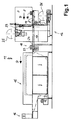
- FIG. 1 shows a packaging line known in principle 11, which is a banding station 12, a shrink tunnel 15 and has an outlet station 16. Through these stations a multi-sectioned belt conveyor 17 runs through it Objects 18 successively in the direction D through the individual stations. Details on this, especially the Banding station 12, for example EP 718 198 A1 or the known prior art. Noteworthy is only that in the banding station 12th from two shrink film webs 23, 24, made of supply rolls 25 and 26 processed above and below the conveyor level 17 a film curtain is formed. In these The object 18 is pushed into the film curtain. The possibly film that is fed in synchronously with the movement lies in the embodiment closely around the front edge and over the Top and bottom of the object up to the rear edge out.
- the film webs are made by a further device 23 and 24 separated and on the separated sides welded together.
- the object 18 is thereby with surrounded by a closed band, the front and Trailing edge each has a weld seam and provisionally on both Sides is open, there the film is a good deal protrudes beyond the side edges.
- the objects 18 run in the Shrink tunnel 15 into it. There is described on below Way the film shrunk onto the object and possibly connected to a closed bag. The one from the Shrink tunnel 15 emerging items 18 are in the Outlet station 16 taken over and transported on.
- FIG. 2 shows schematically one possible embodiment for a shrink tunnel 15 with a discharge device arranged in front of it 40, being in a substantially usual manner is provided with heating. A revolution is on many Ways to achieve.
- the heating shows schematically shown an air circulator 27 including drive 28, the Air is extracted from inside the shrink tunnel 15 and inside a channel 30 past tubular heaters 31. Subsequently the heated air can return to the inside of the Shrink tunnels 15 enter, via hot air outlets 55 on the side walls and / or the ceiling or the floor of the Shrink tunnels.
- the hot air outlets are mostly like blinds provided in hot air ducts 56 and with respect to direction and passage cross section adjustable.
- outlet nozzles 38 are arranged on the portal 33, which are also connected to the connecting line 35 are.
- the outlet nozzles 38 run obliquely against the Passage direction D and are essentially towards the center of the object 18 to be aligned. That means the two upper outlet nozzles point downwards, the lower outlet nozzle however, points obliquely upwards.
- the cross sections of the outlet openings or outlet nozzles should be relatively small, for example not larger than 2 cm, especially 2 - 3 mm.
- Relatively sharp air jets are considered advantageous because, on the one hand, they are more precise Enable application and on the other hand the introduced Volume is lower.
- An expansion of an air jet results from the distance of some alone Centimeter. The fast air also sweeps away the hot air.
- FIG. 3 is a further embodiment of a Shrink tunnel 15 shown schematically, with the help of this representation an execution possibility for a in the discharge device 40 attached to the shrink tunnel becomes.
- a in the discharge device 40 attached to the shrink tunnel becomes.
- the illustration of the air circulator 27 together with channel 30 for heating of the shrink tunnel 15 has been dispensed with. It goes without saying that the shrink tunnel 15 in Fig. 3 such heating assigned.
- Distribution channels 41 are along the inner long sides of the shrink tunnel 15 Distribution channels 41 attached, which are essentially over extend its length.
- the upper distribution channel 41 has outlet openings 34 for the discharge of additionally introduced Air on.
- the lower distribution channel 41 has outlet nozzles 38 on that are aligned increasingly flatter in the direction of flow D. are.
- Another distribution channel 41 is indicated by dashed lines, which runs obliquely in the direction of flow D, in particular with decreasing height, not shown Have outlet openings 34 and / or outlet nozzles 38 can.
- the passage area of the object 18 is by means of further outlet nozzles 38 on a further distribution channel 41 acted upon.
- These outlet nozzles can be used with different Direction, as shown, the it is also possible to make them movable.
- the Distribution channel 41 running below the belt conveyor 17 can either run parallel to the direction D, or in one to the transport plane of the object parallel plane run obliquely.
- All distribution channels 41 are dash-dotted Connection line 35 with a compressed air line 36 or interconnected, the for the compressed air line 2 applies.
- a shut-off valve 42 is shown to the Compressed air supply to this distribution channel or its outlet openings and thus control the amount applied or to be able to park.
- Shut-off valves 42 of this type can each distribution channel 41, or the entire discharge device 40 assigned.
- Fig. 4 is an article 18 from a shrink wrap surrounded by an upper shrink film 23 and a lower shrink film sheet 24. On front and The foils are connected on the back with a weld seam 44. First, free areas 46 of the upper film web pressurized with compressed air in the direction of arrows B. This should first of all be done by gravity free areas of film hanging downwards against the lateral surfaces of the object 18 are created. The free film areas 48 of the lower web 24 are still in essentially flat on the base, for example one Belt conveyor.
- the air circulator 27, ie the hot air blower for the normal circulating air used for shrinking, can circulate in one embodiment approx. 2.7 m 3 / min, ie past the tubular heating elements 31 through the hot air channels 56, the hot air outlets 55 and the shrink tunnel interior back to the blower inlet .
- FIG. 6 shows how the lower areas of the film 48 up over the upper areas 46 and against the Sides of the object 18 are folded or placed. Similar as with the loading B is also with the loading C changed the direction more towards the horizontal, in particular only slightly upwards. This will make the film sheets or the free areas 46 and 48 in one for the Joining or welding the foil by hot air and preferably tightly closing the band setting held.
- Another advantage of an application C from below is that the connection area of the Foil webs at the opposite ends of the object, where the film webs together in the shrink tunnel be welded from the bottom edge of the object can be lifted upwards. So a sagging or sagging of this connection area avoided become.
- the object 18 inserted into a foil band if possible clean, evenly and completely enclosed or closed become.
- this can advantageously be done in the manner, for example a box is wrapped in wrapping paper.
- the film overhang is on one side of the object first on two opposite areas of one side placed or folded inwards against the object, then first on one of the remaining film areas and finally the last film area folded against the side of the item. The same is done on the opposite side of the Subject repeated.
- Fig. 7 is a top view of an object 18, of a sleeve made of an upper and lower shrink film 23 and 24 is wrapped.
- the modified is shown in dashed lines Acting direction E to the film areas as in a To be able to perform folding as desired.
- a pre-fold first the lateral foil areas has the advantage that here for two opposite areas on one side the same Conditions apply, unlike a hanging one Area 46 and a flat area 48.
- Dog ears in principle Dog ears
- a particularly advantageous example provides, however, through the improved shrinkage of the Film shrink this smooth, especially the shrinkability 100% use of the foils to create an appealing To achieve optics of the packaging.
- Air especially if it should be cold of the total air introduced, which is hot air, is low should be, especially in the range of a few percent. Thereby the change in the desired temperature is introduced by Cold air kept low. To enable good regulation, it should be modified accordingly.
- a possibility this consists, in particular, of an electrical one Heating device, for controlling semiconductor switches use. This enables, especially in connection with a zero-crossing control of the switching elements fast and frequent switching to responsive and precise control of the temperature in a desired range.
- the turbulence resulting from the additional exposure, in particular to cold air can improve the shrinkage of the film.
- the breakdown of the boundary layers through the swirling with additionally introduced air enables an improvement in the heat input into the film. It can thereby be achieved that the temperature at and thus in the film itself corresponds relatively exactly to the shrink tunnel temperature.
- the reduction in the temperature gradient enables the required temperature in the tunnel to be reduced and thus the energy consumption.
- the compressed air consumption is relatively low. In the above example, it is between 0.0275 and 0.11 m 3 / min, ie 1 to 5% of the amount of hot air circulated.
- the shrinking process can be used on the one hand for polyethylene film (PE film) and on the other hand adapted for polyolefin film (PO film) become.
- PE film polyethylene film
- PO film polyolefin film
- a temperature window is usually used for PO films 150 ° C - 180 ° C tunnel temperature used. About that melts the film. Even at 120 ° C - 130 ° C achieve shrinkage results according to the new process that otherwise only from 150 ° C (temperature measurement as above) explained) were possible. This enables immense energy savings.
- a shrink tunnel can be used for the same throughput build shorter (especially with less power) the same length or performance results in a higher throughput.
- the invention is also advantageous for packaging, at which the object is not only surrounded by a foil band, but is completely enclosed and welded in (full wrapping). There too, you can use the additional, possibly targeted High-speed air jets not only the film wrapping particularly even and visually appealing as well favorably affect strength, but also the Improve heat transfer on the film, so that shorter if necessary Shrink tunnels are possible.
Landscapes
- Engineering & Computer Science (AREA)
- Mechanical Engineering (AREA)
- Packages (AREA)
- Shaping By String And By Release Of Stress In Plastics And The Like (AREA)
Applications Claiming Priority (2)
| Application Number | Priority Date | Filing Date | Title |
|---|---|---|---|
| DE1999120057 DE19920057A1 (de) | 1999-05-03 | 1999-05-03 | Verfahren und Vorrichtung zur Verpackung von Gegenständen in Schrumpffolie |
| DE19920057 | 1999-05-03 |
Publications (1)
| Publication Number | Publication Date |
|---|---|
| EP1050466A1 true EP1050466A1 (fr) | 2000-11-08 |
Family
ID=7906645
Family Applications (1)
| Application Number | Title | Priority Date | Filing Date |
|---|---|---|---|
| EP00109387A Withdrawn EP1050466A1 (fr) | 1999-05-03 | 2000-05-03 | Procede et appareil pour emballer des articles dans un film retractable |
Country Status (2)
| Country | Link |
|---|---|
| EP (1) | EP1050466A1 (fr) |
| DE (1) | DE19920057A1 (fr) |
Cited By (4)
| Publication number | Priority date | Publication date | Assignee | Title |
|---|---|---|---|---|
| WO2014009529A1 (fr) * | 2012-07-12 | 2014-01-16 | Sleever International Company | Installation de thermoretraction comportant des moyens de diffusion de chaleur formant un ensemble unitaire |
| EP2722280A1 (fr) * | 2012-10-17 | 2014-04-23 | Cryovac, Inc. | Procédé d'emballage et appareil d'emballage |
| EP3323432A3 (fr) * | 2016-11-16 | 2018-10-17 | Massimo Boldrini | Appararail de stérilisation et de depyrogenisation |
| US20240270429A1 (en) * | 2021-06-09 | 2024-08-15 | Cryovac, Llc | Heat shrink apparaus and device for packaging, and packaging line and process using said heat shrink apparatus and device |
Families Citing this family (12)
| Publication number | Priority date | Publication date | Assignee | Title |
|---|---|---|---|---|
| DE102006036590A1 (de) † | 2006-08-04 | 2008-02-07 | Khs Ag | Verfahren zum Aufschrumpfen einer Schrumpffolie auf Verpackungen sowie Vorrichtung zum Durchführen des Verfahrens |
| DE102008052633A1 (de) | 2008-10-22 | 2010-04-29 | Khs Ag | Verfahren und Vorrichtung zur Herstellung einer Verpackungseinheit |
| DE102009044465A1 (de) * | 2009-11-09 | 2011-05-12 | Krones Ag | Schrumpftunnel |
| DE102010011640B4 (de) * | 2010-03-16 | 2020-03-12 | Khs Gmbh | Schrumpftunnel zum Aufbringen von Schrumpffolien, Verfahren zum Betrieb oder Steuern eines Schrumpftunnels sowie Produktionsanlage mit einem Schrumpftunnel |
| DE102013215415A1 (de) * | 2013-08-06 | 2015-02-12 | Krones Aktiengesellschaft | Verfahren und Vorrichtung zum Schrumpfen von Materialien auf Artikel und/oder auf eine Zusammenstellung von Artikeln |
| DE102016118233A1 (de) | 2016-09-27 | 2018-03-29 | Rkw Se | Schrumpffolienverpackung |
| DE202018101776U1 (de) * | 2018-03-29 | 2019-07-31 | Krones Ag | Dampfbalken und Schrumpftunnel |
| DE102020120705A1 (de) | 2020-08-05 | 2022-02-10 | Krones Aktiengesellschaft | Verfahren und Schrumpfvorrichtung zum Aufschrumpfen eines thermoplastischen Verpackungsmaterials auf Artikel |
| EP3812288B1 (fr) | 2019-10-25 | 2023-09-06 | Krones Aktiengesellschaft | Procédé et dispositif de rétractation destinés à la rétractation d'une matière d'emballage thermoplastique sur des articles |
| DE102020208108A1 (de) | 2020-06-30 | 2021-12-30 | Krones Aktiengesellschaft | Schrumpftunnel und Verfahren zum Aufschrumpfen von thermoplastischem Verpackungsmaterial |
| DE102022114548A1 (de) | 2022-06-09 | 2023-12-14 | Krones Aktiengesellschaft | Schrumpfvorrichtung und ein Verfahren zum Aufschrumpfen thermoplastischen Verpackungsmaterials |
| DE102024110670A1 (de) | 2024-04-16 | 2025-10-16 | Jens Kallfass | Verfahren und Vorrichtung zum Verpacken von Gegenständen und Verwendung einer Folie für dieses Verfahren |
Citations (6)
| Publication number | Priority date | Publication date | Assignee | Title |
|---|---|---|---|---|
| US3430358A (en) * | 1967-01-30 | 1969-03-04 | Doughboy Ind Inc | Shrink tunnel with conveyer and air directing means |
| US3744146A (en) * | 1970-06-02 | 1973-07-10 | Mill Eng Inc | Shrink tunnel |
| US4204379A (en) * | 1978-09-05 | 1980-05-27 | W. R. Grace & Co. | Closed circuit shrink tunnel |
| US4597247A (en) * | 1985-10-15 | 1986-07-01 | The Mead Corporation | Method and apparatus for applying controlled heat to a group of articles disposed within a shrink film wrapper |
| EP0351308A1 (fr) * | 1988-07-13 | 1990-01-17 | Sleever International Company | Procédé pour contrôler la température dans un four-tunnel ouvert à ses deux extrémités, et dispositif pour la mise en oeuvre du procédé |
| US5062217A (en) * | 1990-11-13 | 1991-11-05 | Ossid Corporation | Selective sequential shrink apparatus and process |
Family Cites Families (5)
| Publication number | Priority date | Publication date | Assignee | Title |
|---|---|---|---|---|
| US3727324A (en) * | 1970-09-18 | 1973-04-17 | Despatch Ind Inc | Shrink tunnel for palletized loads |
| NO127044C (fr) * | 1971-02-10 | 1975-04-22 | Fernholt & Giertsen | |
| DE3335790A1 (de) * | 1983-10-01 | 1985-04-18 | Kallfass Verpackungsmaschinen GmbH, 7440 Nürtingen | Schrumpftunnel |
| FR2599000B1 (fr) * | 1986-05-20 | 1988-09-09 | Etude Realisa Dev Indl | Machine a emballer |
| DE4446278A1 (de) * | 1994-12-23 | 1996-06-27 | Kallfass Gmbh | Verfahren und Vorrichtung zur Verpackung von Gegenständen in Schrumpffolie |
-
1999
- 1999-05-03 DE DE1999120057 patent/DE19920057A1/de not_active Withdrawn
-
2000
- 2000-05-03 EP EP00109387A patent/EP1050466A1/fr not_active Withdrawn
Patent Citations (6)
| Publication number | Priority date | Publication date | Assignee | Title |
|---|---|---|---|---|
| US3430358A (en) * | 1967-01-30 | 1969-03-04 | Doughboy Ind Inc | Shrink tunnel with conveyer and air directing means |
| US3744146A (en) * | 1970-06-02 | 1973-07-10 | Mill Eng Inc | Shrink tunnel |
| US4204379A (en) * | 1978-09-05 | 1980-05-27 | W. R. Grace & Co. | Closed circuit shrink tunnel |
| US4597247A (en) * | 1985-10-15 | 1986-07-01 | The Mead Corporation | Method and apparatus for applying controlled heat to a group of articles disposed within a shrink film wrapper |
| EP0351308A1 (fr) * | 1988-07-13 | 1990-01-17 | Sleever International Company | Procédé pour contrôler la température dans un four-tunnel ouvert à ses deux extrémités, et dispositif pour la mise en oeuvre du procédé |
| US5062217A (en) * | 1990-11-13 | 1991-11-05 | Ossid Corporation | Selective sequential shrink apparatus and process |
Cited By (6)
| Publication number | Priority date | Publication date | Assignee | Title |
|---|---|---|---|---|
| WO2014009529A1 (fr) * | 2012-07-12 | 2014-01-16 | Sleever International Company | Installation de thermoretraction comportant des moyens de diffusion de chaleur formant un ensemble unitaire |
| FR2993247A1 (fr) * | 2012-07-12 | 2014-01-17 | Sleever Int | Installation de thermoretraction comportant des moyens de diffusion de chaleur formant un ensemble unitaire. |
| EP2722280A1 (fr) * | 2012-10-17 | 2014-04-23 | Cryovac, Inc. | Procédé d'emballage et appareil d'emballage |
| EP3323432A3 (fr) * | 2016-11-16 | 2018-10-17 | Massimo Boldrini | Appararail de stérilisation et de depyrogenisation |
| US20240270429A1 (en) * | 2021-06-09 | 2024-08-15 | Cryovac, Llc | Heat shrink apparaus and device for packaging, and packaging line and process using said heat shrink apparatus and device |
| US12409995B2 (en) * | 2021-06-09 | 2025-09-09 | Cryovac, Llc | Heat shrink apparatus and device for packaging, and packaging line and process using said heat shrink apparatus and device |
Also Published As
| Publication number | Publication date |
|---|---|
| DE19920057A1 (de) | 2000-11-09 |
Similar Documents
| Publication | Publication Date | Title |
|---|---|---|
| EP1050466A1 (fr) | Procede et appareil pour emballer des articles dans un film retractable | |
| EP2319769B1 (fr) | Tunnel à rétrécissement | |
| EP2554483B1 (fr) | Tunnel de rétraction | |
| EP2792601B1 (fr) | Dispositif de rétractation et procédé d'adaptation d'un dispositif de rétractation | |
| DE102012103402B4 (de) | Blendenleiste für Schrumpfvorrichtung | |
| DE3903252C2 (fr) | ||
| EP3184444B1 (fr) | Dispositif et procédé de rétrécissement de matériaux d'emballage thermoplastiques plats sur un article ou sur des ensembles d'articles | |
| DE1767736C2 (de) | Verfahren zum kontinuierlichen dichten Verpacken und Sterilisieren der verpackten hygroskopischen Produkte, insbesondere von Nahrungsmitteln | |
| DE102012103398B4 (de) | Schrumpfvorrichtung mit Blendenleiste | |
| EP1940686B1 (fr) | Procédé et dispositif de rétrécissement d une feuille thermorétractile disposée autour d une pile de marchandises, en particulier en palettes | |
| EP0285855B1 (fr) | Procédé et appareil pour emballer des articles dans une feuille thermoplastique sous forme de bande tubulaire | |
| EP3070009B1 (fr) | Dispositif et procede de fabrication de gerbes de film retractable | |
| DE102011052101B4 (de) | Schrumpfvorrichtung mit Gebindekühlung | |
| EP3812288A1 (fr) | Procédé et dispositif de rétractation destinés à la rétractation d'une matière d'emballage thermoplastique sur des articles | |
| DE69710831T2 (de) | Heizgerät zum Heissiegeln von Behälterbodenteilen | |
| EP2586717B1 (fr) | Tunnel de rétraction | |
| EP4043354A1 (fr) | Dispositif de rétraction, procédé d'optimisation de la rétraction d'une matière d'emballage au niveau d'un assemblage comprenant au moins un article et un module de retrait | |
| EP2767476A1 (fr) | Dispositif de rétractation | |
| DE69529628T2 (de) | Vorrichtung zum Verpacken von Gegenständen | |
| DE10134255B4 (de) | Verpackungsmaschine | |
| EP4269066B1 (fr) | Procédé de chauffage et dispositif de chauffage pour le conditionnement thermique de préformes, ainsi que machine de fabrication de récipients pour le formage de préformes avec un dispositif de chauffage | |
| EP3214003A1 (fr) | Procede et dispositif de retraction d'une feuille thermoretractable disposee autour d'une pile de marchandises, notamment palettisee | |
| EP4644281A2 (fr) | Tunnel de rétraction et procédé de fonctionnement d'un tunnel de rétraction | |
| DE1586349C (de) | Schrumpftunnel | |
| DE19517131A1 (de) | Vorrichtung zum Beheizen von kontinuierlichen Transportvorrichtungen, insbesondere in Konfektioniermaschinen |
Legal Events
| Date | Code | Title | Description |
|---|---|---|---|
| PUAI | Public reference made under article 153(3) epc to a published international application that has entered the european phase |
Free format text: ORIGINAL CODE: 0009012 |
|
| AK | Designated contracting states |
Kind code of ref document: A1 Designated state(s): AT BE CH CY DE DK ES FI FR GB GR IE IT LI LU MC NL PT SE |
|
| AX | Request for extension of the european patent |
Free format text: AL;LT;LV;MK;RO;SI |
|
| 17P | Request for examination filed |
Effective date: 20010427 |
|
| AKX | Designation fees paid |
Free format text: AT BE CH CY DE DK ES FI FR GB GR IE IT LI LU MC NL PT SE |
|
| 17Q | First examination report despatched |
Effective date: 20020610 |
|
| STAA | Information on the status of an ep patent application or granted ep patent |
Free format text: STATUS: THE APPLICATION IS DEEMED TO BE WITHDRAWN |
|
| 18D | Application deemed to be withdrawn |
Effective date: 20021022 |