EP1940686B1 - Procédé et dispositif de rétrécissement d une feuille thermorétractile disposée autour d une pile de marchandises, en particulier en palettes - Google Patents
Procédé et dispositif de rétrécissement d une feuille thermorétractile disposée autour d une pile de marchandises, en particulier en palettes Download PDFInfo
- Publication number
- EP1940686B1 EP1940686B1 EP06806469A EP06806469A EP1940686B1 EP 1940686 B1 EP1940686 B1 EP 1940686B1 EP 06806469 A EP06806469 A EP 06806469A EP 06806469 A EP06806469 A EP 06806469A EP 1940686 B1 EP1940686 B1 EP 1940686B1
- Authority
- EP
- European Patent Office
- Prior art keywords
- stack
- items
- shrink film
- shrinking
- heat shrink
- Prior art date
- Legal status (The legal status is an assumption and is not a legal conclusion. Google has not performed a legal analysis and makes no representation as to the accuracy of the status listed.)
- Active
Links
Images




Classifications
-
- B—PERFORMING OPERATIONS; TRANSPORTING
- B65—CONVEYING; PACKING; STORING; HANDLING THIN OR FILAMENTARY MATERIAL
- B65B—MACHINES, APPARATUS OR DEVICES FOR, OR METHODS OF, PACKAGING ARTICLES OR MATERIALS; UNPACKING
- B65B53/00—Shrinking wrappers, containers, or container covers during or after packaging
- B65B53/02—Shrinking wrappers, containers, or container covers during or after packaging by heat
- B65B53/06—Shrinking wrappers, containers, or container covers during or after packaging by heat supplied by gases, e.g. hot-air jets
- B65B53/066—Mobile frames, hoods, posts or the like
-
- B—PERFORMING OPERATIONS; TRANSPORTING
- B65—CONVEYING; PACKING; STORING; HANDLING THIN OR FILAMENTARY MATERIAL
- B65B—MACHINES, APPARATUS OR DEVICES FOR, OR METHODS OF, PACKAGING ARTICLES OR MATERIALS; UNPACKING
- B65B59/00—Arrangements to enable machines to handle articles of different sizes, to produce packages of different sizes, to vary the contents of packages, to handle different types of packaging material, or to give access for cleaning or maintenance purposes
- B65B59/001—Arrangements to enable adjustments related to the product to be packaged
Definitions
- the invention relates to a method for shrinking a heat-shrinkable film jacket placed around a frame, in particular in the vertical direction, shrinking of the heat-shrinkable film jacket by heating, wherein the heat-shrinkable film jacket extends at least over the upper edge of the stack of goods for top shrinkage protrudes on the upper side and on the top of the stack of goods, a, preferably over the edge of the stack of goods protruding, cover sheet film is arranged, which is welded to the heat shrink film jacket.
- the object of the invention is to provide a method by means of which the aforementioned disadvantages can be avoided and which ensures adequate climate protection by improved welding of the cover sheet film and the supernatant of the heat shrink film jacket.
- the normally rapidly rising upward hot gases are guided by the combined heat deflection and pressing over the surface of the stack to the center, so that already upon shrinkage of the sides of the stack during the upward movement of the shrinking device, a preheating of the cover sheet in the Top and a preheating of the supernatant of the heat shrink film jacket takes place. At the same time the supernatant is turned inwards.
- the still not completely cooled superimposed layers of heat shrink film jacket and cover sheet film are connected by pressing together by the combined heat deflection and pressing.
- the pressure exerted during pressing together can be varied. As a result, a particularly good welding of the superposed layers and thus a very good climate protection is achieved.
- the cover sheet is at least so large that after folding the supernatant a circumferential contact between the flattened supernatant of the heat shrink film jacket and the cover sheet is guaranteed.
- the cover sheet is greater than the stack, so that the cover sheet is folded down on all sides down.
- the heat shrink film coat can also project beyond the lower edge of the stack for carrying out a lower shrinkage. If a bottom-side sealing of the stack of goods is desired, it is also possible to provide a bottom film that preferably protrudes over the edge between the pallet and the stack of goods is welded to the heat shrink film jacket when performing the Unterschrumpfes.
- the shrinking device can initially be moved upwards for carrying out the upper shrinkage and subsequently for carrying out the lower shrinkage.
- shrinkage begins at about half the height of the stack.
- the shrinking device is first moved to half the height of the stack. Then, the shrinking device is started and initially moved vertically upwards to perform the upper shrinkage and then down to carry out the undershrink.
- the supernatant of the heat shrink film jacket projecting over the top edge of the product stack in particular by means of a direct or indirect outward pointing air flow generated by the combined heat deflection and pressing device, are erected .
- a fan may be provided, which is switched to raise the supernatant to bubbles. The airflow impinging on the upper side is deflected outwards and thus ensures an uprighting.
- the fan can be put on suction.
- the hot gases rising along the sides of the stack and diverted in a direction parallel to the top of the stack can be sucked off, in particular by means of the combined heat deflection and pressing device.
- the combined heat deflection and pressing device Of course, other embodiments are conceivable.
- the superimposed layers of heat shrink film and cover sheet can be connected at least in the top of the stack by pressing the not completely cooled superimposed layers of heat shrink film and cover sheet.
- the superimposed layers of heat-shrinkable film jacket and cover sheet film can be joined at least in the region of the upper side of the product stack by pressing the not yet completely superposed superposed layers of heat-shrinkable film jacket and cover sheet film.
- the invention also relates to a device for shrinking a heat-shrinkable film jacket placed around a frame, in particular a palletized, stacked stack, comprising shrinking the heat-shrinkable film jacket by heating, wherein the heat-shrinkable film jacket extends at least over the upper edge of the stack of goods for top shrinkage protrudes on the upper side and on the top of the stack one, preferably above the edge of the stack of goods, Cover sheet is arranged, which is welded to the heat shrink film jacket.
- Such devices are used for example in the paper industry.
- pallets with harmless format dimensions are used, which must be packed on a shrink packaging line.
- the shrinkage takes place after placing the cover sheet on the top of the stack and the subsequent provision of the heat shrink film jacket.
- the overhanging ends or edges of the cover sheet film and a possibly additionally provided between the pallet and stack of goods bottom sheet are thereby trapped between the heat shrink film jacket and the stack or the pallet.
- sufficient climate protection must be ensured. This is only the case if adequate welding is ensured between the cover sheet film placed on the stack and the heat-shrinkable film jacket designed as a band.
- the object of the invention is to provide a device by means of which the aforementioned disadvantages can be avoided and which ensures shrinkage with adequate climate protection by improved welding of the cover sheet film and the supernatant of the heat shrink film jacket.
- the normally rapidly rising upward hot gases are guided through the combined heat deflection and pressing over the surface of the stack to the center, so that already during shrinkage of the sides of the stack during the upward movement of the shrinking device, a preheating of the cover sheet in the Top and a preheating of the supernatant of the heat shrink film jacket takes place. At the same time the supernatant is turned inwards.
- the still not completely cooled superimposed layers of heat shrink film jacket and cover sheet film are connected by pressing together by the combined heat deflection and pressing.
- the pressure exerted during pressing together can be varied. As a result, a particularly good welding of the superposed layers and thus a very good climate protection is achieved.
- the cover sheet is at least so large that after folding the supernatant a circumferential contact between the flattened supernatant of the heat shrink film jacket and the cover sheet is guaranteed.
- the cover sheet is larger than the stack, so that the cover sheet is folded down on all sides down.
- the heat shrink film coat can also project beyond the lower edge of the stack for carrying out a lower shrinkage. If a bottom-side sealing of the product stack is also desired, a bottom film projecting preferably over the edge can also be provided between the pallet and the product stack, which is welded to the heat-shrink film casing when the undershrink is carried out.
- At least the area of the combined heat deflection and pressing device that can be brought into contact with the upper side of the stack is a little smaller than the inner dimensions of the shrinkage device, so that a sufficient movability of the shrinkage device during the upper shrinkage is ensured.
- the plate on the side facing the stack can have a coating, preferably a Teflon coating.
- the side edges of the combined istur- and pressing device can be aligned approximately with the side edges of the stack. But it is also quite conceivable that the combined heat deflection and pressing device are a little smaller than the dimensions of the stack of goods. In such a case, suitable means should be provided which allow a deflection of the hot gases.
- the combined heat deflection and pressing device preferably projects laterally over the contour of the stack of goods.
- the combined Hopkinsumlenk- and pressing device may have at least one, preferably arranged approximately in the middle of the combined heat deflection and pressing, recess for the exit of parallel to the top of the stack in the direction of the center flowing hot gases upwards. Through the recess, the transferred hot gases, which flow from the edge of the upper side in the direction of the center of the upper side, are discharged upward.
- the existing flow velocities also reinforce the folding of the supernatants and the welding of the supernatant with the cover sheet.
- two successively arranged recesses are provided.
- the position of at least one recess for changing the point at which the hot gases initially flowing parallel to the upper side of the stack of goods can be changed upwards can be changed.
- the recess is for example part of a cover plate or a sliding plate, which is movable in the horizontal direction with respect to the Wärmumlenk- and pressing device within a contour of an opening provided in the Wärmumlenk- and pressing.
- a conveying device for sucking off the hot gases flowing parallel to the upper side of the stack in the direction of the center of the stack can be provided via at least one recess.
- the conveyor causes a negative pressure generated in the top of the stack and thus a larger amount of hot gases in the area between the top and combined istumlenk- and pressing and sucked deflected.
- the conveyor can also be used for blowing, which serves for the initial eventual erection of the supernatant of the heat-shrinkable film jacket.
- a throttle valve may be provided in the area of at least one recess. This is when placing the combined heat deflection and pressing device and thus when pressing the not completely cooled superimposed layers of heat shrink film jacket and cover sheet in the closed position. This prevents the cover sheet in the region of the recess from being pulled upwards by the thermals of the warm air rising from the heated cover sheet surface. At the same time, the throttle valve also allows control of the volumetric flow during shrinkage.
- At least the area of the combined heat deflection and pressing device that can be brought into contact with the not yet completely cooled superimposed layers of heat shrink film jacket and cover sheet film can be cooled. It is conceivable, e.g. a cooling system provided in the region of the underside of the combined heat-deflection and pressing device, which is cooled with water, air or another suitable cooling medium.
- the two opposite heating strips of a total of four heating strips existing shrink frame can be moved against each other.
- at least two adjacent heating strips are designed to be movable.
- At least one of the two extending substantially orthogonal to the conveying direction of the stack of heating strips for adjusting the distance between the stack on the one hand and at least one of the two substantially orthogonal to the conveying direction of the stack extending heating strips in their position by methods changeable.
- the heating strip which can be moved in relation to the remaining shrink frame may be arranged on at least one rail provided on the remaining shrink frame and a drive may be provided for a method.
- the Rail may be mounted on either the top or the bottom of the shrink frame with the heater bar secured to the rail by appropriate means. It is also conceivable that the heating bar has rollers at both ends, which travel on a rail mounted on the upper side of the shrink frame. Also, a kind of conveyor belt is conceivable, which is guided between two pulleys and to which the heating bar is attached.
- a device In order to ensure that the combined heat deflection and pressing device has an approximately horizontal orientation, in particular in the state applied to the upper side of the stack, a device can be provided which tilts the combined heat deflection and pressing device, in particular adjacent to the top of the stack Condition, prevented.
- At least one heating strip can consist of several heating segments, preferably of several separately activatable heating segments. In a separate activation, the heating segments are so far separately switched on or off. Such an embodiment lends itself to, since then the heating segments of the heating strips are deactivated, which no longer act on the area, by the movable (s) heating bar (s) and optionally by the non-movable (s) heating bar (s) or partial areas be included by this (of these).
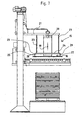
- Fig. 1 1 shows a side view of a device according to the invention for shrinking a heat-shrinkable film jacket 2 placed around a stack of goods 1.
- the stack of goods 1 stands on a pallet 3 on the underside.
- the pallet 3 itself rests on a conveyor 4.
- a bottom foil 5 is first placed, the bottom foil 5 protruding over the edge of the pallet 3.
- the bottom sheet 5 of the stack for example, paper, sold.
- a cover sheet 6 is then placed on the stack 1, whereby the cover sheet 6 over the edge of the stack of goods. 1 survives.
- the cover sheet 6 is cut to length by a continuous film roll. Both the overhanging edge 7 of the bottom foil 5 and the overhanging edge 8 of the cover sheet 6 are folded down.
- a heat shrink film jacket 2 is then placed around the stack 1.
- the stack 1 can be driven for example against a film curtain of a heat shrink film, which extends transversely to the conveying direction.
- the heat shrink film sets around the stack 1 around.
- In the region of the direction of travel opposite side of the so placed around the stack 1 around the heat shrink film jacket 2 is usually welded by a vertically aligned welding bar. In this way, a band is formed, as in Fig. 1 is shown.
- Adjacent to the conveyor 4 is on a frame 11 via a drive 12 in the vertical direction (arrow 13) movable shrink frame 14 consisting of four heating bar 14a for shrinking by heating the heat shrink film jacket 2 is provided.
- This consists in the illustrated embodiment of a parallel to the top of the stack 1 aligned plate 16, wherein the plate 16 projects in the illustrated embodiment about 50 mm on all sides over the contour of the stack 1.
- the plate 16 On the side facing the stack 1, the plate 16 has a coating, for example a Teflon coating, in order to avoid adhesions to the cover sheet 6. Center is in the in the Fig. 1 to 8 illustrated embodiment in the plate 16 is provided a recess 17 for the discharge of hot gases. At these recesses 17, a channel section 18 connects to the upper side, in which a throttle valve 19 and designed as a fan conveyor 20 are provided.
- a coating for example a Teflon coating
- Fig. 8 the design of the combined heat deflection and pressing device 15 is shown in detail.
- the combined is attached to two struts 21, which in turn are connected to the frame 11.
- the struts 21 are fixed against each other.
- rod-shaped holding elements 23 are provided on the underside, at the lower ends of a square frame 24 is attached.
- a square frame 24 is attached in each corner of the frame 24 has an outwardly facing retaining plate 25, each with a bore 26.
- Fig. 8 in connection for example with Fig. 4 can be seen, the plate 16 of the combined choirumlenk- and Anpress adopted 15 at a distance to form a free space 27 from below hung on the frame 24.
- 16 fastening pins 28 are formed with an end-side thickening 29 on the top of the plate.
- Each mounting pin 28 is guided in the associated bore 26, wherein the thickening 29 is greater than the diameter of the bore 26 and is located above the retaining plate 25.
- the mounting pins 28 are moved into the holes 26 and thus the free space 27 is reduced.
- the channel portion 18 is formed accordingly.
- the channel portion 18 is divided into a lower part of the channel portion 18a with a smaller contour and an upper part of the channel portion 18b with a larger contour, so that both partial channel sections 18a, 18b are slidable into each other.
- the special design of the combined heat deflection and pressing device 15 allows a pressing to take place only with the actual weight of the plate 16. Only when the free space has been overcome 27, can also be used with a higher contact pressure, because then in addition to the weight of the remaining parts of the combined michumlenk- and pressing device 15 and the force of the drive 12 acts.
- the shrink frame 14 moves into the in Fig. 2 shown position corresponding to about half the height of the stack 1. Only when reaching this position, the shrink frame 14, which in the Fig. 2 to 7 shown cut, started.
- the hot gases flow in the direction of the arrows 30 up along the sides of the stack of goods 1.
- the conveyor 20 stands on bubbles, so that air is blown in the direction of arrows 31 on the top and so the top projection 9 is erected.
- the throttle valve 19 is in the open position.
- the distance between the heat deflecting and pressing device 15 and the top of the stack 1 is reduced.
- the distance is about 500 mm.
- the distance is reduced to about 200 mm.
- the conveyor 20 is already set to suction, so that along the sides upwardly flowing hot gases (arrows 30) in a direction parallel to the top of the stack 1 direction (arrows 32) are deflected.
- the heat-shrinkable film jacket 2 and the cover sheet film 6 in the region of the upper side is heated sufficiently for a good upper shrinkage.
- the shrink frame 14 has reached its uppermost position. Then, the shrink frame 14 shrinks the sides, especially in the lower portion of the stack 1, move vertically downwards, as it is in Fig. 5 is shown. In this vertical downwards method, the hot gases (arrows 32) are still sucked off via the conveying device 20 through the recess 17 in the direction of the arrows 33.
- the shrink frame 14 has reached its lowermost position for performing the undershrink formation.
- the conveyor 20 is turned off and the throttle valve 19 is closed.
- the combined heat deflection and pressing device 15 is pressed in the direction of the arrow 34 on the top of the stack 1, so that the superposed layers of heat shrink film jacket 2 and cover sheet 6 are connected to each other in the top by pressing the not completely cooled superimposed layers.
- the pressing can also be done earlier.
- the shrink frame 14 and the heat deflection and pressing 15 is again in the in Fig. 7 shifted position shown and transported the wrapped and shrunk stack 1 by means of the conveyor 4.
- FIGS. 9 to 14 is shown a further embodiment of the device according to the invention.
- the heating bar 14a oriented orthogonally to the conveying direction 35 is designed to be movable relative to the remaining shrink frame 14. This allows an adjustment of the distance between the stack 1 on the one hand and the movable heating bar 14a of the shrinking frame 14 designed as a shrinking device. Such movability is offered when goods stack 1 different dimensions, such as length, to be packed.
- Fig. 9 . 10 and 14 is a stack 1 lesser length shown. Therefore, the in the Fig. 9 and 10 shown left heating bar 14a has been moved in the direction of the opposite heating bar 14a in a substantially orthogonal to this side face aligned travel direction 36. In this case, the conveying direction 35 and the direction of travel 36 are the same.
- the heating bar 14a can be moved in two different positions.
- intermediate positions of the displaced heating strip 14a can be controlled.
- FIG Fig. 10 shown position of the heating bar 14a useful when the heating segments are disabled in the end protruding portion X of the heating strips 14a with the top side mounted rails 37.
- the plate 16 has two recesses 17, to each of which a channel portion 18 connects, in each of which a throttle valve 19 and a conveyor 20 designed as a fan are provided.
- only one of the four heating strips 14a is designed to be movable, while the remaining part of the shrink frame 14 consisting of the other three heating strips 14a is not traversable in itself and assumes an overall U-shaped design.
- embodiments are possible in which two or more heating strips 14a are movable, so that both an adaptation to the length and to the width of the stack 1 is possible.
- the stack 1 is at the in the Fig. 9 , 10 and 14 illustrated embodiment placed so that the center of the stack 1 approximately to the center of the right Recess 17 matches.
- the distance on opposite sides of the stack 1 to the respective adjacent and parallel to these sides heating strips 14a is approximately equal. Is it the case in the Fig. 9 and 10 shown good stack 1 is then the left heating bar 14a in the direction of the stack 1 until the distance corresponds approximately to the distance between the other three heating strips 14a and the stack 1.
- both conveyors 20 are "active" and, for example, when sucking both throttle valves 19 are opened, since both recesses 17 are within the contour of the stack 1.
- the stack 1 is placed so that the center between the recesses 17 with the center of the top of the stack 1 is aligned approximately coincident.
- Fig. 12 for a longer stack 1
- Fig. 10 for a shorter stack 1 illustrated operating situation corresponds approximately to in Fig. 2 illustrated operating situation.
- a device 41 is provided. This device 41 is provided in the region of the edge of the plate 16, which projects laterally in comparison to the other edges of the plate 16 with respect to the stack 1 most.
- the device 41 is formed as a cylinder 42 which engages a connected to the plate 16 lever arm 43 and so the plate 16 is raised in the region of this edge.
- the plate does not tilt 16 but is held in an approximately horizontal orientation, so that acts on each point of the top of the stack 1 in about the same force.
- a plurality of heating strips 14a are movable, it makes sense if a device 41 is provided in the region of each edge of the plate 16, to which a movable heating strip 14a adjoins.
Landscapes
- Engineering & Computer Science (AREA)
- Mechanical Engineering (AREA)
- Basic Packing Technique (AREA)
- Labeling Devices (AREA)
- Closing Of Containers (AREA)
- Packages (AREA)
- Laminated Bodies (AREA)
Claims (22)
- Procédé de rétrécissement d'une feuille thermorétractile (2) disposée autour d'une pile de marchandises (1), en particulier en palettes, avec au moins un dispositif de rétrécissement mobile sur un châssis (11) dans le sens vertical (flèche 13), réalisé en particulier comme un cadre de rétrécissement (14) pour le rétrécissement de la feuille thermorétractile (2) par chauffage, dans lequel la feuille thermorétractile (2) dépasse côté supérieur au moins de l'arête supérieure de la pile de marchandises (1) pour la formation du rétrécissement supérieur et une feuille de recouvrement (6) dépassant de préférence du bord de la pile de marchandises (1) est disposée sur le côté supérieur de la pile de marchandises (1), laquelle est soudée à la feuille thermorétractile (2), caractérisé en ce que dans une première étape, les gaz chauds (flèches 30) montant le long des côtés de la pile de marchandises (1) sont déviés vers l'intérieur par un dispositif de déviation thermique et de pressage (15) combiné disposé au-dessus de la pile de marchandises (1) pour le préchauffage et le déplacement vers l'intérieur de la saillie (9) de la feuille thermorétractile (2) et pour le préchauffage de la feuille de recouvrement (6) dans la zone du côté supérieur de la pile de marchandises (1) dans un sens (flèches 32) s'étendant au moins à peu près parallèlement au côté supérieur de la pile de marchandises (1) et dans une seconde étape, les couches reposant désormais l'une sur l'autre de la saillie (9) déplacée de la feuille thermorétractile (2) et de la feuille de recouvrement (6) sont reliées au moins dans la zone du côté supérieur de la pile de marchandises (1) par pressage l'une sur l'autre des couches reposant l'une sur l'autre, pas encore totalement refroidies de la feuille thermorétractile (2) et de la feuille de recouvrement (6) au moyen du dispositif de déviation thermique et de pressage (15) combiné.
- Procédé selon la revendication précédente, caractérisé en ce que pour le rétrécissement, le dispositif de rétrécissement est déplacé tout d'abord pour la réalisation du rétrécissement supérieur vers le haut puis pour la réalisation du rétrécissement inférieur vers le bas.
- Procédé selon la revendication précédente, caractérisé en ce que le rétrécissement commence environ à mi-hauteur de la pile de marchandises (1).
- Procédé selon l'une quelconque des revendications précédentes, caractérisé en ce qu'au moins au début du processus de rétrécissement, la saillie (9) dépassant côté supérieur de l'arête supérieure de la pile de marchandises (1) de la feuille thermorétractile (2) est redressée en particulier au moyen d'un courant d'air (flèches 31) dirigé directement ou indirectement vers l'extérieur, généré par le dispositif de déviation thermique et de pressage (15) combiné.
- Procédé selon l'une quelconque des revendications précédentes, caractérisé en ce que les gaz chauds montant le long des côtés de la pile de marchandises (1) (flèches 30) et déviés dans un sens (flèches 32) s'étendant parallèlement au côté supérieur de la pile de marchandises (1), sont aspirés en particulier au moyen du dispositif de déviation thermique et de pressage (15) combiné.
- Procédé selon l'une quelconque des revendications précédentes, caractérisé en ce qu'au moins pour le déplacement vertical (flèches 13) vers le bas du dispositif de rétrécissement, les couches reposant l'une sur l'autre de la feuille thermorétractile (2) et de la feuille de recouvrement (6) sont reliées au moins dans la zone du côté supérieur de la pile de marchandises (1) par pressage des couches reposant l'une sur l'autre, pas encore totalement refroidies de la feuille thermorétractile (2) et de la feuille de recouvrement (6).
- Procédé selon l'une quelconque des revendications 1 à 6, caractérisé en ce qu'au moins lors de la réalisation du rétrécissement inférieur, les couches reposant l'une sur l'autre de la feuille thermorétractile (2) et de la feuille de recouvrement (6) sont reliées au moins dans la zone du côté supérieur de la pile de marchandises (1) par pressage des couches reposant l'une sur l'autre, pas encore totalement refroidies de la feuille thermorétractile (2) et de la feuille de recouvrement (6).
- Dispositif de rétrécissement d'une feuille thermorétractile (2) disposée autour d'une pile de marchandises (1), en particulier en palettes, avec au moins un dispositif de rétrécissement mobile sur un châssis (11) dans le sens vertical (flèche 13), réalisé en particulier comme un cadre de rétrécissement (14) pour le rétrécissement de la feuille thermorétractile (2) par chauffage, dans lequel la feuille thermorétractile (2) dépasse côté supérieur au moins de l'arête supérieure de la pile de marchandises (1) pour la formation du rétrécissement supérieur et une feuille de recouvrement (6) dépassant de préférence du bord de la pile de marchandises (1) est disposée sur le côté supérieur de la pile de marchandises (1), laquelle peut être soudée à la feuille thermorétractile (2), en particulier pour la réalisation d'un procédé selon les revendications 1 à 7, caractérisé en ce qu'un dispositif de déviation thermique et de pressage (15) combiné est disposé au-dessus de la pile de marchandises (1), d'une part pour la déviation des gaz chauds (flèche 30) montant le long des côtés de la pile de marchandises (1) dans un sens (flèches 32) s'étendant au moins à peu près parallèlement au côté supérieur de la pile de marchandises (1) pour un préchauffage et pour un déplacement vers l'intérieur de la saillie (9) de la feuille thermorétractile (2) et pour un préchauffage de la feuille de recouvrement (6) dans la zone du côté supérieur de la pile de marchandises (1), et d'autre part pour la liaison consécutive de la saillie (9) déplacée de la feuille thermorétractile (2) et de la feuille de recouvrement (6) au moins dans la zone du côté supérieur de la pile de marchandises (1) par pressage l'une sur l'autre des couches reposant l'une sur l'autre, pas encore totalement refroidies de la feuille thermorétractile (2) et de la feuille de recouvrement (6).
- Dispositif selon la revendication 8, caractérisé en ce qu'une plaque (16) orientée parallèlement au côté supérieur de la pile de marchandises (1) est prévue comme dispositif de déviation thermique et de pressage (15) combiné.
- Dispositif selon la revendication 9, caractérisé en ce que la plaque (16) présente sur le côté tourné vers la pile de marchandises (1) un revêtement, de préférence un revêtement en téflon.
- Dispositif selon l'une quelconque des revendications 8 à 10, caractérisé en ce que les arêtes du dispositif de déviation thermique et de pressage (15) combiné s'alignent à peu près avec les côtés de la pile de marchandises (1).
- Dispositif selon l'une quelconque des revendications 8 à 11, caractérisé en ce que le dispositif de déviation thermique et de pressage (15) combiné dépasse latéralement du contour de la pile de marchandises (1).
- Dispositif selon l'une quelconque des revendications 8 à 12, caractérisé en ce que le dispositif de déviation thermique et de pressage (15) combiné présente vers le haut (flèches 33) au moins un évidement (17) disposé de préférence à peu près au milieu du dispositif de déviation thermique et de pressage (15) combiné pour la sortie des gaz chauds passant parallèlement au côté supérieur (flèches 32) de la pile de marchandises (1) en direction du milieu.
- Dispositif selon la revendication 13, caractérisé en ce que la position d'au moins un évidement (17) pour la modification du point, dans lequel les gaz chauds passant tout d'abord parallèlement au côté supérieur de la pile de marchandises (1) en direction des flèches (32) sont déviés vers le haut en direction des flèches (33), peut être modifiée.
- Dispositif selon la revendication 13 ou 14, caractérisé en ce qu'un dispositif de transport (20) est prévu pour l'aspiration des gaz chauds passant parallèlement au côté supérieur de la pile de marchandises (1) en direction (flèches 32) du milieu au-dessus d'au moins un évidement (17).
- Dispositif selon l'une quelconque des revendications 13 à 15, caractérisé en ce qu'un clapet d'étranglement (19) est prévu dans la zone d'au moins un évidement (17).
- Dispositif selon la revendication précédente, caractérisé en ce qu'au moins la zone pouvant être amenée en contact avec les couches reposant l'une sur l'autre, pas encore totalement refroidies de la feuille thermorétractile (2) et de la feuille de recouvrement (6) du dispositif de déviation thermique et de pressage (15) combiné peut être refroidie.
- Dispositif selon l'une quelconque des revendications 8 à 17, caractérisé en ce que pour une adaptation de la distance entre la pile de marchandises (1) d'une part et au moins une barre de chauffage (14a) s'étendant essentiellement parallèlement à la surface latérale correspondante de la pile de marchandises (1) du cadre de refroidissement (14) réalisé comme un dispositif de rétrécissement d'autre part, au moins une barre de chauffage (14a) peut être modifiée dans sa position par déplacement dans un sens de déplacement (36) orienté essentiellement perpendiculairement à cette surface latérale.
- Dispositif selon la revendication 18, caractérisé en ce qu'au moins l'une des deux barres de chauffage (14a) s'étendant essentiellement perpendiculairement au sens de transport (35) de la pile de marchandises (1) pour l'adaptation de la distance entre la pile de marchandises (1) d'une part et au moins l'une des deux barres de chauffage (14a) s'étendant essentiellement perpendiculairement au sens de transport (35) de la pile de marchandises (1) peut être modifiée dans sa position par déplacement.
- Dispositif selon la revendication 18 et 19, caractérisé en ce que la barre de chauffage (14a) mobile par rapport au cadre de rétrécissement (14) restant est disposée sur au moins un rail (37) prévu sur le cadre de rétrécissement (14a) restant et un entraînement est prévu pour un déplacement.
- Dispositif selon l'une quelconque des revendications 8 à 20, caractérisé en ce qu'un dispositif (41) est prévu, lequel empêche un basculement du dispositif de déviation thermique et de pressage (15) combiné, en particulier à l'état reposant sur le côté supérieur de la pile de marchandises (1).
- Dispositif selon l'une quelconque des revendications 18 à 21, caractérisé en ce qu'au moins une barre de chauffage (14a) se compose de plusieurs segments de chauffage, de préférence de plusieurs segments de chauffage activables séparément.
Priority Applications (1)
| Application Number | Priority Date | Filing Date | Title |
|---|---|---|---|
| PL06806469T PL1940686T3 (pl) | 2005-10-24 | 2006-10-23 | Sposób i urządzenie do obkurczania folii termokurczliwej układanej wokół, zwłaszcza paletyzowanego, stosu towarów |
Applications Claiming Priority (3)
| Application Number | Priority Date | Filing Date | Title |
|---|---|---|---|
| DE202005016725 | 2005-10-24 | ||
| DE202005020192U DE202005020192U1 (de) | 2005-10-24 | 2005-12-24 | Vorrichtung zum Schrumpfen einer um einen, insbesondere palettierten, Gutstapel gelegten Heißschrumpffolie |
| PCT/EP2006/010198 WO2007048558A1 (fr) | 2005-10-24 | 2006-10-23 | Procédé et dispositif de rétrécissement d’une feuille thermorétractile disposée autour d’une pile de marchandises, en particulier en palettes |
Publications (2)
| Publication Number | Publication Date |
|---|---|
| EP1940686A1 EP1940686A1 (fr) | 2008-07-09 |
| EP1940686B1 true EP1940686B1 (fr) | 2009-06-03 |
Family
ID=36580598
Family Applications (1)
| Application Number | Title | Priority Date | Filing Date |
|---|---|---|---|
| EP06806469A Active EP1940686B1 (fr) | 2005-10-24 | 2006-10-23 | Procédé et dispositif de rétrécissement d une feuille thermorétractile disposée autour d une pile de marchandises, en particulier en palettes |
Country Status (10)
| Country | Link |
|---|---|
| US (1) | US7703263B2 (fr) |
| EP (1) | EP1940686B1 (fr) |
| AT (1) | ATE432876T1 (fr) |
| BR (1) | BRPI0617755B1 (fr) |
| CA (1) | CA2626566C (fr) |
| DE (2) | DE202005020192U1 (fr) |
| ES (1) | ES2328281T3 (fr) |
| PL (1) | PL1940686T3 (fr) |
| PT (1) | PT1940686E (fr) |
| WO (1) | WO2007048558A1 (fr) |
Cited By (1)
| Publication number | Priority date | Publication date | Assignee | Title |
|---|---|---|---|---|
| EP2639166A1 (fr) * | 2012-03-12 | 2013-09-18 | MSK - Verpackungs-Systeme GmbH | Dispositif et procédé destinés à emmancher une feuille d'emballage sur une pile de marchandises |
Families Citing this family (14)
| Publication number | Priority date | Publication date | Assignee | Title |
|---|---|---|---|---|
| DE102007015753B4 (de) * | 2007-03-30 | 2018-08-09 | Khs Gmbh | Schrumpftunnel, Schrumpfgaserhitzer und Verfahren zum Aufschrumpfen von Schrumpffolien auf Verpackungen oder Verpackungseinheiten |
| CN102149768B (zh) * | 2008-07-15 | 2016-01-20 | 陶氏环球技术有限责任公司 | 交联膜以及由该交联膜制备的制品 |
| IT1400702B1 (it) * | 2010-06-23 | 2013-06-28 | Marpak Oms Group S R L | Apparecchiatura per l'imballaggio di carichi con pellicola termoretraibile, dotata di bruciatori regolabili. |
| DE102010031800A1 (de) | 2010-07-20 | 2012-01-26 | Krones Aktiengesellschaft | Anordnung und Verfahren zur Koppelung mehrerer Maschinenbaugruppen einer Behälterbehandlungsmaschine |
| KR101187743B1 (ko) * | 2010-11-11 | 2012-10-04 | (주)아이피에스코리아 | 열수축 필름 포장장치 |
| EP2740673B1 (fr) * | 2012-12-06 | 2015-07-08 | MSK - Verpackungs-Systeme GmbH | Procédé et dispositif d'application d'une feuille sur une pile de marchandises |
| KR101559989B1 (ko) * | 2013-08-13 | 2015-10-14 | 더블유아이씨 주식회사 | 반도체 제조용 특수가스통의 포장을 위한 비닐 수축장치 |
| DK3147226T3 (da) * | 2015-09-23 | 2018-10-15 | Msk Verpackung Syst Gmbh | Fremgangsmåde til dannelse af et frirum i en emballage, der består af krympefolie, og som sikrer en godsstabel på en palle, såvel som en formeindretning til realisering af fremgangsmåden |
| DE102016212436B4 (de) * | 2016-07-07 | 2018-07-26 | Signode Industrial Group Llc | Verpackungsverfahren und Haubenstretchanlage |
| EP3381816B1 (fr) * | 2017-03-28 | 2021-02-24 | MSK - Verpackungs-Systeme GmbH | Procédé de création d'au moins un espace libre dans une enveloppe comprenant une feuille étirable, qui immobilise une pile de produits disposés sur une palette et dispositif de façonnage destiné à exécuter le procédé |
| CN106976602A (zh) * | 2017-05-31 | 2017-07-25 | 江苏中大包装材料有限公司 | 一种收缩膜加热机构 |
| CN114476255A (zh) * | 2022-02-11 | 2022-05-13 | 曾荣金 | 一种砂轮盘智能化套热缩膜的辅助设备 |
| CN117864536A (zh) * | 2024-03-07 | 2024-04-12 | 常州福斯智能科技有限公司 | 一种车灯驱动控制器加工用包装设备的使用方法 |
| CN121084720B (zh) * | 2025-11-07 | 2026-01-09 | 常州市天方印刷有限公司 | 一种附带质量反馈功能的全自动打包装置 |
Family Cites Families (14)
| Publication number | Priority date | Publication date | Assignee | Title |
|---|---|---|---|---|
| US3662512A (en) * | 1968-01-24 | 1972-05-16 | Weldotron Corp | Method and apparatus for shrink-film wrapping a pallet load |
| DE6801652U (de) * | 1968-10-10 | 1969-01-23 | Nuetro Hirsch & Co | Vorrichtung zum verpacken von stueckguetern auf einem grundrahmen |
| US3807126A (en) * | 1970-06-10 | 1974-04-30 | Schwartz F Gmbh Ind Und Maschi | Wrapping and securing loads on pallets |
| US3667598A (en) * | 1971-02-18 | 1972-06-06 | Weldotron Corp | Wrapped pallet load |
| US3930790A (en) * | 1971-04-08 | 1976-01-06 | Ethyl Corporation | Method and apparatus for shrinking plastic film over grouped articles |
| FR2181141A5 (fr) * | 1972-04-18 | 1973-11-30 | Lucas Jean Louis | |
| DE8513892U1 (de) * | 1985-05-10 | 1985-09-05 | MSK - Verpackungs-Systeme GmbH, 4190 Kleve | Vorrichtung zum Überziehen und Einschrumpfen von Gutstapeln mit Schrumpfhauben |
| DE8708145U1 (de) * | 1987-06-06 | 1987-08-06 | MSK-Verpackungs-Systeme GmbH, 4190 Kleve | Vorrichtung zum Schrumpfen von Schrumpfhauben, die einen palettierten Gutstapel umgeben |
| IT1255924B (it) | 1992-10-28 | 1995-11-17 | Sestese Off Mec | Apparecchiatura a getti di aria calda, per l'imballaggio di materiale accatastato su pallets con pellicola di materiale plastico termoretraibile. |
| DE4423513C1 (de) * | 1993-10-26 | 1996-02-01 | Moellers Maschf Gmbh | Vorrichtung zum Einschrumpfen einer Schrumpffolienhaube |
| FR2723564B1 (fr) * | 1994-08-12 | 1996-09-20 | Newtec Int | Procede et dispositif de suremballage, par thermo-retraction, d'une charge palettisee |
| CN1174898C (zh) * | 1999-01-28 | 2004-11-10 | Msk包装系统股份有限公司 | 使热收缩薄膜产生收缩的装置 |
| FI991020A0 (fi) * | 1999-05-04 | 1999-05-04 | United Packaging Plc | Käärintäpakkausmenetelmä ja käärintäpakkauskone |
| FR2855814B1 (fr) | 2003-06-06 | 2005-08-19 | Thimon | Procede et dispositif d'emballage d'une charge par un film souple thermoretractable |
-
2005
- 2005-12-24 DE DE202005020192U patent/DE202005020192U1/de not_active Expired - Lifetime
-
2006
- 2006-10-23 DE DE502006003909T patent/DE502006003909D1/de active Active
- 2006-10-23 US US12/090,104 patent/US7703263B2/en active Active
- 2006-10-23 PT PT06806469T patent/PT1940686E/pt unknown
- 2006-10-23 CA CA2626566A patent/CA2626566C/fr not_active Expired - Fee Related
- 2006-10-23 WO PCT/EP2006/010198 patent/WO2007048558A1/fr not_active Ceased
- 2006-10-23 AT AT06806469T patent/ATE432876T1/de active
- 2006-10-23 EP EP06806469A patent/EP1940686B1/fr active Active
- 2006-10-23 BR BRPI0617755-7A patent/BRPI0617755B1/pt not_active IP Right Cessation
- 2006-10-23 ES ES06806469T patent/ES2328281T3/es active Active
- 2006-10-23 PL PL06806469T patent/PL1940686T3/pl unknown
Cited By (4)
| Publication number | Priority date | Publication date | Assignee | Title |
|---|---|---|---|---|
| EP2639166A1 (fr) * | 2012-03-12 | 2013-09-18 | MSK - Verpackungs-Systeme GmbH | Dispositif et procédé destinés à emmancher une feuille d'emballage sur une pile de marchandises |
| WO2013135634A1 (fr) * | 2012-03-12 | 2013-09-19 | Msk - Verpackungs-Systeme Gmbh | Dispositif et procédé de rétrécissement d'un film rétractable sur une pile de produits |
| CN104203755A (zh) * | 2012-03-12 | 2014-12-10 | Msk包装系统有限公司 | 用于将收缩薄膜紧缩到物品堆上的设备和方法 |
| CN104203755B (zh) * | 2012-03-12 | 2016-10-26 | Msk包装系统有限公司 | 用于将收缩薄膜紧缩到物品堆上的设备和方法 |
Also Published As
| Publication number | Publication date |
|---|---|
| WO2007048558A1 (fr) | 2007-05-03 |
| US20080202072A1 (en) | 2008-08-28 |
| PT1940686E (pt) | 2009-08-24 |
| BRPI0617755B1 (pt) | 2018-07-03 |
| ATE432876T1 (de) | 2009-06-15 |
| EP1940686A1 (fr) | 2008-07-09 |
| DE202005020192U1 (de) | 2006-05-24 |
| PL1940686T3 (pl) | 2009-12-31 |
| ES2328281T3 (es) | 2009-11-11 |
| CA2626566C (fr) | 2014-07-29 |
| BRPI0617755A2 (pt) | 2011-08-02 |
| US7703263B2 (en) | 2010-04-27 |
| DE502006003909D1 (de) | 2009-07-16 |
| CA2626566A1 (fr) | 2007-05-03 |
Similar Documents
| Publication | Publication Date | Title |
|---|---|---|
| EP1940686B1 (fr) | Procédé et dispositif de rétrécissement d une feuille thermorétractile disposée autour d une pile de marchandises, en particulier en palettes | |
| EP0344815B2 (fr) | Procédé et dispositif pour envelopper des marchandises, en particulier des piles de marchandises avec une housse de film étirable | |
| DE4103384C2 (de) | Vorrichtung zum Überziehen von Stretchfolienhauben über einen Gutstapel | |
| EP0077508B1 (fr) | Procédé et dispositif d'emballage de piles d'objets palettisés | |
| EP1000858B1 (fr) | Proçédé et dispositif pour appliquer et rétracter une housse d'emballage sur un objet | |
| DE3242677C2 (fr) | ||
| DE2440517A1 (de) | Verfahren und vorrichtung zum einhuellen einer last auf einer palette | |
| EP1361980B1 (fr) | Dispositif et procede pour ajouter des saillies de film | |
| EP3381816B1 (fr) | Procédé de création d'au moins un espace libre dans une enveloppe comprenant une feuille étirable, qui immobilise une pile de produits disposés sur une palette et dispositif de façonnage destiné à exécuter le procédé | |
| EP3672875B1 (fr) | Dispositif d'emballage et procédé destiné à emballer des objets | |
| EP1050466A1 (fr) | Procede et appareil pour emballer des articles dans un film retractable | |
| EP1147050A1 (fr) | Dispositif pour contracter un film thermo-retrecissable | |
| EP3070009A1 (fr) | Dispositif et procede de fabrication de gerbes de film retractable | |
| EP3147226B1 (fr) | Procede de fabrication d'au moins un espace libre dans une enveloppe constituee de feuille retractable, bloquant une pile de marchandises disposee sur une palette, et dispositif de formage destine a l'execution du procede | |
| DE3908957A1 (de) | Verfahren und vorrichtung zum umhuellen von stueckgut mit kunststoffolie | |
| EP0378730B1 (fr) | Appareil pour emballer des objets avec une bande tubulaire en matière plastique | |
| DE3924577B4 (de) | Verfahren und Vorrichtung zum Verpacken von Gegenständen mit einer schlauchförmigen Kunststoffolie | |
| EP2771630B1 (fr) | Dispositif de refroidissement | |
| EP0460681B1 (fr) | Installation pour plier en accordéon et/ou étirer une gaine tubulaire d'emballage étirable | |
| EP3214003B1 (fr) | Procede et dispositif de retraction d'une feuille thermoretractable disposee autour d'une pile de marchandises, notamment palettisee | |
| DE102004001301B4 (de) | Verpackungsvorrichtung zum Verpacken von Paletten | |
| DE19503927A1 (de) | Verfahren und Vorrichtung zum Überziehen einer Stretchfolienhaube über einen Gutstapel | |
| EP0933297A1 (fr) | Procédé et dispositif pour emballer une charge | |
| EP4119451B1 (fr) | Procédé de création d'au moins une zone libre dans une enveloppe composée d'une feuille rétractable, de préférence conçue sous la forme de capot rétractable et dispositif de formage destiné à la mise en uvre d'un procédé de création d'au moins une zone libre dans une enveloppe composée d'une feuille rétractable, de préférence conçue sous la forme de capot rétractable | |
| EP1350720B1 (fr) | Procédé et appareil pour emballer une pile d'objets |
Legal Events
| Date | Code | Title | Description |
|---|---|---|---|
| PUAI | Public reference made under article 153(3) epc to a published international application that has entered the european phase |
Free format text: ORIGINAL CODE: 0009012 |
|
| 17P | Request for examination filed |
Effective date: 20080422 |
|
| AK | Designated contracting states |
Kind code of ref document: A1 Designated state(s): AT BE BG CH CY CZ DE DK EE ES FI FR GB GR HU IE IS IT LI LT LU LV MC NL PL PT RO SE SI SK TR |
|
| GRAP | Despatch of communication of intention to grant a patent |
Free format text: ORIGINAL CODE: EPIDOSNIGR1 |
|
| GRAS | Grant fee paid |
Free format text: ORIGINAL CODE: EPIDOSNIGR3 |
|
| GRAA | (expected) grant |
Free format text: ORIGINAL CODE: 0009210 |
|
| AK | Designated contracting states |
Kind code of ref document: B1 Designated state(s): AT BE BG CH CY CZ DE DK EE ES FI FR GB GR HU IE IS IT LI LT LU LV MC NL PL PT RO SE SI SK TR |
|
| REG | Reference to a national code |
Ref country code: GB Ref legal event code: FG4D Free format text: NOT ENGLISH |
|
| REG | Reference to a national code |
Ref country code: CH Ref legal event code: EP |
|
| REG | Reference to a national code |
Ref country code: IE Ref legal event code: FG4D Free format text: LANGUAGE OF EP DOCUMENT: GERMAN |
|
| REF | Corresponds to: |
Ref document number: 502006003909 Country of ref document: DE Date of ref document: 20090716 Kind code of ref document: P |
|
| REG | Reference to a national code |
Ref country code: PT Ref legal event code: SC4A Free format text: AVAILABILITY OF NATIONAL TRANSLATION Effective date: 20090818 |
|
| PG25 | Lapsed in a contracting state [announced via postgrant information from national office to epo] |
Ref country code: LT Free format text: LAPSE BECAUSE OF FAILURE TO SUBMIT A TRANSLATION OF THE DESCRIPTION OR TO PAY THE FEE WITHIN THE PRESCRIBED TIME-LIMIT Effective date: 20090603 |
|
| NLV1 | Nl: lapsed or annulled due to failure to fulfill the requirements of art. 29p and 29m of the patents act | ||
| REG | Reference to a national code |
Ref country code: ES Ref legal event code: FG2A Ref document number: 2328281 Country of ref document: ES Kind code of ref document: T3 |
|
| PG25 | Lapsed in a contracting state [announced via postgrant information from national office to epo] |
Ref country code: SE Free format text: LAPSE BECAUSE OF FAILURE TO SUBMIT A TRANSLATION OF THE DESCRIPTION OR TO PAY THE FEE WITHIN THE PRESCRIBED TIME-LIMIT Effective date: 20090903 Ref country code: NL Free format text: LAPSE BECAUSE OF FAILURE TO SUBMIT A TRANSLATION OF THE DESCRIPTION OR TO PAY THE FEE WITHIN THE PRESCRIBED TIME-LIMIT Effective date: 20090603 Ref country code: LV Free format text: LAPSE BECAUSE OF FAILURE TO SUBMIT A TRANSLATION OF THE DESCRIPTION OR TO PAY THE FEE WITHIN THE PRESCRIBED TIME-LIMIT Effective date: 20090603 Ref country code: SI Free format text: LAPSE BECAUSE OF FAILURE TO SUBMIT A TRANSLATION OF THE DESCRIPTION OR TO PAY THE FEE WITHIN THE PRESCRIBED TIME-LIMIT Effective date: 20090603 |
|
| REG | Reference to a national code |
Ref country code: SE Ref legal event code: TRGR |
|
| REG | Reference to a national code |
Ref country code: PL Ref legal event code: T3 |
|
| REG | Reference to a national code |
Ref country code: IE Ref legal event code: FD4D |
|
| PG25 | Lapsed in a contracting state [announced via postgrant information from national office to epo] |
Ref country code: IE Free format text: LAPSE BECAUSE OF FAILURE TO SUBMIT A TRANSLATION OF THE DESCRIPTION OR TO PAY THE FEE WITHIN THE PRESCRIBED TIME-LIMIT Effective date: 20090603 Ref country code: EE Free format text: LAPSE BECAUSE OF FAILURE TO SUBMIT A TRANSLATION OF THE DESCRIPTION OR TO PAY THE FEE WITHIN THE PRESCRIBED TIME-LIMIT Effective date: 20090603 Ref country code: CZ Free format text: LAPSE BECAUSE OF FAILURE TO SUBMIT A TRANSLATION OF THE DESCRIPTION OR TO PAY THE FEE WITHIN THE PRESCRIBED TIME-LIMIT Effective date: 20090603 Ref country code: RO Free format text: LAPSE BECAUSE OF FAILURE TO SUBMIT A TRANSLATION OF THE DESCRIPTION OR TO PAY THE FEE WITHIN THE PRESCRIBED TIME-LIMIT Effective date: 20090603 Ref country code: IS Free format text: LAPSE BECAUSE OF FAILURE TO SUBMIT A TRANSLATION OF THE DESCRIPTION OR TO PAY THE FEE WITHIN THE PRESCRIBED TIME-LIMIT Effective date: 20091003 |
|
| PG25 | Lapsed in a contracting state [announced via postgrant information from national office to epo] |
Ref country code: SK Free format text: LAPSE BECAUSE OF FAILURE TO SUBMIT A TRANSLATION OF THE DESCRIPTION OR TO PAY THE FEE WITHIN THE PRESCRIBED TIME-LIMIT Effective date: 20090603 |
|
| PG25 | Lapsed in a contracting state [announced via postgrant information from national office to epo] |
Ref country code: BG Free format text: LAPSE BECAUSE OF FAILURE TO SUBMIT A TRANSLATION OF THE DESCRIPTION OR TO PAY THE FEE WITHIN THE PRESCRIBED TIME-LIMIT Effective date: 20090903 |
|
| PLBE | No opposition filed within time limit |
Free format text: ORIGINAL CODE: 0009261 |
|
| STAA | Information on the status of an ep patent application or granted ep patent |
Free format text: STATUS: NO OPPOSITION FILED WITHIN TIME LIMIT |
|
| BERE | Be: lapsed |
Owner name: MSK-VERPACKUNGS-SYSTEME G.- MIT BESCHRANKTER HAFT Effective date: 20091031 |
|
| PG25 | Lapsed in a contracting state [announced via postgrant information from national office to epo] |
Ref country code: DK Free format text: LAPSE BECAUSE OF FAILURE TO SUBMIT A TRANSLATION OF THE DESCRIPTION OR TO PAY THE FEE WITHIN THE PRESCRIBED TIME-LIMIT Effective date: 20090603 |
|
| 26N | No opposition filed |
Effective date: 20100304 |
|
| PG25 | Lapsed in a contracting state [announced via postgrant information from national office to epo] |
Ref country code: MC Free format text: LAPSE BECAUSE OF NON-PAYMENT OF DUE FEES Effective date: 20091031 |
|
| PG25 | Lapsed in a contracting state [announced via postgrant information from national office to epo] |
Ref country code: GR Free format text: LAPSE BECAUSE OF FAILURE TO SUBMIT A TRANSLATION OF THE DESCRIPTION OR TO PAY THE FEE WITHIN THE PRESCRIBED TIME-LIMIT Effective date: 20090904 Ref country code: BE Free format text: LAPSE BECAUSE OF NON-PAYMENT OF DUE FEES Effective date: 20091031 |
|
| PG25 | Lapsed in a contracting state [announced via postgrant information from national office to epo] |
Ref country code: LU Free format text: LAPSE BECAUSE OF NON-PAYMENT OF DUE FEES Effective date: 20091023 |
|
| REG | Reference to a national code |
Ref country code: CH Ref legal event code: PL |
|
| GBPC | Gb: european patent ceased through non-payment of renewal fee |
Effective date: 20101023 |
|
| PG25 | Lapsed in a contracting state [announced via postgrant information from national office to epo] |
Ref country code: HU Free format text: LAPSE BECAUSE OF FAILURE TO SUBMIT A TRANSLATION OF THE DESCRIPTION OR TO PAY THE FEE WITHIN THE PRESCRIBED TIME-LIMIT Effective date: 20091204 |
|
| PG25 | Lapsed in a contracting state [announced via postgrant information from national office to epo] |
Ref country code: CH Free format text: LAPSE BECAUSE OF NON-PAYMENT OF DUE FEES Effective date: 20101031 Ref country code: LI Free format text: LAPSE BECAUSE OF NON-PAYMENT OF DUE FEES Effective date: 20101031 |
|
| PG25 | Lapsed in a contracting state [announced via postgrant information from national office to epo] |
Ref country code: GB Free format text: LAPSE BECAUSE OF NON-PAYMENT OF DUE FEES Effective date: 20101023 |
|
| PG25 | Lapsed in a contracting state [announced via postgrant information from national office to epo] |
Ref country code: CY Free format text: LAPSE BECAUSE OF FAILURE TO SUBMIT A TRANSLATION OF THE DESCRIPTION OR TO PAY THE FEE WITHIN THE PRESCRIBED TIME-LIMIT Effective date: 20090603 |
|
| PGRI | Patent reinstated in contracting state [announced from national office to epo] |
Ref country code: SE Effective date: 20091112 |
|
| REG | Reference to a national code |
Ref country code: FR Ref legal event code: PLFP Year of fee payment: 10 |
|
| REG | Reference to a national code |
Ref country code: FR Ref legal event code: PLFP Year of fee payment: 11 |
|
| REG | Reference to a national code |
Ref country code: FR Ref legal event code: PLFP Year of fee payment: 12 |
|
| PGFP | Annual fee paid to national office [announced via postgrant information from national office to epo] |
Ref country code: PL Payment date: 20170922 Year of fee payment: 12 |
|
| PGFP | Annual fee paid to national office [announced via postgrant information from national office to epo] |
Ref country code: ES Payment date: 20171103 Year of fee payment: 12 Ref country code: PT Payment date: 20171016 Year of fee payment: 12 |
|
| REG | Reference to a national code |
Ref country code: FR Ref legal event code: PLFP Year of fee payment: 13 |
|
| PGFP | Annual fee paid to national office [announced via postgrant information from national office to epo] |
Ref country code: IE Payment date: 20181210 Year of fee payment: 13 Ref country code: FI Payment date: 20181019 Year of fee payment: 13 Ref country code: SE Payment date: 20181025 Year of fee payment: 13 |
|
| PGFP | Annual fee paid to national office [announced via postgrant information from national office to epo] |
Ref country code: TR Payment date: 20181015 Year of fee payment: 13 |
|
| PG25 | Lapsed in a contracting state [announced via postgrant information from national office to epo] |
Ref country code: PT Free format text: LAPSE BECAUSE OF NON-PAYMENT OF DUE FEES Effective date: 20190423 |
|
| REG | Reference to a national code |
Ref country code: ES Ref legal event code: FD2A Effective date: 20191203 |
|
| PG25 | Lapsed in a contracting state [announced via postgrant information from national office to epo] |
Ref country code: PL Free format text: LAPSE BECAUSE OF NON-PAYMENT OF DUE FEES Effective date: 20181023 Ref country code: ES Free format text: LAPSE BECAUSE OF NON-PAYMENT OF DUE FEES Effective date: 20181024 |
|
| REG | Reference to a national code |
Ref country code: FI Ref legal event code: MAE |
|
| PG25 | Lapsed in a contracting state [announced via postgrant information from national office to epo] |
Ref country code: FI Free format text: LAPSE BECAUSE OF NON-PAYMENT OF DUE FEES Effective date: 20191023 |
|
| REG | Reference to a national code |
Ref country code: AT Ref legal event code: MM01 Ref document number: 432876 Country of ref document: AT Kind code of ref document: T Effective date: 20191023 |
|
| PG25 | Lapsed in a contracting state [announced via postgrant information from national office to epo] |
Ref country code: SE Free format text: LAPSE BECAUSE OF FAILURE TO SUBMIT A TRANSLATION OF THE DESCRIPTION OR TO PAY THE FEE WITHIN THE PRESCRIBED TIME-LIMIT Effective date: 20191024 |
|
| PG25 | Lapsed in a contracting state [announced via postgrant information from national office to epo] |
Ref country code: AT Free format text: LAPSE BECAUSE OF NON-PAYMENT OF DUE FEES Effective date: 20191023 |
|
| PG25 | Lapsed in a contracting state [announced via postgrant information from national office to epo] |
Ref country code: TR Free format text: LAPSE BECAUSE OF NON-PAYMENT OF DUE FEES Effective date: 20191023 |
|
| P01 | Opt-out of the competence of the unified patent court (upc) registered |
Effective date: 20230509 |
|
| PGFP | Annual fee paid to national office [announced via postgrant information from national office to epo] |
Ref country code: DE Payment date: 20251030 Year of fee payment: 20 |
|
| PGFP | Annual fee paid to national office [announced via postgrant information from national office to epo] |
Ref country code: IT Payment date: 20251031 Year of fee payment: 20 |
|
| PGFP | Annual fee paid to national office [announced via postgrant information from national office to epo] |
Ref country code: FR Payment date: 20251024 Year of fee payment: 20 |