EP1050495A2 - Système de transport de pièces - Google Patents
Système de transport de pièces Download PDFInfo
- Publication number
- EP1050495A2 EP1050495A2 EP00301939A EP00301939A EP1050495A2 EP 1050495 A2 EP1050495 A2 EP 1050495A2 EP 00301939 A EP00301939 A EP 00301939A EP 00301939 A EP00301939 A EP 00301939A EP 1050495 A2 EP1050495 A2 EP 1050495A2
- Authority
- EP
- European Patent Office
- Prior art keywords
- frame
- work piece
- movement
- carrier
- work pieces
- Prior art date
- Legal status (The legal status is an assumption and is not a legal conclusion. Google has not performed a legal analysis and makes no representation as to the accuracy of the status listed.)
- Withdrawn
Links
- 230000007246 mechanism Effects 0.000 claims abstract description 98
- 230000000712 assembly Effects 0.000 claims description 6
- 238000000429 assembly Methods 0.000 claims description 6
- 238000004804 winding Methods 0.000 claims description 2
- 230000000452 restraining effect Effects 0.000 abstract 1
- 238000001035 drying Methods 0.000 description 13
- 238000007747 plating Methods 0.000 description 2
- 229910000746 Structural steel Inorganic materials 0.000 description 1
- 238000010276 construction Methods 0.000 description 1
- 238000007598 dipping method Methods 0.000 description 1
- 239000012634 fragment Substances 0.000 description 1
- 238000010422 painting Methods 0.000 description 1
Images


Classifications
-
- B—PERFORMING OPERATIONS; TRANSPORTING
- B65—CONVEYING; PACKING; STORING; HANDLING THIN OR FILAMENTARY MATERIAL
- B65G—TRANSPORT OR STORAGE DEVICES, e.g. CONVEYORS FOR LOADING OR TIPPING, SHOP CONVEYOR SYSTEMS OR PNEUMATIC TUBE CONVEYORS
- B65G49/00—Conveying systems characterised by their application for specified purposes not otherwise provided for
- B65G49/02—Conveying systems characterised by their application for specified purposes not otherwise provided for for conveying workpieces through baths of liquid
- B65G49/04—Conveying systems characterised by their application for specified purposes not otherwise provided for for conveying workpieces through baths of liquid the workpieces being immersed and withdrawn by movement in a vertical direction
- B65G49/0409—Conveying systems characterised by their application for specified purposes not otherwise provided for for conveying workpieces through baths of liquid the workpieces being immersed and withdrawn by movement in a vertical direction specially adapted for workpieces of definite length
- B65G49/0436—Conveying systems characterised by their application for specified purposes not otherwise provided for for conveying workpieces through baths of liquid the workpieces being immersed and withdrawn by movement in a vertical direction specially adapted for workpieces of definite length arrangements for conveyance from bath to bath
- B65G49/044—Conveying systems characterised by their application for specified purposes not otherwise provided for for conveying workpieces through baths of liquid the workpieces being immersed and withdrawn by movement in a vertical direction specially adapted for workpieces of definite length arrangements for conveyance from bath to bath along a continuous circuit
- B65G49/0445—Conveying systems characterised by their application for specified purposes not otherwise provided for for conveying workpieces through baths of liquid the workpieces being immersed and withdrawn by movement in a vertical direction specially adapted for workpieces of definite length arrangements for conveyance from bath to bath along a continuous circuit the circuit being movable vertically as a whole
Definitions
- This invention relates to a circuit-like conveying system whereby work pieces are moved to various treatment stations and more particularly to a system for moving the work pieces along a generally horizontal path in a discontinuous manner and vertically as required and to a related transfer or lift mechanism.
- Conveyors for moving work pieces from place to place or to treatment stations are well known.
- One conveyor type moves work pieces from place to place in a continuous manner.
- Another type of conveyor moves the work pieces in a start/stop or discontinuous manner so that the work pieces can be treated (usually dipped) at various stations.
- Such treatment may include painting, plating, cleansing and the like.
- Conveyors of this type move the work piece along a horizontal path, then the work piece may be stopped, moved vertically downwardly at a given station so as to dip the work piece in a treatment tank, upwardly out of the tank and then back along the horizontal path.
- a transfer or lift mechanism positioned at the end of the conveyor, is provided for moving the work piece from one path or conveyor line to another. Conveyors of this type may receive untreated pieces from a remote conveyor and deliver treated pieces to the remote conveyor.
- the pieces exit the first horizontal conveyor are retrieved and moved vertically upwardly or delivered to the entrance to a second or upper horizontal line which may be a drying oven or drying station.
- the pieces are moved horizontally along a second or drying line (usually in an opposite direction to the first conveyor) to the exit of the second line and may be returned to the remote conveyor and an untreated piece can be retrieved and delivered to the entrance for the first conveyor.
- This type of movement is seen in connection with plating machines and the like and generally defines a circuit. Machines of this type are known in the prior art but are believed to be complex and unreliable.
- Systems of the type described herein include a transfer or lift station at the exit end of the first line for retrieving treated pieces and moving the pieces upwardly for delivery to the entrance to a second conveyor line for drying or the like.
- a transfer station at the exit end of the second line is provided for removing dried pieces and delivering them to a remote conveyor.
- the transfer station or lift can also retrieve untreated pieces from the remote conveyor and move or deliver them into the entrance end of the first treatment line.
- Transfer or lift mechanisms in the prior art tend to be complex, unreliable and not identical at the respective ends of the lines.
- the work pieces are substantially equally spaced from one another and are moved downwardly as a group into treatment tanks, treated, moved upwardly as a group and then moved on to the next station for additional treatment.
- an improved circuit-like conveying apparatus for the movement of work pieces between various treatment stations and a transfer station or a lift mechanism for retrieving work pieces from one conveyor and delivery to a second conveyor.
- the apparatus includes a frame and a plurality of treatment stations positioned relative to the frame.
- a travel mechanism carried on the frame is moveable relative to the frame between adjacent treatment stations.
- a hoist mechanism which is carried on the travel mechanism, cooperates in moving the work pieces between lower treatment and upper movement positions.
- a beam which cooperates with the hoist mechanism, extends along the frame and is connected to the hoist mechanism, preferably by an electrically driven retractable and extendable mechanism, carries or supports the work pieces and is constructed to release work pieces when they are in treatment tanks.
- a work piece can be releasably secured to the beam, lowered for treatment, raised and moved horizontally from the entrance to the exit of the lower or treatment line.
- the work pieces are releasably secured to the beam and are constructed to be released when positioned in a treatment station tank so that the beam can be moved rearwardly one station and then raised so as to grasp a subsequent or trailing work piece and move it forwardly to the next station. In this way the work pieces are moved from tank to tank.
- a transfer station or lift apparatus for retrieving a work piece is provided at the exit end of the conveyor or treatment line and is arranged to retrieve a work piece at the exit end and transport the work piece to the entrance end of another conveyor which is horizontally disposed above the first conveyor.
- the similar transfer apparatus or lift station is provided at the exit end of the upper conveyor for movement of a treated piece to a remote conveyor.
- the lift apparatus may also retrieve an untreated work piece from the remote conveyor and transport it to the entrance end of the lower treatment conveyor.
- the apparatus provides a circuit-like system for movement of the work pieces as well as subassemblies such as the travel mechanism, hoist mechanism and lift apparatus.
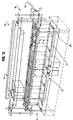
- a circuit-like conveying system 10 generally which includes a lower or treatment conveying line 12 generally, a lift or transfer mechanism 14 positioned at the end of the lower treatment line to retrieve work pieces therefrom.
- An upper or drying conveying line 16 is provided to receive treated work pieces from the lift or transfer mechanism 14.
- a second lift mechanism 18 is positioned at the end of the drying line 16 to retrieve dried work pieces therefrom and transfer those work pieces to a remote conveyor 20 (see Fig. 12).
- Untreated work pieces can be moved from the remote conveyor 20 to the entrance for the lower conveyor line 12.
- the work pieces are supported on a walking beam assembly 22 which is suspended from a hoist mechanism 24 which cooperates with a travel mechanism 26 that can be indexed forwardly one treatment station or backwardly one treatment station.
- the walking beam assembly 22, the hoist mechanism 24 and the travel mechanism 26 are interconnected, interrelated and work together to transport, raise and lower work pieces. However, in the description herein the assembly 22 and mechanisms 24 and 26 may be described or referred individually.
- the conveying system 10 includes a stationary support frame 28 which supports the lower conveying line 12, the upper conveying line 16, the hoist mechanism 24 and the travel mechanism 26. As seen in Figure 2, a work piece such as 30 is positioned above the treatment tank 32 for lowering into the tank 32 and subsequent treatment. It will also be appreciated that the circuit-like conveying system 10 has depth or is three dimensional and accommodates wide work pieces such as 30. It is also seen that the frame 28 spans a treatment tank such as 32.
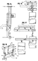
- the beam assembly 22 includes a pair of spaced rails 22A and 22B. Associated with each rail are L-shaped hanger engaging members such as 34. The beam assembly 22 is raised and lowered by a plurality of chains such as 36. A work piece hanger such as 38 is arranged to support a depending work piece 40 and to engage the hanger engaging member such as 34. As seen in Figure 3 work pieces such as 40, 42 and 44 can be suspended from the beam assembly 22 over tanks such as 46, 48 and 50.
- the beam assembly 22 is lowered and the work pieces 40, 42 and 44 are immersed in tanks 46, 48 and 50.
- the hangers such as 38 engage and rest on the side of the tanks and the hanger engaging members such as 34 are disengaged from the work pieces and can be moved to a position just below the hanger itself.
- the beam 22 is no longer engaged with the hangers and can be moved rearwardly one station as suggested in Figure 7.
- the beam 22 is raised and as it is raised it engages the hangers for work pieces 40, 42 and 44.
- the rearward hanger engaging member is open (see Fig. 7) and can pick up a new work piece such as 52 in Figure 10.
- the beam assembly 22 can be moved forwardly as in Figure 11 thereby indexing the work pieces one station forwardly. It will be noted that each station is spaced the same distance from an adjacent station.
- the hanger 38 supporting the work piece 40 and hanger engaging member bracket 34 are seen.
- the hanger 38 is lowered to rest on the edge of the tank such as 46 and the hanger engaging member 34 is shown in engagement with the hanger and the work piece 40 is shown there below.
- the hanger engaging member 34 is positioned below and disengaged from the hanger 38 and is in position to be moved rearwardly with respect to the tank.
- the hanger 38 is shown as a square tube and the hanger engaging member 34 includes an angle iron 34A which is positioned to engage the hanger 38 and support the same. It is seen that based upon the movement of the beam 22 downwardly, rearwardly, upwardly and forwardly the work pieces are moved in a rectangular pattern so as to move the work piece from one tank to another.
- Figure 12 shows the entire circuit-like conveying apparatus 10 in a diagrammatic fashion.
- the remote conveyor 20 and the lift mechanism 18 are shown whereby an untreated work piece can be removed from the conveyor 20, delivered to the lower conveyor line 12 onto the beam assembly 22 so as to be moved to the treatment tanks, then moved to the end of the conveyor 12 where the transfer mechanism 14 can retrieve the work piece and move it upwardly to the drying or upper conveyor 16.
- the upper conveyor 16 is a chain-like conveyor line that is positioned within an oven so as to form a drying line. Due to the heat to which the chain is exposed, the chain may lengthen and a take-up or tightening mechanism is provided within the oven so as to adjust the chain.
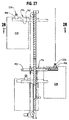
- a hook assembly 50 is provided that is secured to a stationary structure 51 secured to the frame 28 (See Figs. 1 and 13-17).
- the hook assembly includes an inverted U-shaped frame 52 that is secured to the stationary structure 51, two hingedly connected depending hooks 54 and 56 and an actuator bar 58 with an outwardly extending arm 59 that connects the hooks 54 and 56 for joint movement.
- a pneumatic cylinder 60 is connected at one end to the frame section 52 and at the other end to the actuator bar 58 via the arm 59. By retracting the piston the bar is rotated and the hooks 54 and 56 raised to a nonengaging position.
- the hooks By extending the piston rod the hooks are rotated to a position so that when the other work pieces are lowered the books engage a hangar such as 62 and prevent or restrain the associated work pieces from being lowered.
- the hooks can be rotated to an inoperative position and the previously restrained work piece engages the appropriate support on the beam, the work piece is moved to the next position and can be lowered and raised the other work pieces as seen in Fig. 17.
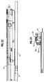
- the stationary frame 28 includes an end section such as 70 and a pair of rails 72A and 72B.
- the travel mechanism 26 and hoist mechanism 24 are associated with the frame 28.
- the beam assembly 22 which supports the various hangers from the hoist mechanism by a plurality of spaced chains such as 74 and 76 and the previously identified chain 36.
- the chains are spaced along the length of the beam so as to evenly raise and lower the beant
- the chains are vertically orientated but trained about a plurality of vertically orientated sprockets such as 78 and 80 which are secured to the travel frame 82 and rotate about a horizontal axis.
- the chains such as 74 and 76 are trained about the sprockets and are secured at their end to the pull rods 84 and 86.
- the pull rods 84 and 86 are operated by a winch or spool 88 about which cables such as 90 and 92 are trained.
- a cable such as 90 passes through a set of pullies which permit it to retract the pull rods such as 86.
- Those pullies include the horizontally arranged pulley 94, the pulley 96 and the pulley 98. It will be noted that the end of the cable 90 is grounded or secured to the frame 82 at a point 100 similarly the pullies 94 and 96 are secured to brackets that are also grounded.
- the hoist mechanism 24, the travel mechanism 26 and the beam assembly 22 is seen in elevational view and the beam assembly 22 is in the upper position.
- the entire beam assembly 22 and take up apparatus can be indexed one station forwardly or one station rearwardly so as to remove the work pieces from a first tank, raise them and move them to a second tank and then lower them.
- horizontal movement of the beam assembly 22 is controlled by the travel motor 110 drive shafts such as 112 stops 114 and 116 and the traveler or drive mechanism 118 generally(which is also seen in Figure 23). Fundamentally the traveler 118 moves back and forth between the stops 114 and 116 along the chain 120.
- the chain 120 is trained about an idler sprocket 122, a driven sprocket 124 and another idler sprocket 126.
- This the motor 110 rotates the drive shaft 112 which causes the sprocket 124 to rotate.
- the chain 120 is drawn beneath the idler sprocket 122 over the drive sprocket 124 and beneath the idler sprocket 126 to cause the traveler mechanism 118 to move toward one of the stops 114 or 116.
- the hoist mechanism 24 similarly moves and so does the walking beam assembly 22.
- the mechanism is then reversed and the walking beam is moved to the other end at stop 114. At that point the beam 22 may be raised so as to lift the appropriate hangers and this the work pieces have been indexed or moved one station forwardly.
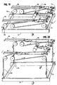
- the transfer or lift mechanism can be seen in Figures 24-28 inclusive. However reference is made to Figure 12 where the lift mechanisms 14 and 18 are shown at either end of the conveyor whereby work pieces can be lifted by a lift mechanism 14 from the end of the lower line 12 to the line 16. Other lift mechanism can move dried work pieces from the upper line 16 to the remote conveyor 20 and from the remote conveyor 20 untreated pieces can be removed and delivered to the lower conveyor 12.
- the lift includes a pair of side posts 152 and 154 which together with cross members 156 and 158 define a frame.
- a carrier 160 generally which can be moved vertically upwardly or downwardly in the larger frame.
- a pair of arm assemblies 162 and 164 are secured to the carrier and can move inwardly or outwardly and from one side to the other side of the carrier 160.
- the carrier 160 includes an upper cross member 166 and a lower cross member 168.
- a pair of vertical members 170 and 172 connect the cross members 166 and 168 and cooperate the posts 152 and 154 which have rails therein.
- the carrier 160 is raised or lowered by a driven chain and counter weight mechanism.
- the drive motor 174 is connected via a shaft such as 176 to chain drive sprockets 178 and 180 on the opposite sides of the lift.
- idler sprockets 182 and 184 are provided at the top of the lift mechanism.
- Drive chains 186 and 188 are trained about the drive sprockets such as 178 and 180.
- the chain such as 186 is connected to the carrier 160 by a bar such as 189.
- the chain 186 is also connected to the counter weight 190 but on the opposite side of the chain.
- the motor 174 can drive the chain so that the counter weight 190 moves upwardly and the carrier 160 via bar 189 descends.
- each of the arms 162 and 164 are secured to one of the rail-like members 170 and 172 at a position spaced from the top cross member 166 by brackets 171 and 173.
- Each of the arms includes a stationary section such as 192 and a telescoping section such as 194.
- the telescoping section rides on a I-beam like rail 196 as seen in Figure 26.
- a hanger supporting saddle such as 198 or 199 is mounted.
- the carrier motor 200 and carrier drive shafts 202 and 204 cause the carrier chains 210 and 212 to rotate to cause the telescoping sections of the arms to move inwardly or outwardly as seen in Figure 24.
- the carrier cross member 166 is spaced above the connection of the arm to the carrier so as to permit the saddle 198 to move thereunder.
- the entire carrier is sized so as to permit clearance of a work piece suspended from saddles such as 198 and 199.
- the carrier chain 212 is connected to the telescoping section 194 by a pinion 213 and rack 214 which cooperate to cause the arm to move laterally inwardly and outwardly.
- the saddle 198 is connected to one end of the telescoping section cable 216.
- the cable 216 is trained about the idler 218 and secured to the telescoping section at an end 220.
- the saddle 198 is also connected to a second telescoping section cable 222 which is trained about a idler 224 and connected to the telescoping section at end 226.
- a saddle such as 198 is shown supporting a hanger such as 226 and work piece such as 228.
- the telescoping section 194 of the arm as well as the hanger 226 and work piece 228 is moved from one side of the post 152 and carrier 160 to the other side (i.e. left to right or vise versa).
- the arm can be moved to a lower position or raised to an upper position and the saddle 198, hanger 226 and work piece 228 can move accordingly.
- an untreated work piece is delivered on a remote conveyor 20 so that a lift mechanism such as 18 can position a telescoping section such as 194 and hanger receiving saddles such as 198 and 199 under the hanger for the work piece and thus remove the work piece from the remote conveyor.
- the hanger rests on the saddles and the section is retracted under the action of the drive motor 200.
- the telescoping sections of the arms are moved to the other side of the lift and in position to be delivered to the treatment conveyor line such as 12.
- There the hanger and work piece are deposited on the hanger engaging bracket such as 34 associated with the beam 22 and the untreated pieces are added to the conveyor and moved as shown in Figs. 3, 5, 7, 10 and 11.
- the hoist and travel mechanism 24 and 26 cause the untreated piece to move into and out of the various treatment tanks and to the exit end of the lower line.
- a lift mechanism 14 is provided and arms on the lift mechanism are extended and engage the hanger on the appropriate saddles.
- the arm is then retracted and lifted to the second line such as 16.
- There the arms extend and the hanger is deposited on the line 16.
- the treated piece is moved along the second or drying line to its exit end.
- There the lift mechanism 18 extends the arms and engages the hanger using the saddles.
- the arms are retracted, moved to a lower position, and caused to move to the other side of the lift mechanism and the hanger and work piece are deposited on the remote conveyor 20.
- the cycle is then repeated. It will be appreciated the appropriate controls are provided for the operation of the system.
Landscapes
- Intermediate Stations On Conveyors (AREA)
- Specific Conveyance Elements (AREA)
- Automatic Assembly (AREA)
Applications Claiming Priority (2)
| Application Number | Priority Date | Filing Date | Title |
|---|---|---|---|
| US307546 | 1981-10-01 | ||
| US09/307,546 US6253907B1 (en) | 1999-05-07 | 1999-05-07 | Conveying system for work pieces |
Publications (2)
| Publication Number | Publication Date |
|---|---|
| EP1050495A2 true EP1050495A2 (fr) | 2000-11-08 |
| EP1050495A3 EP1050495A3 (fr) | 2004-03-31 |
Family
ID=23190218
Family Applications (1)
| Application Number | Title | Priority Date | Filing Date |
|---|---|---|---|
| EP00301939A Withdrawn EP1050495A3 (fr) | 1999-05-07 | 2000-03-09 | Système de transport de pièces |
Country Status (3)
| Country | Link |
|---|---|
| US (2) | US6253907B1 (fr) |
| EP (1) | EP1050495A3 (fr) |
| CA (1) | CA2302069C (fr) |
Cited By (4)
| Publication number | Priority date | Publication date | Assignee | Title |
|---|---|---|---|---|
| US6699329B2 (en) | 2001-05-25 | 2004-03-02 | George Koch Sons, Llc | Coating and curing system |
| EP1849890A1 (fr) * | 2006-04-28 | 2007-10-31 | Wolf-Dieter Franz | Installation galvanique avec dispositif convoyeur pour le mouvement du cadre |
| WO2009095152A1 (fr) * | 2008-01-29 | 2009-08-06 | Volkswagen Aktiengesellschaft | Installation de traitement de surface d'objets, notamment de carrosseries de véhicules |
| CN106516633A (zh) * | 2016-12-09 | 2017-03-22 | 广东天机工业智能系统有限公司 | 循环生产线 |
Families Citing this family (31)
| Publication number | Priority date | Publication date | Assignee | Title |
|---|---|---|---|---|
| US6575177B1 (en) * | 1999-04-27 | 2003-06-10 | Applied Materials Inc. | Semiconductor substrate cleaning system |
| DE10039062B4 (de) * | 2000-08-10 | 2007-02-01 | Schuler Pressen Gmbh & Co. Kg | Transferpresse sowie eine Vorrichtung zum Be-bzw. Entladen von Werkstücken |
| US6634484B2 (en) * | 2001-04-26 | 2003-10-21 | Honda Of Canada Mfg., A Division Of Honda Canada Inc. | Transfer and tilt apparatus |
| US20050279973A1 (en) * | 2004-03-09 | 2005-12-22 | Rea Jared A | Luggage cart vertical reciprocating conveyor |
| DE102004025525B3 (de) * | 2004-05-25 | 2005-12-08 | Eisenmann Maschinenbau Gmbh & Co. Kg | Verfahren und Vorrichtung zum Trocknen von Gegenständen, insbesondere von lackierten Fahrzeugkarosserien |
| US6983837B1 (en) * | 2004-07-30 | 2006-01-10 | Chun-Liang Chen | Finished product receiving unit used in a corrugated metal sheet member making machine |
| US7097023B1 (en) * | 2004-07-30 | 2006-08-29 | Chun-Liang Chen | Finished product receiving unit of a corrugated metal sheet member making machine |
| US20060068094A1 (en) * | 2004-09-29 | 2006-03-30 | Cole David J | Production paint shop design |
| US7534297B2 (en) * | 2005-04-19 | 2009-05-19 | The Boeing Company | Single item workflow manufacturing system and method |
| KR100969122B1 (ko) * | 2007-12-14 | 2010-07-09 | 현대자동차주식회사 | 트래버서를 이용한 타이어 자동 공급 장치 |
| US20090248190A1 (en) * | 2008-03-28 | 2009-10-01 | Spangler John M | Portable modular manufacturing system |
| US20100008749A1 (en) * | 2008-07-08 | 2010-01-14 | Caterpillar Inc. | Modular paint line including an immersion station |
| US10980925B1 (en) | 2008-10-14 | 2021-04-20 | A Hoyos Llc | High definition liposculpture |
| KR101063495B1 (ko) * | 2009-06-15 | 2011-09-07 | 현대자동차주식회사 | 트래버스 장치 |
| US20140046471A1 (en) * | 2012-08-10 | 2014-02-13 | Globe Machine Manufacturing Company | Robotic scanning and processing systems and method |
| US9123196B1 (en) * | 2012-09-10 | 2015-09-01 | Haytham Salem | Rotating sandwich dispenser assembly |
| US9347603B2 (en) | 2013-06-20 | 2016-05-24 | Taggart Global, Llc | Counterweight hoisting apparatus |
| US10112221B1 (en) * | 2014-07-08 | 2018-10-30 | Michael P. Pedziwiatr | Ultrasonic processing apparatus and method |
| CN104528038B (zh) * | 2014-12-26 | 2017-03-08 | 昆山精讯电子技术有限公司 | 液晶模组分类包装装置 |
| CN104528037B (zh) * | 2014-12-26 | 2016-09-14 | 昆山精讯电子技术有限公司 | 液晶模组分类包装用托盘传送装置 |
| CN109178817A (zh) * | 2017-06-29 | 2019-01-11 | 无锡邦得机械有限公司 | 清洗、烘干线及其零件运输装置 |
| USD883767S1 (en) | 2018-10-10 | 2020-05-12 | A Hoyos Llc | Handle |
| DE102019119053A1 (de) * | 2019-07-15 | 2021-01-21 | Eisenmann Se | Behandlungsanlage zum Behandeln von Gegenständen und Verfahren zum Behandeln von Gegenständen mit einer solchen Behandlungsanlage |
| CN110745534A (zh) * | 2019-10-21 | 2020-02-04 | 上海君屹工业自动化股份有限公司 | 动力电池模组机器人协同上料站 |
| US20210407824A1 (en) | 2020-06-30 | 2021-12-30 | Applied Materials, Inc. | Spm processing of substrates |
| CN112591211B (zh) * | 2020-11-25 | 2022-06-03 | 上海鹰卫精密机械有限公司 | 一种砖塔式分选机用自动上下料设备 |
| CN112496837B (zh) * | 2020-12-10 | 2025-01-14 | 厦门宏泰智能制造有限公司 | 一种服务器自动下料机 |
| CN114178230B (zh) * | 2021-11-17 | 2023-06-16 | 贵州德科纳精密设备制造有限公司 | 气门自动清洗机 |
| CN117864763B (zh) * | 2024-03-11 | 2024-05-17 | 常州市昌隆电机股份有限公司 | 一种电机转轴抓取输送机构 |
| CN118047229B (zh) * | 2024-03-15 | 2024-08-30 | 泰山石膏(菏泽)有限公司 | 用于石膏板生产的自动摞包装置 |
| CN118635236A (zh) * | 2024-07-30 | 2024-09-13 | 郯城县亿顺钢化玻璃有限责任公司 | 一种玻璃清洗机 |
Family Cites Families (20)
| Publication number | Priority date | Publication date | Assignee | Title |
|---|---|---|---|---|
| US3123197A (en) | 1964-03-03 | Transfer mechanism | ||
| US2789569A (en) | 1955-08-24 | 1957-04-23 | Udylite Corp | Plating machine |
| US2866565A (en) | 1957-04-02 | 1958-12-30 | Capitol Prod Corp | Proofer control system |
| US3024794A (en) * | 1959-05-19 | 1962-03-13 | Udylite Corp | Auxiliary work transfer mechanism for plating machines |
| CA675720A (en) * | 1959-08-13 | 1963-12-10 | Standard Telephones And Cables Mfg. Co. (Canada) Ltd. | Conveying system |
| US3082495A (en) * | 1960-01-15 | 1963-03-26 | Miller Engineering Corp | Conveyor transfer machine |
| US3381695A (en) * | 1966-08-03 | 1968-05-07 | Udylite Corp | Conveying apparatus |
| US3601134A (en) * | 1968-04-29 | 1971-08-24 | Clinton Supply Co | Automatic and manual plating machine |
| US3658197A (en) * | 1970-06-01 | 1972-04-25 | Lockheed Aircraft Corp | Programmable apparatus for conveying articles through successive process steps |
| US4597707A (en) * | 1984-08-17 | 1986-07-01 | General Machine Design, Inc. | Automatic operating palletizer |
| US4749465A (en) | 1985-05-09 | 1988-06-07 | Seagate Technology | In-line disk sputtering system |
| JPH0657879B2 (ja) | 1987-10-31 | 1994-08-03 | 日大工業株式会社 | バスケット式電着塗装装置 |
| CA1319162C (fr) * | 1988-09-12 | 1993-06-15 | Fmc Corporation | Palettiseur robotise |
| US5012918A (en) | 1988-12-30 | 1991-05-07 | Therma-Tron-X, Inc. | Intermittent work conveying apparatus |
| US4942956A (en) | 1988-12-30 | 1990-07-24 | Therma-Tron-X, Inc. | Part indexing and positioning apparatus |
| US5452981A (en) * | 1991-03-06 | 1995-09-26 | Leland D. Blatt | Automatic tool changer |
| DE4129829A1 (de) * | 1991-09-07 | 1993-03-11 | Brodhag Angelika | Selbsttaetige entladevorrichtung fuer riegelfoermige nahrungsmittel |
| US5483876A (en) * | 1993-12-21 | 1996-01-16 | Trantek, Incorporated | Workpart transfer mechanism for stamping press |
| US5439015A (en) * | 1994-03-28 | 1995-08-08 | Shibano; Yoshihide | Cleaning apparatus |
| US5449268A (en) * | 1994-04-04 | 1995-09-12 | Western Atlas, Inc. | Variable speed drive mechanism with dwell |
-
1999
- 1999-05-07 US US09/307,546 patent/US6253907B1/en not_active Expired - Fee Related
-
2000
- 2000-03-09 EP EP00301939A patent/EP1050495A3/fr not_active Withdrawn
- 2000-03-23 CA CA002302069A patent/CA2302069C/fr not_active Expired - Fee Related
-
2001
- 2001-02-15 US US09/784,754 patent/US6345635B2/en not_active Expired - Fee Related
Cited By (6)
| Publication number | Priority date | Publication date | Assignee | Title |
|---|---|---|---|---|
| US6699329B2 (en) | 2001-05-25 | 2004-03-02 | George Koch Sons, Llc | Coating and curing system |
| EP1849890A1 (fr) * | 2006-04-28 | 2007-10-31 | Wolf-Dieter Franz | Installation galvanique avec dispositif convoyeur pour le mouvement du cadre |
| WO2009095152A1 (fr) * | 2008-01-29 | 2009-08-06 | Volkswagen Aktiengesellschaft | Installation de traitement de surface d'objets, notamment de carrosseries de véhicules |
| US8469042B2 (en) | 2008-01-29 | 2013-06-25 | Volkswagen Aktiengesellschaft | Treatment system and method for the surface treatment of workpieces, particularly vehicle bodies |
| CN106516633A (zh) * | 2016-12-09 | 2017-03-22 | 广东天机工业智能系统有限公司 | 循环生产线 |
| CN106516633B (zh) * | 2016-12-09 | 2019-06-21 | 广东天机工业智能系统有限公司 | 循环生产线 |
Also Published As
| Publication number | Publication date |
|---|---|
| EP1050495A3 (fr) | 2004-03-31 |
| CA2302069C (fr) | 2005-02-01 |
| US6253907B1 (en) | 2001-07-03 |
| US6345635B2 (en) | 2002-02-12 |
| CA2302069A1 (fr) | 2000-11-07 |
| US20010010281A1 (en) | 2001-08-02 |
Similar Documents
| Publication | Publication Date | Title |
|---|---|---|
| US6253907B1 (en) | Conveying system for work pieces | |
| US4256222A (en) | Transfer conveyor for the transfer of piece goods from a first roller track conveyor to a second roller track conveyor | |
| US5108345A (en) | Apparatus and method for loading live fowl onto a conveyor | |
| US4252486A (en) | System for transferring and storing elongated elements | |
| CN207748446U (zh) | 一种铝型材卧式喷涂预处理及上架装置 | |
| US2944655A (en) | Apparatus for unloading articles from a moving conveyor | |
| US3219206A (en) | Automatic textile beam transfer apparatus | |
| CN109987390A (zh) | 一种铝型材卧式喷涂预处理及上架装置 | |
| US3851778A (en) | Transport system for goods carriers | |
| CN211392597U (zh) | 铁心柱原料钢卷自动存取单卷或多卷卧式钢卷的堆垛机 | |
| CN117163528B (zh) | 一种钢管布卷搬运缓存系统 | |
| CN212831047U (zh) | 一种吊挂流水线的上下料装置 | |
| CN210418272U (zh) | 一种垂直输送装置及输送系统 | |
| US4756401A (en) | Load transfer apparatus for power-driven overhead conveyor | |
| JPH1135112A (ja) | 棚入れ装置、搬送物を棚に収容する棚入れ方法及び棚入れ装置において受取コンベアを受け取り高さに設定する方法 | |
| US6048157A (en) | Turkey coop unloading apparatus and method | |
| US2893573A (en) | Piler mechanism for metal sheets | |
| JPH02150233A (ja) | 屠殺屍体の皮の剥ぎ取り方法及びその装置 | |
| US4183514A (en) | System for spreading flexible material | |
| CN110980380A (zh) | 一种用于片状产品生产的连续落料装置 | |
| JPS6019602A (ja) | 取扱物の移載装置 | |
| US3599417A (en) | Method of placing packages of strand on a twist frame | |
| JP2000064799A (ja) | 隧道構築用覆工材の搬送システム | |
| US3934736A (en) | Spring stacker | |
| US3982745A (en) | Fabric supplying and cutting system |
Legal Events
| Date | Code | Title | Description |
|---|---|---|---|
| PUAI | Public reference made under article 153(3) epc to a published international application that has entered the european phase |
Free format text: ORIGINAL CODE: 0009012 |
|
| 17P | Request for examination filed |
Effective date: 20000325 |
|
| AK | Designated contracting states |
Kind code of ref document: A2 Designated state(s): AT BE CH CY DE DK ES FI FR GB GR IE IT LI LU MC NL PT SE |
|
| AX | Request for extension of the european patent |
Free format text: AL;LT;LV;MK;RO;SI |
|
| RIC1 | Information provided on ipc code assigned before grant |
Ipc: 7B 65G 49/04 A |
|
| PUAL | Search report despatched |
Free format text: ORIGINAL CODE: 0009013 |
|
| RIC1 | Information provided on ipc code assigned before grant |
Ipc: 7B 65G 61/00 B Ipc: 7B 65G 49/04 A |
|
| AK | Designated contracting states |
Kind code of ref document: A3 Designated state(s): AT BE CH CY DE DK ES FI FR GB GR IE IT LI LU MC NL PT SE |
|
| AX | Request for extension of the european patent |
Extension state: AL LT LV MK RO SI |
|
| AKX | Designation fees paid |
Designated state(s): AT BE CH CY DE DK ES FI FR GB GR IE IT LI LU MC NL PT SE |
|
| STAA | Information on the status of an ep patent application or granted ep patent |
Free format text: STATUS: THE APPLICATION IS DEEMED TO BE WITHDRAWN |
|
| 18D | Application deemed to be withdrawn |
Effective date: 20041001 |