EP1050868A2 - Dispositif de scellement - Google Patents
Dispositif de scellement Download PDFInfo
- Publication number
- EP1050868A2 EP1050868A2 EP00302865A EP00302865A EP1050868A2 EP 1050868 A2 EP1050868 A2 EP 1050868A2 EP 00302865 A EP00302865 A EP 00302865A EP 00302865 A EP00302865 A EP 00302865A EP 1050868 A2 EP1050868 A2 EP 1050868A2
- Authority
- EP
- European Patent Office
- Prior art keywords
- section
- sealer
- inserting head
- sections
- sealers
- Prior art date
- Legal status (The legal status is an assumption and is not a legal conclusion. Google has not performed a legal analysis and makes no representation as to the accuracy of the status listed.)
- Withdrawn
Links
- 230000037431 insertion Effects 0.000 description 6
- 238000003780 insertion Methods 0.000 description 6
- 238000007789 sealing Methods 0.000 description 2
- 229920003002 synthetic resin Polymers 0.000 description 2
- 239000000057 synthetic resin Substances 0.000 description 2
- 239000004677 Nylon Substances 0.000 description 1
- 239000004743 Polypropylene Substances 0.000 description 1
- 230000000694 effects Effects 0.000 description 1
- 239000000463 material Substances 0.000 description 1
- 229920001778 nylon Polymers 0.000 description 1
- 229920000728 polyester Polymers 0.000 description 1
- -1 polypropylene Polymers 0.000 description 1
- 229920001155 polypropylene Polymers 0.000 description 1
Images


Classifications
-
- G—PHYSICS
- G09—EDUCATION; CRYPTOGRAPHY; DISPLAY; ADVERTISING; SEALS
- G09F—DISPLAYING; ADVERTISING; SIGNS; LABELS OR NAME-PLATES; SEALS
- G09F3/00—Labels, tag tickets, or similar identification or indication means; Seals; Postage or like stamps
- G09F3/02—Forms or constructions
- G09F3/03—Forms or constructions of security seals
- G09F3/0305—Forms or constructions of security seals characterised by the type of seal used
- G09F3/037—Forms or constructions of security seals characterised by the type of seal used having tie-wrap sealing means
-
- G—PHYSICS
- G09—EDUCATION; CRYPTOGRAPHY; DISPLAY; ADVERTISING; SEALS
- G09F—DISPLAYING; ADVERTISING; SIGNS; LABELS OR NAME-PLATES; SEALS
- G09F3/00—Labels, tag tickets, or similar identification or indication means; Seals; Postage or like stamps
- G09F3/08—Fastening or securing by means not forming part of the material of the label itself
- G09F3/14—Fastening or securing by means not forming part of the material of the label itself by strings, straps, chains, or wires
-
- Y—GENERAL TAGGING OF NEW TECHNOLOGICAL DEVELOPMENTS; GENERAL TAGGING OF CROSS-SECTIONAL TECHNOLOGIES SPANNING OVER SEVERAL SECTIONS OF THE IPC; TECHNICAL SUBJECTS COVERED BY FORMER USPC CROSS-REFERENCE ART COLLECTIONS [XRACs] AND DIGESTS
- Y10—TECHNICAL SUBJECTS COVERED BY FORMER USPC
- Y10T—TECHNICAL SUBJECTS COVERED BY FORMER US CLASSIFICATION
- Y10T24/00—Buckles, buttons, clasps, etc.
- Y10T24/14—Bale and package ties, hose clamps
-
- Y—GENERAL TAGGING OF NEW TECHNOLOGICAL DEVELOPMENTS; GENERAL TAGGING OF CROSS-SECTIONAL TECHNOLOGIES SPANNING OVER SEVERAL SECTIONS OF THE IPC; TECHNICAL SUBJECTS COVERED BY FORMER USPC CROSS-REFERENCE ART COLLECTIONS [XRACs] AND DIGESTS
- Y10—TECHNICAL SUBJECTS COVERED BY FORMER USPC
- Y10T—TECHNICAL SUBJECTS COVERED BY FORMER US CLASSIFICATION
- Y10T24/00—Buckles, buttons, clasps, etc.
- Y10T24/14—Bale and package ties, hose clamps
- Y10T24/1402—Packet holders
- Y10T24/141—Plastic bands
-
- Y—GENERAL TAGGING OF NEW TECHNOLOGICAL DEVELOPMENTS; GENERAL TAGGING OF CROSS-SECTIONAL TECHNOLOGIES SPANNING OVER SEVERAL SECTIONS OF THE IPC; TECHNICAL SUBJECTS COVERED BY FORMER USPC CROSS-REFERENCE ART COLLECTIONS [XRACs] AND DIGESTS
- Y10—TECHNICAL SUBJECTS COVERED BY FORMER USPC
- Y10T—TECHNICAL SUBJECTS COVERED BY FORMER US CLASSIFICATION
- Y10T24/00—Buckles, buttons, clasps, etc.
- Y10T24/14—Bale and package ties, hose clamps
- Y10T24/1498—Plastic band
Definitions
- the present invention relates to a sealer for attaching and sealing tags such as bland labels, price tags, material description, instruction manual, etc. to cloths, shoes, bags, and other products, and more particularly to a sealer that can smoothly attach tags when it is set to a special-purpose tag attaching tool for attaching tags as specified above.
- tags such as bland labels, price tags, material description, instruction manual, etc.
- a sealer as shown in FIG. 10 has been used for banding together clothes, women's boots, sandals, shoes, etc. or for attaching bland labels, price tags, etc.
- the sealer comprises a filament section 5 for forming a loop by passing a tag, an inserting head section 6 equipped on one end thereof, and a socket section 8 equipped with an insertion hole 7 equipped at the other end of the filament section 5 and for allowing the relevant inserting head section 6 to pass. And a plurality of sealers 4 are temporarily fixed to two bars 11 in parallel to one another in such a manner to enable easy removal.
- FIG. 10 is integrally molded preferably with synthetic resin, etc., and in particular, the filament section 5 is elongated to exhibit extremely strong resistance against pulling.
- a latching piece 9 which is a hook mounted near the insertion hole 7, opens, and this causes the neck part 6a of the inserting head section 6 is inversibly fixed in the socket section 8, and a loop-form label attaching condition is completed, and sealing is achieved.
- these sealers are loaded in a special-purpose tag attaching tool (gun), and it is used by operating a lever 18a so as to set the inserting head into the socked section not only for banding together boots, sandals, and shoes but also primarily for fixing bland labels and tags T that carry the instruction manual of a product.
- gun special-purpose tag attaching tool
- the conventional sealer described above has a problem in that some of the inserting head sections of sealers inherently arranged in parallel to one another turn to different directions as shown in FIG. 10, respectively, depending on the storage condition, and are not loaded to the driving pins of the gun in a correct direction and jamming condition occurs when the sealer is set to the special-purpose device (gun) that can continuously seal by pulling the lever.
- the inserting head sections are not properly fitted to the socket section, causing failure of the device.
- the present invention basically adopts a configuration described as follows. That is, the present invention relates to a sealer comprising a filament section with flexibility, an inserting head section with a proper engaging section located at one end of the filament section, and a socket section located at the other end of the filament section and equipped with a hole for irreversibly passing the inserting head section, wherein a plurality of said sealers having the filament sections arranged adjacent to and in parallel to one another, and at the same time, a plurality of the inserting head sections or their neighboring sections and a plurality of said socket sections or their neighboring sections arranged adjacent to one another connected, respectively, to connecting bar sections individually provided, and the vicinity of the inserting head sections further connected to one another with the latching pieces.
- sealer according to the present invention first respective portions of the sealers located in the vicinity of the inserting head sections are connected to each other with separate latching pieces, even when improper external force is applied to the sealers during transportation or storage, the directions of the inserting head section are not misaligned, and the operability when the sealer is set to the tag attaching tool can be improved.
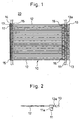
- FIG. 1 is a front view showing the configuration of one specific example of the sealer related to the present invention
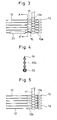
- FIG. 2 is an enlarged plan view showing the essential part of the sealer.
- the sealer 20 comprises a filament section 12 with flexibility, an inserting head section 13 with a proper engaging section 13a located at one end of the filament section 12, and a socket section 15 located at the other end of the filament section 12 and equipped with a hole 14 for irreversibly passing the inserting head section 13, a plurality of said sealers 10 having the filament sections 12 arranged adjacent to and in parallel to one another, and at the same time, a plurality of the inserting head sections 13 or their neighboring sections and a plurality of said socket sections 15 or their neighboring sections arranged adjacent to one another being connected, respectively, to connecting bar sections 11 individually provided, and a portion located in the vicinity of the inserting head sections of each of the filament portion further connected to one another with the latching pieces 16.
- the sealer 20 according to the present invention is integrally molded generally with synthetic resin such as nylon, polypropylene, polyester, etc. as in the case of conventional sealers.
- the basic configuration of the sealer 20 related to the present invention is nearly same as that of the conventional sealer, and further at the socket section 15, an insertion hole 14 for irreversibly passing the inserting head section 13 is equipped.
- the cross-sectional profile of the filament section 12 may be any of circle, flattened shape, or rectangle.
- an engaging section 17 to which the engaging section 13a formed to have a diameter reduced stepwise on part of the inserting head section 13 is able to be latched is provided.
- the engaging section 17 is deformably formed protrudably in the insertion hole 14.
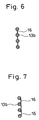
- the sealer 10 in the present embodiment has latching pieces 16 for connecting the base end parts 13b of adjacent inserting head sections 13 each other as shown in FIG. 3 and 4 are disposed on the filament section 12 side. Consequently, since the inserting head section 13 is connected at 2 places vertically to the latching piece 16 and the bar 11, the direction of the head end is not deviated.
- the portion of the latching piece 16 connected to part of other inserting head section 13 is formed slenderly for easy cutting.
- the sealers 10 are temporarily fixed to the bar 11, respectively, in parallel. Consequently, only pulling the lever 18a after loading the sealers to the tag attaching tool can easily separate the sealers one by one and can attach labels, etc. to the sealers.
- the latching piece 16 that connect adjacent inserting head sections 13 may be formed in the form of a thin string.
- the latching piece 16 is only required to hold the direction of the inserting head section 13, and does not need the strength exceeding that requirement.
- FIG. 7 is an enlarged cross-sectional view showing an essential part of still another embodiment of the sealer.
- the latching piece 16 is formed in such a manner to connect the cross-sectional-side edge of the inserting head section 13. Even when it is formed in this way, the direction of the inserting head section 13 is able to hold constantly.
- FIG. 8 is a perspective view showing the condition in which the sealer according to the present invention is set to the special-purpose tag attaching tool (gun) and FIG. 9 is a plan view showing an essential part of the tag attaching tool for using the sealer according to the present invention.
- the tag attaching tool 18
- longitudinal grooves 21, 22 are formed on the right and the left for inserting the connecting bars 11 of the sealer 20.
- the connecting bar 11 for connecting the socket section 15 of the sealer 20 is inserted, and to the longitudinal groove 22, the connecting bar 11 for connecting the inserting head section 13 is inserted.
- tag attaching pins 23 driven by operating the lever 18a illustrated are disposed on the side of the longitudinal groove 22, and separates the inserting head section 13 from the connecting section 11a of the connecting bar 11 and pushes out the sealer one by one forwards along the cylindrical guide needle 24.
- the socket section 15 with the bar 11 for connecting this to the longitudinal groove 21 inserted is separated from the connecting section of the connecting bar 11 by the press-out belt 25, and pushed out one by one forward along the curved socket section guide 26.
- the socket section 15 pushed out along the socket section guide 26 turns the direction 90° and fits to the inserting head section 13 pushed out by the tag attaching pin 23 at the head end portion in the insertion hole 14.
- the socket section guide 26 changes the direction about 90° with the inside deformed cylindrically so that the press-out belt 25 is able to advance while being bent. And it is configured in such a manner that the timing of the head end of the press-out belt 25 reaches the top end of the socket section guide 26 coincides with the timing of the tag-attaching pin 23 reaching the top end of the socket section guide 26. In this way, the sealer 20 is able to attach labels successively and continuously to products, etc.
- the latching piece 16 connecting sealers 10 one another is formed in the form of a cone and the thin part of the head end is connected to the neighboring inserting head section 13.
- the latching piece 16 may be a pyramid in place of a cone. Even when the latching piece is formed in the form of a pyramid, the thin part of the head end is connected to the neighboring inserting head section 13. Even when configured in this way, the direction is not deviated because the inserting head section 13 is connected with the bar 11 at two places of the latching piece 16.
- the latching piece 16 connecting single sealers 10 one another may be disposed at the head end side of the inserting head section 13. Even when configured in this way, the direction is not deviated because the inserting head section 13 is connected with the bar 11 at two places of the latching piece 16.
- the latching piece 16 connecting single sealers 10 one another is disposed every other sealer alternately on the head end side of the inserting head section 13 and on the filament section 12 side. Even when the latching piece is formed in the form of a pyramid, the direction is not deviated because the inserting head section 13 is connected with the bar 11 at two places of the latching piece 16.
- the filament section used in the sealer related to the present invention may have the cross section in any form of circle, flattened shape, ellipse, or rectangle.
- the size of the socket section is preferably visually small enough for enabling easy handling.
- the directions of inserting head sections do not deviate, respectively, when the sealer is set to the tag attaching tool, or during storage or in transit, and the sealer is able to be smoothly pushed out by the tag attaching pin and generation of jam is able to be prevented.
- sealer when used as a single sealer, it is able to be readily operated when labels, etc. are attached to products.
Landscapes
- Engineering & Computer Science (AREA)
- Physics & Mathematics (AREA)
- General Physics & Mathematics (AREA)
- Theoretical Computer Science (AREA)
- Computer Security & Cryptography (AREA)
- Labeling Devices (AREA)
- Basic Packing Technique (AREA)
Applications Claiming Priority (2)
| Application Number | Priority Date | Filing Date | Title |
|---|---|---|---|
| JP11097859A JP2000289727A (ja) | 1999-04-05 | 1999-04-05 | 封緘具 |
| JP9785999 | 1999-04-05 |
Publications (1)
| Publication Number | Publication Date |
|---|---|
| EP1050868A2 true EP1050868A2 (fr) | 2000-11-08 |
Family
ID=14203488
Family Applications (1)
| Application Number | Title | Priority Date | Filing Date |
|---|---|---|---|
| EP00302865A Withdrawn EP1050868A2 (fr) | 1999-04-05 | 2000-04-05 | Dispositif de scellement |
Country Status (3)
| Country | Link |
|---|---|
| US (1) | US6352156B1 (fr) |
| EP (1) | EP1050868A2 (fr) |
| JP (1) | JP2000289727A (fr) |
Families Citing this family (5)
| Publication number | Priority date | Publication date | Assignee | Title |
|---|---|---|---|---|
| US6735895B2 (en) * | 2000-08-11 | 2004-05-18 | Toska Co., Ltd. | Fixture of indication tag or the like having a magnetic body for marker |
| USD514425S1 (en) | 2004-05-27 | 2006-02-07 | Brammall, Inc. | Locking device |
| US20060266087A1 (en) * | 2004-11-12 | 2006-11-30 | Hamilton Eric K | Locking device |
| JP2010280410A (ja) * | 2009-06-04 | 2010-12-16 | M I T Internatl:Kk | ループピン |
| JP7639216B1 (ja) | 2024-05-22 | 2025-03-04 | 株式会社コーテックス | 係止片取付装置及びループピン |
Family Cites Families (4)
| Publication number | Priority date | Publication date | Assignee | Title |
|---|---|---|---|---|
| US5501002A (en) * | 1994-06-20 | 1996-03-26 | Fukami; Syouichi | Tag fastening device |
| JP3390983B2 (ja) * | 1995-05-17 | 2003-03-31 | ジェイ・イー株式会社 | タッグ吊持用ループピン装着具 |
| JPH10116034A (ja) * | 1996-10-14 | 1998-05-06 | J Ii Kk | タグ吊持用のフレキシブルピン材 |
| US6101683A (en) * | 1998-04-02 | 2000-08-15 | Avery Dennison Corporation | Loop fastener, fastener clip including same and loop fastener dispensing tool |
-
1999
- 1999-04-05 JP JP11097859A patent/JP2000289727A/ja active Pending
-
2000
- 2000-04-05 US US09/542,336 patent/US6352156B1/en not_active Expired - Fee Related
- 2000-04-05 EP EP00302865A patent/EP1050868A2/fr not_active Withdrawn
Also Published As
| Publication number | Publication date |
|---|---|
| JP2000289727A (ja) | 2000-10-17 |
| US6352156B1 (en) | 2002-03-05 |
Similar Documents
| Publication | Publication Date | Title |
|---|---|---|
| US5692274A (en) | Plastic fastener for shoe-lasting applications | |
| US6371293B2 (en) | Fastener assembly | |
| US5339954A (en) | Clip of attachments | |
| US6527030B2 (en) | Sealing implement | |
| US9193492B2 (en) | Method of applying notched fastener stock | |
| EP1112561B1 (fr) | Attache en plastique pour vetement et procede d'utilisation correspondant | |
| EP1050868A2 (fr) | Dispositif de scellement | |
| EP1120767A1 (fr) | Boucle d'attachement | |
| EP1088762B1 (fr) | Attache de scellage | |
| US6595360B2 (en) | Fastening element | |
| EP1329867B1 (fr) | Elément de fixation | |
| EP1489013B1 (fr) | Pistolet de fixation d'épingles en boucle | |
| CA2326843A1 (fr) | Fermeture a boucle, clip de fermeture comprenant ladite fermeture a boucle, et distributeur de fermetures a boucle | |
| AU677336B2 (en) | Seal | |
| US6009997A (en) | Loop fastener, fastener clip including same and loop fastener dispensing tool | |
| EP1083537A2 (fr) | Instrument de scellage | |
| JP4147285B2 (ja) | 折り返し型封緘具 | |
| WO1994009665A1 (fr) | Attache et systeme d'attache destines a des applications de montage de chaussures | |
| MXPA99008576A (en) | Attacher of loop pin for hooking tag | |
| DE2608208A1 (de) | Einrichtung zur kennzeichnung von warenpackungen, insbesondere von gefrierpackungen | |
| DE7602127U1 (de) | Einrichtung zur Kennzeichnung von Warenpackungen insbesondere von Gefrierpackungen |
Legal Events
| Date | Code | Title | Description |
|---|---|---|---|
| PUAI | Public reference made under article 153(3) epc to a published international application that has entered the european phase |
Free format text: ORIGINAL CODE: 0009012 |
|
| AK | Designated contracting states |
Kind code of ref document: A2 Designated state(s): AT BE CH CY DE DK ES FI FR GB GR IE IT LI LU MC NL PT SE |
|
| AX | Request for extension of the european patent |
Free format text: AL;LT;LV;MK;RO;SI |
|
| STAA | Information on the status of an ep patent application or granted ep patent |
Free format text: STATUS: THE APPLICATION IS DEEMED TO BE WITHDRAWN |
|
| 18D | Application deemed to be withdrawn |
Effective date: 20020501 |