EP1329867B1 - Elément de fixation - Google Patents
Elément de fixation Download PDFInfo
- Publication number
- EP1329867B1 EP1329867B1 EP03250317A EP03250317A EP1329867B1 EP 1329867 B1 EP1329867 B1 EP 1329867B1 EP 03250317 A EP03250317 A EP 03250317A EP 03250317 A EP03250317 A EP 03250317A EP 1329867 B1 EP1329867 B1 EP 1329867B1
- Authority
- EP
- European Patent Office
- Prior art keywords
- fastening element
- sections
- filament
- section
- connection bars
- Prior art date
- Legal status (The legal status is an assumption and is not a legal conclusion. Google has not performed a legal analysis and makes no representation as to the accuracy of the status listed.)
- Expired - Lifetime
Links
Images





Classifications
-
- B—PERFORMING OPERATIONS; TRANSPORTING
- B65—CONVEYING; PACKING; STORING; HANDLING THIN OR FILAMENTARY MATERIAL
- B65C—LABELLING OR TAGGING MACHINES, APPARATUS, OR PROCESSES
- B65C7/00—Affixing tags
-
- G—PHYSICS
- G09—EDUCATION; CRYPTOGRAPHY; DISPLAY; ADVERTISING; SEALS
- G09F—DISPLAYING; ADVERTISING; SIGNS; LABELS OR NAME-PLATES; SEALS
- G09F3/00—Labels, tag tickets, or similar identification or indication means; Seals; Postage or like stamps
- G09F3/02—Forms or constructions
- G09F3/03—Forms or constructions of security seals
- G09F3/0305—Forms or constructions of security seals characterised by the type of seal used
- G09F3/037—Forms or constructions of security seals characterised by the type of seal used having tie-wrap sealing means
-
- B—PERFORMING OPERATIONS; TRANSPORTING
- B65—CONVEYING; PACKING; STORING; HANDLING THIN OR FILAMENTARY MATERIAL
- B65D—CONTAINERS FOR STORAGE OR TRANSPORT OF ARTICLES OR MATERIALS, e.g. BAGS, BARRELS, BOTTLES, BOXES, CANS, CARTONS, CRATES, DRUMS, JARS, TANKS, HOPPERS, FORWARDING CONTAINERS; ACCESSORIES, CLOSURES, OR FITTINGS THEREFOR; PACKAGING ELEMENTS; PACKAGES
- B65D63/00—Flexible elongated elements, e.g. straps, for bundling or supporting articles
- B65D63/10—Non-metallic straps, tapes, or bands; Filamentary elements, e.g. strings, threads or wires; Joints between ends thereof
- B65D63/1018—Joints produced by application of integral securing members, e.g. buckles, wedges, tongue and slot, locking head and teeth or the like
- B65D63/1027—Joints produced by application of integral securing members, e.g. buckles, wedges, tongue and slot, locking head and teeth or the like the integral securing member being formed as a female and male locking member, e.g. locking head and locking teeth, or the like
-
- B—PERFORMING OPERATIONS; TRANSPORTING
- B65—CONVEYING; PACKING; STORING; HANDLING THIN OR FILAMENTARY MATERIAL
- B65D—CONTAINERS FOR STORAGE OR TRANSPORT OF ARTICLES OR MATERIALS, e.g. BAGS, BARRELS, BOTTLES, BOXES, CANS, CARTONS, CRATES, DRUMS, JARS, TANKS, HOPPERS, FORWARDING CONTAINERS; ACCESSORIES, CLOSURES, OR FITTINGS THEREFOR; PACKAGING ELEMENTS; PACKAGES
- B65D69/00—Articles joined together for convenience of storage or transport without the use of packaging elements
-
- G—PHYSICS
- G09—EDUCATION; CRYPTOGRAPHY; DISPLAY; ADVERTISING; SEALS
- G09F—DISPLAYING; ADVERTISING; SIGNS; LABELS OR NAME-PLATES; SEALS
- G09F3/00—Labels, tag tickets, or similar identification or indication means; Seals; Postage or like stamps
- G09F3/08—Fastening or securing by means not forming part of the material of the label itself
- G09F3/14—Fastening or securing by means not forming part of the material of the label itself by strings, straps, chains, or wires
-
- Y—GENERAL TAGGING OF NEW TECHNOLOGICAL DEVELOPMENTS; GENERAL TAGGING OF CROSS-SECTIONAL TECHNOLOGIES SPANNING OVER SEVERAL SECTIONS OF THE IPC; TECHNICAL SUBJECTS COVERED BY FORMER USPC CROSS-REFERENCE ART COLLECTIONS [XRACs] AND DIGESTS
- Y10—TECHNICAL SUBJECTS COVERED BY FORMER USPC
- Y10S—TECHNICAL SUBJECTS COVERED BY FORMER USPC CROSS-REFERENCE ART COLLECTIONS [XRACs] AND DIGESTS
- Y10S206/00—Special receptacle or package
- Y10S206/82—Separable, striplike plural articles
-
- Y—GENERAL TAGGING OF NEW TECHNOLOGICAL DEVELOPMENTS; GENERAL TAGGING OF CROSS-SECTIONAL TECHNOLOGIES SPANNING OVER SEVERAL SECTIONS OF THE IPC; TECHNICAL SUBJECTS COVERED BY FORMER USPC CROSS-REFERENCE ART COLLECTIONS [XRACs] AND DIGESTS
- Y10—TECHNICAL SUBJECTS COVERED BY FORMER USPC
- Y10T—TECHNICAL SUBJECTS COVERED BY FORMER US CLASSIFICATION
- Y10T292/00—Closure fasteners
- Y10T292/48—Seals
- Y10T292/4945—Rigid shackle ends
- Y10T292/496—Resilient engaging means
-
- Y—GENERAL TAGGING OF NEW TECHNOLOGICAL DEVELOPMENTS; GENERAL TAGGING OF CROSS-SECTIONAL TECHNOLOGIES SPANNING OVER SEVERAL SECTIONS OF THE IPC; TECHNICAL SUBJECTS COVERED BY FORMER USPC CROSS-REFERENCE ART COLLECTIONS [XRACs] AND DIGESTS
- Y10—TECHNICAL SUBJECTS COVERED BY FORMER USPC
- Y10T—TECHNICAL SUBJECTS COVERED BY FORMER US CLASSIFICATION
- Y10T292/00—Closure fasteners
- Y10T292/48—Seals
- Y10T292/497—Resilient shackle ends
- Y10T292/499—Resilient engaging means
Definitions
- the present invention relates to a fastening element for sealing after attaching tags such as brand labels, price labels, material descriptions, instruction manuals, etc., to products such as garments, shoes, bags, etc.
- the present invention relates to a fastening element whose filament section does not get entangled when the fastening element is set to a special-purpose device (gun) for attaching the tags.
- a fastening element 4 as shown in FIG. 5 has been used.
- the fastening element 4 comprises a plurality of unit filament sections 20 each of which being arranged in parallelism with each other and being integrally and fixedly held to each other.
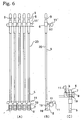
- each one of the unit fastening elements 20 is shown in Fig. 6.
- each one of the unit fastening element 20 comprises a filament section 5 that forms a loop by passing the tag, an inserting head section 6 mounted on one end of the filament section and equipped with an appropriate step like or a hooked portion 9, and a socket section 8 mounted on the other end of the filament section 5 and provided with a hole 7 for passing the inserting head section 6 and being provided with a blade member 19 therein, the blade member 19 being enable to engage with the step-like portion 9 of the inserting head section 6 so as to irreversibly fix the inserting head section 6 in the hole 7.
- An embodiment of the fastening element 4 as shown in FIG. 5, is formed integral preferably with synthetic resin, etc., and in particular, the filament section 5 is drawn and is extremely resistant to tension.
- these fastening elements 4 are loaded on the special-purpose coupler gun (attaching gun) 10 as shown in Fig. 7, and have been used not only for binding boots, sandals, or shoes but also primarily for fixing the brand label or tag T describing the directions for use to products by using an operation lever.
- the fastening element including the filament sections is simply formed in a flat surface configuration, and thus when the fastening element 4 is mounted on the attaching gun 10, it is necessary for an operator to bend the filament section 5 by hands so that the inserting head section 6 and the socket section 8 are closed to each other, and such operation arises various difficulties for the operator.
- the fastening element 4 when the fastening element 4 is mounted on the attaching gun 10 enabling to fasten a label, a tag or the like to a good, by operating the lever 18 of the attaching gun 10 so that a plurality of the unit fastening elements 20 is continuously attached to each one of predetermined goods, respectively, the operator is required to do operations in which the fastening element 4 is first bent with a relatively large force and then the connection bar 11' to which the inserting head sections 6 are connected, is inserted into an insertion slit 31 mainly used for the connection bar 11', after that, the connection bar 11 to which the socket sections 8 are connected, is inserted into an insertion slit 32 mainly used for the connection bar 11.
- connection bar inserting operation is usually very heavy work and further it is also difficult operation in which the operator holds the attaching gun 10 with his one hand while sets the fastening element 4 on the gun 10 with his another hand.
- the fastening element 5 since it is difficult to identify a front surface or a back surface of the fastening element 5 when the filament sections of the fastening element 5 having a flat configuration should be bent, the fastening element 5 is sometimes erroneously bent in an opposite direction, causing the attaching gun 10 into malfunction.
- a plurality of the fastening element 4 as shown in Fig. 5, are stacked with each other and inserted into a predetermined package with this stacked condition.
- each one of the filament sections 5 of one fastening element 4 are entangled with the inserting head section 6 or he socket section 8 of other fastening element 4 adjacently arranged thereto and thus when one fastening element 4 is about to be picked up from the package, a plurality of other fastening elements 4 are simultaneously withdrawn from the package and thus a significant extra operation is required to separate them each other causing the operation cost to be increased.
- a curve-like portion 34 or a folded portion 35 is positively formed or a portion 36 which can be easily bent or a portion 36 which can be easily folded is also positively formed thereat.
- the operation for mounting the fastening element 4 on the attaching gun 10 as shown in Fig. 7, has been improved but however, a distance formed between the curve-like portion 34 or the folded portion 35 of one filament section 5 of the fastening element 4 and that of another filament section 5 adjacently arranged thereto, is easily changed and thus it is acknowledged that during a time when each one of the unit fastening elements mounted on the attaching gun 10 is shot successively, the filament sections 5 adjacently arranged to each other are entangled with each other causing to generate the jamming condition.
- Yet another object of the present invention is to provide a method for producing a fastening element of the kind.
- the present invention basically adopts the configuration as recited below. That is, the first aspect of the present invention relates to a fastening element comprising a plurality of a unit fastening element arranged adjacently and in parallelism with each other, each of the unit fastening elements comprising a filament section, an inserting head section equipped with a suitable engagement section located at one end of the filament section, and a socket section equipped with a hole for irreversibly passing the inserting head section located at the other end of the filament section, wherein a plurality of the socket sections or their vicinities each being adjacently arranged to each other and a plurality of the inserting head sections or their vicinities each being adjacently arranged to each other, are temporarily and individually connected to each one of connection bars, respectively, and further each of the connection bars are closely arranged to each other so as to be oppositely disposed to each other, the filament section of each one of the unit fastening elements being formed in curved configuration which is in fixed condition
- the second aspect of the present invention relates to a package for containing fastening elements as defined by claim 13.
- the third aspect of the present invention relates to a method for producing a fastening element as defined by claim 15.
- the fastening element according to the present invention is characterized in that a fastening element comprising a plurality of unit fastening elements arranged adjacently and in parallelism with each other, each of the unit fastening elements comprising a filament section, an inserting head section equipped with a suitable engagement section located at one end of the filament section, and a socket section equipped with a hole for irreversibly passing the inserting head section located at the other end of the filament section, a plurality of the socket sections or their vicinities each being adjacently arranged to each other and a plurality of the inserting head sections or their vicinities each being adjacently arranged to each other, are temporarily and individually connected to each one of connection bars, respectively, and further each of the connection bars are closely arranged to each other so as to be oppositely disposed to each other with a predetermined length displaced to each other along a longitudinal direction of the both connection bars and further the filament section of each one of the unit fastening elements being formed in curved configuration which is in fixed condition.
- the fastening element of the present invention is preferably configured so that a flat surface formed by each one of the curved configuration of each one of the filament sections is set either substantially in parallelism with the longitudinal direction of the both connection bars or with a predetermined angle with the longitudinal direction thereof.
- the fastening element of the present invention is further preferably configured so that at least a part of the curved configuration formed by each one of the filament sections is overlapped with at least a part of the curved configuration of other filament section adjacently arranged thereto each other.
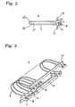
- FIG. 1 is a view showing a configuration of one example of the fastening element according to the present invention.
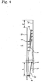
- a fastening element 4 comprising a plurality of a unit fastening elements 20 arranged so that each one of the filament sections 5 being adjacently and in parallelism with each other, each of the unit fastening elements 20 comprising a filament section 5, an inserting head section 6 equipped with a suitable engagement section located at one end of the filament section 5, and a socket section 8 equipped with a hole 7 for irreversibly passing the inserting head section 6 located at the other end of the filament section 5, the fastening element 4, a plurality of the socket sections 8 or their vicinities each being adjacently arranged to each other and a plurality of the inserting head sections 6 or their vicinities each being adjacently arranged to each other, are temporarily and individually connected to each one of connection bars 11 and 11', respectively, and further each of the connection bars 11 and 11' are closely arranged to each other so as to be oppositely disposed to each other with a predetermined length displaced to each other along a longitudinal direction of the both connection bars 11 and 11' and
- fastening element 4 of the present invention is, as shown in Fig. 4, such that a flat surface 22 formed by each one of the curved configuration 21 of each one of the filament sections 5 is set either substantially in parallelism with the longitudinal direction of the both connection bars 11 and 11' or with a predetermined angle with the longitudinal direction thereof.
- the curved portion 21 of each one of the filament sections 5 consisting the fastening element 4 of the present invention is preferably heat-set but it may be set in this predetermined configuration with utilizing an appropriate fixing substance.
- the filament section 5 of the present invention may be pressed by pressing the filament section 5 into a predetermined shape and by pressing it for a long time with keeping its configuration.
- another method can also be used in which after the filament section 5 is molded with drawing the same and during a time in which the filament section 5 has not yet been completely cooled, that is during a time in which the filament section 5 is still in a thermoplastic condition, after the both of the connection bars 11 and 11' being oppositely disposed to each other, are displaced with a predetermined length to each other along a longitudinal direction of the both connection bars 11 and 11', an appropriate pressing treatment is applied to the fastening element 5 so as to change each one of the filament sections 5 into a flat and curved form.
- the filament section 5 is preferably made of a synthetic material which can be set with heat.
- the fastening element 4 according to the present invention may be formed integral by nylon, polypropylene, polyester, or other synthetic resins, as the conventional fastening element.
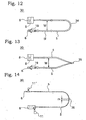
- a method for heating set the filament section 5 is not specifically restricted to that as mentioned above, but it may be a method as shown in Figs. 10 and 11, in which the filament section 5 can be treated with a pressing operation utilizing a pressing plates heated at an appropriate temperature or a method in which the filament section 5 can be treated with a pressing operation utilizing pressing plates which are not directly heated but the filament section 5 is heated with applying a heated air, an infrared beam or laser right beam thereto so that the filament section 5 becomes into a thermoplastic condition under which the filament section 5 is pressed.
- an amount of a displacing distance L formed between the connection bars 11, 11' which are displaced along the longitudinal direction thereof each other is not restricted to a specific value, but it can be set within a range of 5 to 30 mm and preferably within a range of 10 to 20 mm.
- a range of the amount of a displacing distance L formed between the connection bars 11, 11' is preferably set at a necessary length with respect to a material to be used for the fastening element 4 or a length of the filament section 5.
- connection bars 11 and 11' of the fastening element 4 each being oppositely arranged to each other, are able to maintain a stable and parallel condition under which both bars being overlapped with each other, and further, it is also possible that the filament section 5 of one fastening element 4 can maintain its stable condition with closely contacting with another filament section 5 of a separate fastening element 4 adjacently arranged to the fastening element.
- connection bars 11 and 11' are not set in parallelism with each other so that the bars show a something like a twisted condition and thus it becomes impossible to mount the fastening element 4 on the attaching gun 10.
- connection bars 11 and 11' are held in vertical direction, the most lowest end portion of one of the connection bars is put on a position below a position of the most lowest end portion of another connection bar.
- a first guide portion 40 is provided at least at one end portion of the connection bar 11' to which a plurality of the inserting head sections 6 are connected, the first guide portion 40 having a predetermined length and to which none of the inserting head section 6 is connected.
- connection bar 11 to which a plurality of the socket sections 8 are connected is provided with a second guide portion 41 having a predetermined length shorter than that of the first guide portion 40, and to which none of the socket section 8 is connected, at least at one end portion thereof or the connection bar 11 is not provided with the above-mentioned second guide portion 41 at least at one end portion thereof.
- a position 24 of the most lowest end portion of the first guide portion 40 of the connection bar 11' to which the inserting head section 6 are connected is preferably set at a position located below the most lowest end portion 25 of the second guide portion 41 of the first connection bar 11 to which the socket sections 8 are connected, by a length of l, or in a case in which no second guide portion 41 is provided, a position 24 of the most lowest end portion of the first guide portion 40 is preferably set at a position located below the most lowest end portion 25 of the first connection bar by a length of 1.
- the position 24 of the most lowest end portion of the second connection bar 11' to which the inserting head section 6 are connected is set at a position below the most lowest end portion 25 of the first connection bar 11 to which the socket sections 8 are connected.
- connection bars 11 and 11' of the fastening element 4 are provided on the connection bars 11 and 11' of the fastening element 4, respectively, the first connection bar 11 to which the socket sections 8 are connected, and the second connection bar 11' to which the inserting head sections 6 are connected, are surely inserted into each one of the connection bar insertion slits 31 and 32 into which each one of the connection bars should be inserted, respectively.
- connection bar is the connection bar to which the socket sections 8 are connected or which connection bar is the connection bar to which the inserting head sections 6 are connected, and accordingly, an occasion at which an insertion mistake is generated, will be surely avoided.
- a guide portion 40 is provided on the connection barn 11' to which the inserting head sections 6 are connected, by extending an lower end portion of the connection bar 11', downwardly from a position of the connection bar 11' at which the most lowest inserting head section 6 of an array of a plurality of inserting head sections 6, is disposed on the connection bar 11', with an appropriate length.
- connection bars 11 and 11' that are another end portions of each one of the connection bars 11 and 11', which being opposite to each one of the end portions of the connection bars 11 and 11' and each being provided with the guide portions 40 and 41, respectively, no extended portion as mentioned above is provided and a position of the end portion of each one of the connection bars should be disposed closely adjacent to a position at which the inserting head section 6 locating at the most end portion in the allay of the inserting head sections 6, or the socket section 8 locating at the most end portion in the array of socket sections 8, is disposed.
- connection bars 11 or 11' of the fastening element 4 By using this configuration as mentioned above, it becomes possible that an operator can easily decide which end portion of one of the connection bars 11 or 11' of the fastening element 4, should be inserted into which one of the connection bar inserting slits 31 or 32 formed on the attaching gun 10 and accordingly, the working efficiency thereof is improved as well as the generations of malfunctions of the attaching gun 10 due to such insertion mistake of the connection bar or the generations of jamming are significantly reduced.
- the fastening element 4 of the present invention it is also preferable that at least one of an external configuration, a length, an cross-sectional configuration, a color of the second connection bar 11' to which a plurality of the inserting head sections 6 are connected, or the guide portion 40 of the second connection bar 11' is different from that of the first connection bar 11 to which a plurality of the socket sections 8 are connected or the guide portion 41 of the first connection bar 11.
- the fastening element 4 of the present invention is especially effective when it is used with an attaching gun for shooting each one of the unit fastening elements against a good or a product, which is disclosed in the specification of the Japanese Patent Application Number 2000-131967 for which the inventor of the present invention is one of the co-inventors.
- the flat portion 30 of the present invention can show a rigid condition with keeping each one of the filament sections 5 in an independent and easily separable condition from other filament sections 5 being adjacently arranged thereto.
- the direction for bending it is also possible to be a direction so that the connection bars 11 and 11' are located inside the curved configuration but in the preferable embodiment, the socket sections and the inserting head sections are sandwiched between the first and second connection bars each being oppositely arranged to each other, in the curved filament section 5.
- a distance formed between side wall portions of two socket sections 8 each being adjacently arranged to each other should preferably be set at a width shorter than the most smallest diameter of each one of the inserting head section 6.
- the fastening element 4 having the above-mentioned configuration, it is possible to provide a package 50 for containing the fastening elements 4 in which a plurality of the fastening elements 4 are contained therein so that a plurality of the fastening elements 4 are stacked one on other or adjacently arranged in contacting condition to each other with a condition in that the connection bars 11 and 11' of each one of the fastening elements 4 are arranged in parallelism with those of another fastening element adjacently arranged thereto.
- the fastening elements 4 of the present invention as shown in Fig. 1 and the conventional fastening element 4 as shown in Fig. 5 each being make of the same material and having the same dimension and same pitch as each other.
- each one of the operators had also tried to shoot the respective 50 numbers of the unit fastening elements 20 which are fixed by both connection bars to form a configuration as shown in Fig. 5, but further each of the filament sections having a curved configuration so as to be shown in Fig. 1 (referred to "a curved pin” in Table 1), three times, so that each operator had shot total of 300 of the unit fastening elements, respectively.
- the Table 1 shows a result of an analysis about problems as appeared by these experiments.
- the data as shown in the column labeled by the term of "a straight pin” and "a curved pin” means that the results of the test in which the successive shooting operation for 50 numbers of the straight pins followed by the successive shooting operation for 50 numbers of the curved pins so that the successive shots for the 50 of straight pins and the successive shots for the 50 of the curved pins are carried out, alternatively.
- the term of "entanglement” denotes a condition in which when the fastening element is mounted on the attaching gun and the shooting operation for each one of the unit fastening elements is carried out, a filament section of one of the unit fastening element of one fastening element is entangled with one or a plurality of the filament sections of the unit fastening elements of the separate fastening element being adjacently arranged thereto so that the shooting operation to shot the unit fastening element becomes impossible or a condition in that separate operation for taking out from the attaching gun, the unit fastening element which is failed to be shot out therefrom, should be done.
- the term of "Incomplete coupling” denotes a condition in which, although an operation lever of the attaching gun had been actuated, the inserting head section 6 cannot be coupled with the socket section 8 due to the inserting head section 6 being displaced out of its original passage.
- the term of "lack of gripping” denotes a condition in which due to the working lever of the attaching gun not having been completely pushed to the final destined position thereof, the inserting head section 6 cannot completely be coupled with the socket section 8 so that incomplete transfer of the unit fastening element, had been occurred.
- the term of" Incomplete set denotes the condition in which after when the above-mentioned problems have been occurred and when the fastening element is reset to be mounted on the attaching gun, the resetting operation had not been done correctly, (especially on a side for the inserting head section), so that the inserting head section 6 and the socket section 8 cannot completely be coupled with each other.
- a plurality of the fastening element which have been produced in a factory are contained into an appropriate containers or packages and shipped and transferred therefrom to a field site at which each one of the unit fastening elements is shot so as to be attached to a prescribed product or good with a prescribed label.
- each one of operators takes up each one of the fastening elements from the prescribed container or package, one by one so that the mounting operation for mounting the fastening element on the attaching gun, is carried out.
- the fastening element 4 since the fastening element 4 has an approximately flat configuration, even when a plurality of the fastening elements 4 are inserted into a package 50 for the fastening elements with a stacked formation or with an arbitrary formation, they can be easily contained without showing a bulked condition and thus they can be easily contained or kept inside the container or package 50.
- the fastening element 4 among a plurality of the filament sections 5 forming a part of the fastening element 4, no other filament section 5 of another fastening element 4 can be inserted thereinto or none of the inserting head section 6 or the socket section 8 of one of the fastening element 4, can be entangled with a filament section 5 of another fastening element 4, even when a plurality of the fastening elements 4 are held inside the container in a form of an appropriate stacked formation or the like, no entanglement among the filament section would be raised between the filament sections or between the filament section and either one of the inserting head section 6 or the socket section 8, would have been occurred in the package.
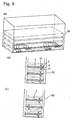
- a package 50 is a container having a vertical type main body and in that a plurality of the fastening element 4 are stacked inside the package in a laterally arranged formation with both of the connection bars 11 and 11' being arranged in parallelism with each other.
- a cartridge-type package having a rectangular form with a narrow width can be conveniently used.
- a plurality of fastening elements 4 are kept inside a prescribed package 50, as shown in the Fig. 8(B), it is possible to insert the plurality of fastening elements 4 into the package 50 by adjusting an inserting direction thereof so that a connection bar 11 of one of the fastening elements 4 is overlapped with or is closely arranged to other connection bar 11 of a separate fastening elements 4' adjacently arranged thereto.
- connection bar 11 of one of the fastening element 4 is arranged at a position opposite to a position at which another connection bar 11 of a separate fastening element 4' adjacently arranged thereto, is arranged, in an alternate configuration, for example, with one by one formation or with another formation in that a group of a prescribed number of fastening elements and another group of a prescribed number of fastening elements which is the same as or different from that of the former group, are alternatively arranged.
- the package for the fastening elements should be made so that a position at which the connection bar 11 of the first fastening element is disposed, is different from a position at which the connection bar 11 of the second fastening element being different from the first fastening element, is disposed.
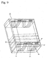
- Fig. 9 shows a separate configuration of the package 51 for the fastening element as another embodiment of the package therefor.
- the package 51 for the fastening element is a vertical typed package therefor, and thus a plurality of fastening elements 4 are inserted into this package 51 vertically in upright configuration with their connection bars 11 and 11' arranged in parallelism with each other.
- the package for the fastening elements should be made so that a position at which the connection bar 11 of the first fastening element is disposed, is different from a position at which the connection bar 11 of the second fastening element being different from the first fastening element, is disposed or the package for the fastening elements should be made so that a position at which the connection bar 11 of the first fastening element is disposed, is set at the same position at which the connection bar 11 of the second fastening element being different from the first fastening element, is disposed.
- the package can be attached to a belt or the like of an operator and each one of the fastening element 4 can be taken out easily from the package 50 or 51 at a field site depending upon its necessity by hand of the operator and it can be easily mounted on the attaching gun or the like.
- the fastening element 4 of the present invention since it is possible to completely eliminate the generation of troubles in that the inserting head section 6 or the socket section 8 of one of the fastening element 4 are prevented from being inserted into among the filament sections 5 of another fastening element 4 which is adjacently arranged thereto so as to generate such entanglement therebetween, as mentioned above, even when a plurality of the fastening elements are contained in a package either in an arbitrary condition, for example, in a stacked condition or in a vertical side by side arrangement condition, a desired fastening element can be easily and smoothly singled out among the plurality of fastening elements contained therein, without any entanglement therebetween.
- the operation for mounting each one of the fastening elements on the attaching gun 10 becomes very easy for an operator as well as a size of the package for containing or storing a plurality of the fastening elements can be minimized so that a space for storing such packages or for wrapping the packages can be remarkably reduced causing the cost therefor to be reduced.
- the following method can be preferably used.
- such method is a method for producing a fastening element comprising a plurality of unit fastening elements arranged adjacently and in parallelism with each other, each of the unit fastening elements comprising a filament section, an inserting head section equipped with a suitable engagement section located at one end of the filament section, and a socket section equipped with a hole for irreversibly passing the inserting head section located at the other end of the filament section, a plurality of the socket sections or their vicinities each being adjacently arranged to each other and a plurality of the inserting head sections or their vicinities each being adjacently arranged to each other, are temporarily and individually connected to each one of connection bars, respectively, wherein the method comprising; arranging each of the connection bars closely to each other so as to be oppositely disposed to each other with a predetermined length displaced to each other along a longitudinal direction of the both connection bars; and applying a fixing treatment to each one of the unit filament sections of the respective fastening element with a compression force so that a flat surface
- the heat set treatment is not restricted to a specific treatment but it may preferably be a heat set treatment for one example, and be a method for reducing the filament section into a curved configuration with an appropriate fixing substance, for another example.
- the method comprises the steps of;
- the heat setting operation for the curved filament section 5 is not restricted only to the dry heat setting method but wet heat setting method can also be used.
- the configuration of the flattened filament section 5 of the fastening element 4 can be set as it is by heating and pressing the flattened filament section 5 by an appropriate heating members.
- this embodiment is basically identical to the above-mentioned embodiment of the present invention in the basic configuration thereof and the basic method for producing the questioned fastening element 4.
- the above-mentioned embodiments is mainly focus on the fastening element 4 which can be used with a specially designed attaching gun 10, mechanically.
- connection bars 11 and 11 are relatively hard and rigid so as to keep its configuration on the attaching gun 10 and also the connecting portions 60 and 61 formed between each one of the connection bars and each one of the inserting head sections6 or socket sections 8, are hard and strong so as to be separated by a cutter provided on the attaching gun 10.
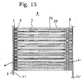
- the separate embodiment of the present invention as shown in Figs. 15 to 17 provides a fastening element 4 which can be used by an operator with his hands and thus each one of the unit fastening elements 6 can be separated from the connection bars, easily by hands of the operator.
- each one of the connection bars 11 and 11' is made of a filament like fine member and each one of the inserting head sections 6 and the socket sections 8 are easily and separably connected to either one of the connection bars 11 and 11', respectively, by hand.
- connection bars 11 is connected to each one of the outer most end portion 70 of the inserting head sections 6 of the filament sections 5 each forming the fastening element 4, while another connection bars 11' is connected to each one of the outer most end portion 71 of the socket sections 8 of the filament sections 5 each forming the fastening element 4.
- the socket sections6 and the inserting head sections 8 are closely and adjacently arranged with each other as well as the connection bars 11 and 11' are directly facing to and adjacently arranged with each other through each one of the curved filament sections 5.
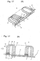
- FIG. 17 a perspective configuration of this embodiment of the present invention is shown in Fig. 17.
- connection bars 11 and 11' is somewhat soft and weak comparing that of the above mentioned embodiments of the present invention, so as to enable to be contained much more numbers of the fastening element 4 in a package having a restricted capacitor.
- connecting portions 60 are integrally formed with the inserting head sections 6 and the connection bar 11 and the connecting portions 61 are integrally formed with the socket sections 8 and the connection bar 11', respectively with one molding operation of the fastening element 4.
- the connecting portions 60 and 61 have a strength so as not to be broken under forces generated during the time when the fastening element 4 is produced, is transferred, is taken up from a package or is mounted on the attaching gun but so as to be easily broken by a hand work of an operator.
- the operator will work to separate one of the filament section 6 from the fastening element 4 and pass one of the ends portion of this filament section 5 through a good with tag or label and will couple the inserting head section 6 with the socket section 8 with his hands. Since the present invention adopts the configurations as described above, the present invention is able to provide various remarkable operational effects.
- each one of the filament sections 5 is previously bent, when it is mounted on an appropriate attaching gun which is a device being able to continuously couple the fastening element with a good by pulling a operation lever, the mounting operation or setting operation of the fastening element becomes very easy due to no specific bending or curving operation being required to match the fastening element to a configuration of such gun.
- the filament sections of the fastening element had already bent, it is possible to minimize a size in width direction of the attaching gun and in addition thereto, the occasion in that the above-mentioned jamming would be generated can be remarkably reduced.
- the fastening element in the conventional flat type fastening element, an operator should mount the fastening element on the attaching gun mainly used for this fastening element with simultaneously performing the bending operation on the flat type fastening element causing the mounting operation to be complicated, however, in the present invention, the fastening element can simply be mounted on the attaching gun as it is without doing any other operation.
- the generation of entangled condition among the filament sections is completely prevented and when the fastening element had been mounted on the attaching gun, the shooting operation for shooting each one of the unit fastening elements can also be performed smoothly so that the generation of the jamming condition can also be prevented, previously.
- the fastening element of the present invention since it is possible to completely eliminate the generation of troubles in that the inserting head section 6 or the socket section 8 of one of the fastening element 4 are prevented from being inserted into among the filament sections 5 of another fastening element 4 which is adjacently arranged thereto so as to generate such entanglement therebetween, as mentioned above, even when a plurality of the fastening element are contained in a package either in an arbitrary condition, for example, in a stacked condition or in a vertical side by side arrangement condition, a desired fastening element can be easily and smoothly singled out among the plurality of the fastening elements contained therein, without any entanglement therebetween.
- the operation for mounting each one of the fastening elements on the attaching gun 10 becomes very easy for an operator as well as a size of the package for containing or storing a plurality of the fastening elements can be minimized so that a space for storing such packages or for wrapping the packages can be remarkably reduced causing the cost therefor to be reduced.
Landscapes
- Engineering & Computer Science (AREA)
- Physics & Mathematics (AREA)
- General Physics & Mathematics (AREA)
- Theoretical Computer Science (AREA)
- Mechanical Engineering (AREA)
- Computer Security & Cryptography (AREA)
- Labeling Devices (AREA)
- Mutual Connection Of Rods And Tubes (AREA)
- Slide Fasteners, Snap Fasteners, And Hook Fasteners (AREA)
- Packaging Of Annular Or Rod-Shaped Articles, Wearing Apparel, Cassettes, Or The Like (AREA)
- Package Closures (AREA)
- Massaging Devices (AREA)
- Bolts, Nuts, And Washers (AREA)
Claims (21)
- Elément de fixation (4) comprenant une pluralité d'éléments de fixation d'une unité (20) agencée de manière adjacente et parallèle les uns aux autres, chaque élément de fixation de l'unité (20) comprenant une section en filament (5), une section de tête d'insertion (6) équipée d'une section d'engagement appropriée située au niveau d'une extrémité de la section en filament (5) et une section à douille (8) pourvue d'un orifice (7) pour faire passer de manière irréversible ladite section de tête d'insertion (6) située au niveau de l'autre extrémité de ladite section en filament, dans lequel une pluralité desdites sections à douille (8) ou leurs proximités, agencées de manière adjacente les unes par rapport aux autres, et une pluralité desdites sections de tête d'insertion (6) ou leurs proximités, agencées de manière adjacente les unes par rapport aux autres, sont reliées de manière temporaire et individuelles à chacune des barres de connexion (11, 11'), respectivement, et toutes lesdites barres de connexion sont en outre agencées l'une par rapport à l'autre de façon à être disposées de manière opposée l'une à l'autre, ladite section en filament (5) de chacun desdits éléments de fixation d'unité (20) étant formé dans une configuration courbée (21) qui est dans une condition fixée, caractérisé en ce que lesdites barres de connexion (11, 11') sont déplacées l'une par rapport à l'autre selon une longueur prédéterminée (L) le long d'une direction longitudinale desdites deux barres de connexion.
- Elément de fixation selon la revendication 1, dans lequel une surface plate (22) formée par chacune desdites configurations courbée (21) de chacune desdites section en filament est établie sensiblement de manière parallèle à ladite direction longitudinale desdites deux barres de connexion (11, 11') ou selon un angle prédéterminé par rapport à ladite direction longitudinales de celles-ci.
- Elément de fixation selon la revendication 1 ou 2, dans lequel chacune desdites sections en filament (5) est thermofixée.
- Elément de fixation selon l'une quelconque des revendications 1 à 3, dans lequel ladite section en filament (5) est réalisée à partir d'un matériau synthétique qui peut être fixé avec de la chaleur.
- Elément de fixation selon l'une quelconque des revendications 1 à 4, dans lequel, quand lesdites deux barres de connexion (11, 11') sont maintenues suivant une direction verticale, la partie d'extrémité la plus inférieure (24) d'une desdites barres de connexion (11') est placée sur une position au-dessous d'une position de la partie d'extrémité la plus inférieure (25) de l'autre barre de connexion (11).
- Elément de fixation selon l'une quelconque des revendications 1 à 5, dans lequel une première partie de guidage (40) est fournie au moins au niveau d'une partie d'extrémité de ladite barre de connexion (11') à laquelle est reliée une pluralité desdites sections de tête d'insertion (6), ladite première partie de guidage (40) ayant une longueur prédéterminée à laquelle aucune desdites section de tête d'insertion n'est reliée.
- Elément de fixation selon la revendication 6, dans lequel ladite barre de connexion (11) à laquelle est reliée une pluralité desdites sections à douille (8) est pourvue d'une seconde partie de guidage (41) ayant une longueur prédéterminée plus courte que celle de ladite première partie de guidage (40) et à laquelle aucune desdites section à douille n'est reliée.
- Elément de fixation selon la revendication 6 ou 7, dans lequel, quand lesdites deux barres de connexion (11, 11') sont maintenues dans la direction verticale de sorte que ladite première partie de guidage (40) soit dirigée vers le bas, ladite partie d'extrémité la plus inférieure (24) de ladite première partie de guidage (40) d'une seconde barre de connexion (11') à laquelle est reliée une pluralité desdites sections de tête d'insertion (6), est placée sur une position identique à une position de ladite partie d'extrémité la plus inférieure (25) de ladite seconde partie de guidage (41) d'une première barre de connexion (11) à laquelle est reliée une pluralité desdites sections à douille (8), ou au-dessous d'une position de ladite partie d'extrémité la plus inférieure (25) de ladite première barre de connexion (11).
- Elément de fixation selon l'une quelconque des revendications 1 à 8, dans lequel au moins une partie de ladite configuration courbée (21) de chacune des sections en filament (5) est chevauchée par au moins une partie de ladite configuration courbée d'une autre section en filament agencée de manière adjacente l'une par rapport à l'autre.
- Elément de fixation (4) selon la revendication 9, dans lequel ledit élément est pourvu d'une partie plate formée par une pluralité desdites configurations courbées (21) de chacune desdites sections en filament (5), au moins une partie de celles-ci étant partiellement en chevauchement les unes par rapport aux autres.
- Elément de fixation selon l'une quelconque des revendications 1 à 10, dans lequel lesdites sections à douille (8) et lesdites sections de tête d'insertion (6) sont intercalées entre lesdites première et seconde barres de connexion (11, 11') chacune étant agencée de manière opposée par rapport à l'autre.
- Elément de fixation selon l'une quelconque des revendications 7 à 11, dans lequel au moins un élément parmi une configuration externe, une configuration en coupe transversale et une couleur de ladite seconde barre de connexion (11') à laquelle est reliée une pluralité desdites sections de tête d'insertion (6) ou une longueur de ladite première partie de guidage (40) de ladite seconde barre de connexion (11') est différente de celle de ladite première barre de connexion (11) à laquelle est reliée une pluralité desdites sections à douille (8).
- Paquet (50) destiné à contenir des éléments de fixation dans lequel une pluralité desdits éléments de fixation (4), selon l'une quelconque des revendications 1 à 12, est contenue dans celui-ci de sorte qu'une pluralité desdits éléments de fixation soit empilée, les uns sur les autres, ou agencée de manière adjacente dans une condition en contact les uns par rapport aux autres, moyennant quoi chacun desdits éléments de fixation (4) entre en contact avec un autre élément de fixation avec une condition où lesdites barres de connexion (11, 11') de chacun desdits éléments de fixation sont agencées de manière parallèle à celles d'un autre élément de fixation agencé de manière adjacente.
- Paquet destiné à contenir des éléments de fixation selon la revendication 13, dans lequel parmi une pluralité desdits éléments de fixation (4), chacun étant attaché de manière adjacente à un autre, une position selon laquelle sont disposées lesdites barres de connexion (11, 11') d'un premier élément de fixation est différente d'une position selon laquelle sont disposées lesdites barres de connexion d'un second élément de fixation différent dudit premier élément de fixation.
- Procédé de production d'un élément de fixation (4) comprenant une pluralité d'éléments de fixation d'une unité (20) agencée de manière adjacente et parallèles les uns par rapport aux autres, chacun desdits éléments de fixation de l'unité comprenant une section en filament (5), une section de tête d'insertion (6) équipée d'une section d'engagement approprié située au niveau d'une extrémité de ladite section en filament et une section à douille (8) pourvue d'un orifice (7) pour faire passer de manière irréversible ladite section de tête d'insertion (6) située au niveau de ladite autre extrémité de ladite section en filament (5), dans lequel une pluralité desdites sections à douille (8) ou leurs proximités, agencées de manière adjacente les unes par rapport aux autres, et une pluralité desdites sections de tête d'insertion (6) ou leurs proximités, agencées de manière adjacente les unes par rapport aux autres, sont reliées les unes aux autres de manière temporaire et individuelle à chacune des barres de connexion (11, 11'), respectivement, dans lequel ledit procédé comprend les étapes consistant à :agencer chacune desdites barres de connexion de manière serrée l'une par rapport à l'autre de façon à ce qu'elles soient disposées de manière opposée l'une à l'autre selon une longueur prédéterminée (L) de déplacement l'une par rapport à l'autre le long d'une direction longitudinale desdites deux barres de connexion (11, 11') ; etappliquer un traitement de fixation à chacune desdites sections en filament d'unité (5) de l'élément de fixation respectif formé dans une configuration courbée avec une force de compression.
- Procédé de production d'un élément de fixation selon la revendication 15, dans lequel ledit traitement de fixation avec ladite force de compression est réalisé de sorte qu'une surface plate (22) formée par chacune desdites configurations courbées (21) de chacune desdites sections en filament (5) soit établie de manière sensiblement en parallèle à la direction longitudinale desdites deux barres de connexion (11, 11') ou selon un angle prédéterminé par rapport à la direction longitudinale de celles-ci.
- Procédé de production d'un élément de fixation (4) selon la revendication 15 ou 16, dans lequel ledit traitement de fixation est un traitement de fixage thermique.
- Procédé de production d'un élément de fixation selon l'une quelconque des revendications 15 à 17, dans lequel au moins une partie de ladite configuration courbée (21) de chacune desdites sections en filament (5) est chevauchée par au moins une partie de ladite configuration courbée d'une autre section en filament agencée de manière adjacente à celle-ci.
- Elément de fixation (4) selon l'une quelconque des revendications 1 à 12, dans lequel, chacune desdites barres de connexion (11, 11') est réalisée à partir d'un élément fin similaire à un filament et chacune desdites sections de tête d'insertion et desdites sections à douille sont reliées de manière facile à l'une des deux barres de connexion de façon à pouvoir en être séparée, respectivement, à la main.
- Elément de fixation selon la revendication 19, dans lequel une desdites barres de connexion est reliée à chaque partie d'extrémité la plus externe desdites sections de tête d'insertion (6) des sections en filament (5), formant chacune ledit élément de fixation, alors que l'autre barre de connexion est reliée à chaque partie d'extrémité la plus externe desdites sections à douille (8) des sections en filament formant chacune ledit élément de fixation.
- Elément de fixation selon les revendications 19 et 20, dans lequel lesdites sections à douille (8) et lesdites sections de tête d'insertion (6) sont agencées de manière serrée et adjacentes les unes aux autres alors que lesdites barres de connexion (11, 11') sont agencées de manière adjacente et dans une relation en face à face l'une par rapport à l'autre à travers chacune desdites sections en filament courbées (5).
Applications Claiming Priority (2)
| Application Number | Priority Date | Filing Date | Title |
|---|---|---|---|
| JP2002009874 | 2002-01-18 | ||
| JP2002009874A JP4100917B2 (ja) | 2002-01-18 | 2002-01-18 | 封緘具 |
Publications (2)
| Publication Number | Publication Date |
|---|---|
| EP1329867A1 EP1329867A1 (fr) | 2003-07-23 |
| EP1329867B1 true EP1329867B1 (fr) | 2006-08-23 |
Family
ID=19191547
Family Applications (1)
| Application Number | Title | Priority Date | Filing Date |
|---|---|---|---|
| EP03250317A Expired - Lifetime EP1329867B1 (fr) | 2002-01-18 | 2003-01-17 | Elément de fixation |
Country Status (8)
| Country | Link |
|---|---|
| US (1) | US6848575B2 (fr) |
| EP (1) | EP1329867B1 (fr) |
| JP (1) | JP4100917B2 (fr) |
| KR (1) | KR100526263B1 (fr) |
| CN (1) | CN1177739C (fr) |
| AT (1) | ATE337596T1 (fr) |
| DE (1) | DE60307689T2 (fr) |
| TW (1) | TW593076B (fr) |
Families Citing this family (10)
| Publication number | Priority date | Publication date | Assignee | Title |
|---|---|---|---|---|
| JP4638156B2 (ja) * | 2004-01-21 | 2011-02-23 | 有限会社エムアイティインターナショナル | ループピン結合装置 |
| USD514425S1 (en) | 2004-05-27 | 2006-02-07 | Brammall, Inc. | Locking device |
| US20060042051A1 (en) * | 2004-08-27 | 2006-03-02 | Irwin Jere F | Strips of clips and clip |
| US20060266087A1 (en) * | 2004-11-12 | 2006-11-30 | Hamilton Eric K | Locking device |
| JP2010126176A (ja) * | 2008-11-26 | 2010-06-10 | Kotecs Co Ltd | ループピン結合装置及びループピン打ち出し方法 |
| JP2010280410A (ja) * | 2009-06-04 | 2010-12-16 | M I T Internatl:Kk | ループピン |
| CH701845B1 (de) * | 2009-09-22 | 2014-03-14 | Chrisofix Ag | Fixierelement sowie Verwendung eines solchen Fixierelements zum Fixieren eines Gegenstandes, insbesondere von Gliedmassen. |
| US10510273B2 (en) * | 2015-06-04 | 2019-12-17 | Avery Dennison Corporation | Plastic fastener and plastic fastener assembly |
| CN109835619B (zh) * | 2017-12-21 | 2020-08-18 | 王博 | 一种三色签益智游戏盒 |
| WO2019178014A1 (fr) * | 2018-03-14 | 2019-09-19 | Avery Dennison Corporation | Pince d'attache |
Family Cites Families (5)
| Publication number | Priority date | Publication date | Assignee | Title |
|---|---|---|---|---|
| ZA786960B (en) * | 1977-12-15 | 1979-11-28 | L Dore | Improvements in or relating to tags and applicators therefor |
| JPH10116034A (ja) * | 1996-10-14 | 1998-05-06 | J Ii Kk | タグ吊持用のフレキシブルピン材 |
| JP2000238714A (ja) * | 1999-02-18 | 2000-09-05 | Kotecs Co Ltd | 封緘具 |
| JP2001056644A (ja) * | 1999-08-18 | 2001-02-27 | Je Kk | 封緘具 |
| JP2001261018A (ja) * | 2000-03-21 | 2001-09-26 | Kotecs Co Ltd | 封緘具 |
-
2002
- 2002-01-18 JP JP2002009874A patent/JP4100917B2/ja not_active Expired - Lifetime
-
2003
- 2003-01-17 AT AT03250317T patent/ATE337596T1/de not_active IP Right Cessation
- 2003-01-17 TW TW092100930A patent/TW593076B/zh not_active IP Right Cessation
- 2003-01-17 DE DE60307689T patent/DE60307689T2/de not_active Expired - Lifetime
- 2003-01-17 KR KR10-2003-0003243A patent/KR100526263B1/ko not_active Expired - Fee Related
- 2003-01-17 EP EP03250317A patent/EP1329867B1/fr not_active Expired - Lifetime
- 2003-01-17 US US10/347,167 patent/US6848575B2/en not_active Expired - Lifetime
- 2003-01-20 CN CNB031027849A patent/CN1177739C/zh not_active Expired - Lifetime
Also Published As
| Publication number | Publication date |
|---|---|
| CN1432516A (zh) | 2003-07-30 |
| KR20030063182A (ko) | 2003-07-28 |
| US20030137154A1 (en) | 2003-07-24 |
| TW593076B (en) | 2004-06-21 |
| US6848575B2 (en) | 2005-02-01 |
| EP1329867A1 (fr) | 2003-07-23 |
| DE60307689D1 (de) | 2006-10-05 |
| DE60307689T2 (de) | 2006-12-07 |
| CN1177739C (zh) | 2004-12-01 |
| KR100526263B1 (ko) | 2005-11-08 |
| TW200302197A (en) | 2003-08-01 |
| JP4100917B2 (ja) | 2008-06-11 |
| JP2003216048A (ja) | 2003-07-30 |
| ATE337596T1 (de) | 2006-09-15 |
Similar Documents
| Publication | Publication Date | Title |
|---|---|---|
| EP1329867B1 (fr) | Elément de fixation | |
| US5339954A (en) | Clip of attachments | |
| US4519178A (en) | Method and apparatus for placing tags on produce and the like | |
| US5799375A (en) | Fastener assembly | |
| US4911293A (en) | Closure strip having offset protrusions | |
| EP1088762B1 (fr) | Attache de scellage | |
| US6527030B2 (en) | Sealing implement | |
| US11141865B1 (en) | Robot gripper assembly | |
| EP0915449B1 (fr) | Structure de fixation | |
| US7562799B2 (en) | Loop pin connecting device | |
| US4648531A (en) | Dispenser for bag closures | |
| EP1050868A2 (fr) | Dispositif de scellement | |
| EP1145965A1 (fr) | Elément de fixation | |
| JP2010126176A (ja) | ループピン結合装置及びループピン打ち出し方法 | |
| EP0699021A2 (fr) | Emballage et système de distribution comprenant des tubes de stockage pour connecteurs électriques | |
| CN107072408A (zh) | 用于保持弯曲弹簧的夹子组件 | |
| CN121729366A (zh) | 卡止片安装装置以及环销 | |
| EP1083537A2 (fr) | Instrument de scellage | |
| JP4638156B2 (ja) | ループピン結合装置 | |
| US7380694B2 (en) | Attachment to be used for an apparatus for attaching a tag-attaching pin | |
| AU770202B2 (en) | A fastener arrangement for an accessible file | |
| CA1180928A (fr) | Outil de pose de fixations | |
| CA2520044A1 (fr) | Procede pour enserrer un objet et bloc de serrage | |
| NL8200513A (nl) | Aanhechters voor verbinders. | |
| WO1986004044A1 (fr) | Distributeur de fermoirs pour sacs |
Legal Events
| Date | Code | Title | Description |
|---|---|---|---|
| PUAI | Public reference made under article 153(3) epc to a published international application that has entered the european phase |
Free format text: ORIGINAL CODE: 0009012 |
|
| AK | Designated contracting states |
Designated state(s): AT BE BG CH CY CZ DE DK EE ES FI FR GB GR HU IE IT LI LU MC NL PT SE SI SK TR |
|
| AX | Request for extension of the european patent |
Extension state: AL LT LV MK RO |
|
| 17P | Request for examination filed |
Effective date: 20031128 |
|
| AKX | Designation fees paid |
Designated state(s): AT BE BG CH CY CZ DE DK EE ES FI FR GB GR HU IE IT LI LU MC NL PT SE SI SK TR |
|
| GRAP | Despatch of communication of intention to grant a patent |
Free format text: ORIGINAL CODE: EPIDOSNIGR1 |
|
| GRAS | Grant fee paid |
Free format text: ORIGINAL CODE: EPIDOSNIGR3 |
|
| GRAA | (expected) grant |
Free format text: ORIGINAL CODE: 0009210 |
|
| AK | Designated contracting states |
Kind code of ref document: B1 Designated state(s): AT BE BG CH CY CZ DE DK EE ES FI FR GB GR HU IE IT LI LU MC NL PT SE SI SK TR |
|
| PG25 | Lapsed in a contracting state [announced via postgrant information from national office to epo] |
Ref country code: IT Free format text: LAPSE BECAUSE OF FAILURE TO SUBMIT A TRANSLATION OF THE DESCRIPTION OR TO PAY THE FEE WITHIN THE PRESCRIBED TIME-LIMIT;WARNING: LAPSES OF ITALIAN PATENTS WITH EFFECTIVE DATE BEFORE 2007 MAY HAVE OCCURRED AT ANY TIME BEFORE 2007. THE CORRECT EFFECTIVE DATE MAY BE DIFFERENT FROM THE ONE RECORDED. Effective date: 20060823 Ref country code: CZ Free format text: LAPSE BECAUSE OF FAILURE TO SUBMIT A TRANSLATION OF THE DESCRIPTION OR TO PAY THE FEE WITHIN THE PRESCRIBED TIME-LIMIT Effective date: 20060823 Ref country code: SI Free format text: LAPSE BECAUSE OF FAILURE TO SUBMIT A TRANSLATION OF THE DESCRIPTION OR TO PAY THE FEE WITHIN THE PRESCRIBED TIME-LIMIT Effective date: 20060823 Ref country code: BE Free format text: LAPSE BECAUSE OF FAILURE TO SUBMIT A TRANSLATION OF THE DESCRIPTION OR TO PAY THE FEE WITHIN THE PRESCRIBED TIME-LIMIT Effective date: 20060823 Ref country code: FI Free format text: LAPSE BECAUSE OF FAILURE TO SUBMIT A TRANSLATION OF THE DESCRIPTION OR TO PAY THE FEE WITHIN THE PRESCRIBED TIME-LIMIT Effective date: 20060823 Ref country code: AT Free format text: LAPSE BECAUSE OF FAILURE TO SUBMIT A TRANSLATION OF THE DESCRIPTION OR TO PAY THE FEE WITHIN THE PRESCRIBED TIME-LIMIT Effective date: 20060823 Ref country code: SK Free format text: LAPSE BECAUSE OF FAILURE TO SUBMIT A TRANSLATION OF THE DESCRIPTION OR TO PAY THE FEE WITHIN THE PRESCRIBED TIME-LIMIT Effective date: 20060823 Ref country code: CH Free format text: LAPSE BECAUSE OF FAILURE TO SUBMIT A TRANSLATION OF THE DESCRIPTION OR TO PAY THE FEE WITHIN THE PRESCRIBED TIME-LIMIT Effective date: 20060823 Ref country code: LI Free format text: LAPSE BECAUSE OF FAILURE TO SUBMIT A TRANSLATION OF THE DESCRIPTION OR TO PAY THE FEE WITHIN THE PRESCRIBED TIME-LIMIT Effective date: 20060823 Ref country code: NL Free format text: LAPSE BECAUSE OF FAILURE TO SUBMIT A TRANSLATION OF THE DESCRIPTION OR TO PAY THE FEE WITHIN THE PRESCRIBED TIME-LIMIT Effective date: 20060823 |
|
| REG | Reference to a national code |
Ref country code: GB Ref legal event code: FG4D |
|
| REG | Reference to a national code |
Ref country code: CH Ref legal event code: EP |
|
| REG | Reference to a national code |
Ref country code: IE Ref legal event code: FG4D |
|
| REF | Corresponds to: |
Ref document number: 60307689 Country of ref document: DE Date of ref document: 20061005 Kind code of ref document: P |
|
| PG25 | Lapsed in a contracting state [announced via postgrant information from national office to epo] |
Ref country code: DK Free format text: LAPSE BECAUSE OF FAILURE TO SUBMIT A TRANSLATION OF THE DESCRIPTION OR TO PAY THE FEE WITHIN THE PRESCRIBED TIME-LIMIT Effective date: 20061123 Ref country code: SE Free format text: LAPSE BECAUSE OF FAILURE TO SUBMIT A TRANSLATION OF THE DESCRIPTION OR TO PAY THE FEE WITHIN THE PRESCRIBED TIME-LIMIT Effective date: 20061123 Ref country code: BG Free format text: LAPSE BECAUSE OF FAILURE TO SUBMIT A TRANSLATION OF THE DESCRIPTION OR TO PAY THE FEE WITHIN THE PRESCRIBED TIME-LIMIT Effective date: 20061123 |
|
| PG25 | Lapsed in a contracting state [announced via postgrant information from national office to epo] |
Ref country code: ES Free format text: LAPSE BECAUSE OF FAILURE TO SUBMIT A TRANSLATION OF THE DESCRIPTION OR TO PAY THE FEE WITHIN THE PRESCRIBED TIME-LIMIT Effective date: 20061204 |
|
| ET | Fr: translation filed | ||
| PG25 | Lapsed in a contracting state [announced via postgrant information from national office to epo] |
Ref country code: IE Free format text: LAPSE BECAUSE OF NON-PAYMENT OF DUE FEES Effective date: 20070117 |
|
| PG25 | Lapsed in a contracting state [announced via postgrant information from national office to epo] |
Ref country code: PT Free format text: LAPSE BECAUSE OF FAILURE TO SUBMIT A TRANSLATION OF THE DESCRIPTION OR TO PAY THE FEE WITHIN THE PRESCRIBED TIME-LIMIT Effective date: 20070124 |
|
| PG25 | Lapsed in a contracting state [announced via postgrant information from national office to epo] |
Ref country code: MC Free format text: LAPSE BECAUSE OF NON-PAYMENT OF DUE FEES Effective date: 20070131 |
|
| NLV1 | Nl: lapsed or annulled due to failure to fulfill the requirements of art. 29p and 29m of the patents act | ||
| REG | Reference to a national code |
Ref country code: CH Ref legal event code: PL |
|
| PLBE | No opposition filed within time limit |
Free format text: ORIGINAL CODE: 0009261 |
|
| STAA | Information on the status of an ep patent application or granted ep patent |
Free format text: STATUS: NO OPPOSITION FILED WITHIN TIME LIMIT |
|
| 26N | No opposition filed |
Effective date: 20070524 |
|
| PG25 | Lapsed in a contracting state [announced via postgrant information from national office to epo] |
Ref country code: GR Free format text: LAPSE BECAUSE OF FAILURE TO SUBMIT A TRANSLATION OF THE DESCRIPTION OR TO PAY THE FEE WITHIN THE PRESCRIBED TIME-LIMIT Effective date: 20061124 |
|
| PG25 | Lapsed in a contracting state [announced via postgrant information from national office to epo] |
Ref country code: EE Free format text: LAPSE BECAUSE OF FAILURE TO SUBMIT A TRANSLATION OF THE DESCRIPTION OR TO PAY THE FEE WITHIN THE PRESCRIBED TIME-LIMIT Effective date: 20060823 |
|
| PG25 | Lapsed in a contracting state [announced via postgrant information from national office to epo] |
Ref country code: CY Free format text: LAPSE BECAUSE OF FAILURE TO SUBMIT A TRANSLATION OF THE DESCRIPTION OR TO PAY THE FEE WITHIN THE PRESCRIBED TIME-LIMIT Effective date: 20060823 Ref country code: LU Free format text: LAPSE BECAUSE OF NON-PAYMENT OF DUE FEES Effective date: 20070117 |
|
| PG25 | Lapsed in a contracting state [announced via postgrant information from national office to epo] |
Ref country code: TR Free format text: LAPSE BECAUSE OF FAILURE TO SUBMIT A TRANSLATION OF THE DESCRIPTION OR TO PAY THE FEE WITHIN THE PRESCRIBED TIME-LIMIT Effective date: 20060823 Ref country code: HU Free format text: LAPSE BECAUSE OF FAILURE TO SUBMIT A TRANSLATION OF THE DESCRIPTION OR TO PAY THE FEE WITHIN THE PRESCRIBED TIME-LIMIT Effective date: 20070224 |
|
| REG | Reference to a national code |
Ref country code: FR Ref legal event code: PLFP Year of fee payment: 14 |
|
| PGFP | Annual fee paid to national office [announced via postgrant information from national office to epo] |
Ref country code: FR Payment date: 20151208 Year of fee payment: 14 |
|
| PGFP | Annual fee paid to national office [announced via postgrant information from national office to epo] |
Ref country code: DE Payment date: 20160112 Year of fee payment: 14 |
|
| PGFP | Annual fee paid to national office [announced via postgrant information from national office to epo] |
Ref country code: GB Payment date: 20160113 Year of fee payment: 14 |
|
| REG | Reference to a national code |
Ref country code: DE Ref legal event code: R119 Ref document number: 60307689 Country of ref document: DE |
|
| GBPC | Gb: european patent ceased through non-payment of renewal fee |
Effective date: 20170117 |
|
| REG | Reference to a national code |
Ref country code: FR Ref legal event code: ST Effective date: 20170929 |
|
| PG25 | Lapsed in a contracting state [announced via postgrant information from national office to epo] |
Ref country code: FR Free format text: LAPSE BECAUSE OF NON-PAYMENT OF DUE FEES Effective date: 20170131 |
|
| PG25 | Lapsed in a contracting state [announced via postgrant information from national office to epo] |
Ref country code: GB Free format text: LAPSE BECAUSE OF NON-PAYMENT OF DUE FEES Effective date: 20170117 Ref country code: DE Free format text: LAPSE BECAUSE OF NON-PAYMENT OF DUE FEES Effective date: 20170801 |
|
| PGFP | Annual fee paid to national office [announced via postgrant information from national office to epo] |
Ref country code: IT Payment date: 20180122 Year of fee payment: 16 |
|
| PG25 | Lapsed in a contracting state [announced via postgrant information from national office to epo] |
Ref country code: IT Free format text: LAPSE BECAUSE OF NON-PAYMENT OF DUE FEES Effective date: 20190117 |