EP1050948A2 - Stator pour machine électrique et procédé de fabrication d'un tel stator - Google Patents
Stator pour machine électrique et procédé de fabrication d'un tel stator Download PDFInfo
- Publication number
- EP1050948A2 EP1050948A2 EP00108613A EP00108613A EP1050948A2 EP 1050948 A2 EP1050948 A2 EP 1050948A2 EP 00108613 A EP00108613 A EP 00108613A EP 00108613 A EP00108613 A EP 00108613A EP 1050948 A2 EP1050948 A2 EP 1050948A2
- Authority
- EP
- European Patent Office
- Prior art keywords
- stator
- connection
- coils
- connecting conductors
- connections
- Prior art date
- Legal status (The legal status is an assumption and is not a legal conclusion. Google has not performed a legal analysis and makes no representation as to the accuracy of the status listed.)
- Granted
Links
Images

Classifications
-
- H—ELECTRICITY
- H02—GENERATION; CONVERSION OR DISTRIBUTION OF ELECTRIC POWER
- H02K—DYNAMO-ELECTRIC MACHINES
- H02K3/00—Details of windings
- H02K3/46—Fastening of windings on the stator or rotor structure
- H02K3/52—Fastening salient pole windings or connections thereto
- H02K3/521—Fastening salient pole windings or connections thereto applicable to stators only
- H02K3/522—Fastening salient pole windings or connections thereto applicable to stators only for generally annular cores with salient poles
-
- H—ELECTRICITY
- H02—GENERATION; CONVERSION OR DISTRIBUTION OF ELECTRIC POWER
- H02K—DYNAMO-ELECTRIC MACHINES
- H02K3/00—Details of windings
-
- H—ELECTRICITY
- H02—GENERATION; CONVERSION OR DISTRIBUTION OF ELECTRIC POWER
- H02K—DYNAMO-ELECTRIC MACHINES
- H02K2203/00—Specific aspects not provided for in the other groups of this subclass relating to the windings
- H02K2203/09—Machines characterised by wiring elements other than wires, e.g. bus rings, for connecting the winding terminations
-
- H—ELECTRICITY
- H02—GENERATION; CONVERSION OR DISTRIBUTION OF ELECTRIC POWER
- H02K—DYNAMO-ELECTRIC MACHINES
- H02K2203/00—Specific aspects not provided for in the other groups of this subclass relating to the windings
- H02K2203/12—Machines characterised by the bobbins for supporting the windings
Definitions
- the present invention relates to a stator for an electrical machine, with a stator yoke, a number of stator coils arranged on the stator yoke and an interconnection arrangement arranged on an end face of the stator yoke for the stator coils, the circuit arrangement being electrically opposed to one another Has insulated connecting conductors which are arranged concentrically to one another and each have a different diameter and the connecting conductors Connections for the ends of the stator coils and for connection with the electrical machine.
- the invention further relates to a method to manufacture such a stator.
- Known stators for electrical machines generally have a number of Stator teeth on which the stator coils are wound.
- the coils are individual Assigned strands, which are assigned to a common strand Coils are connected.
- the stator has three Strands that are each supplied with current at 120 ° out of phase.
- the power supply line and the current discharge of the individual coils are on one stator end led out of the electrical machine.
- the known circuit arrangement is also very expensive, since the interconnection must be carried out by hand. Automation the method for producing such interconnection arrangements is not possible so that the known wiring arrangements are not for series production own.
- a stator for electrical machines is known, such as he is described in the preamble of claim 1.
- This stator does not apply the individual connection of the respective coils with the connections for connection with the electric machine. Instead, be electrically against each other Insulated connecting conductors are proposed, which are designed as ring conductors and in an isolating groove construction concentric and with different Diameter are arranged. The individual coil ends are over extensions connected to the connecting conductors, the extensions from the circuit arrangement body stick out.
- This known stator the complex individual wiring of the individual coils prevented, but has this stator also has a number of disadvantages.
- this stator also requires a relatively large amount of space because the Circuit arrangement is arranged in the axial direction in front of the coils. Farther are those intended for connecting the coil ends to the connecting conductors Extensions rigidly aligned perpendicular to the connecting conductors, so that this takes up additional space for the circuit arrangement and thus also for the entire stator.
- the present invention is based on the cited prior art the task is based on a stator for an electrical machine mentioned type in such a way that the disadvantages described above avoided become.
- a stator for an electrical machine is to be provided be in which the manufacture of the individual components as well as the interconnection the coils can be automated and therefore inexpensive.
- the stator should be particularly space-saving. In particular the losses occurring in the stator should also be minimized.
- Furthermore is to provide a correspondingly improved method for producing a stator become.
- stator according to the invention being characterized in that the Circuit arrangement within a space delimited by the stator coils is arranged that the connections for the ends of the stator coils as connection extensions are formed that the connection extensions for fastening the stator coil ends protruding at an angle to the respective connecting conductor are and that a number of recesses are provided for the connection extensions is, into which the connection extensions can be bent or bent become.
- the stator according to the invention is initially simple and inexpensive Way possible to manufacture the individual components automatically and then carry out an automated connection of the individual coils to be able to. At the same time, the space required for the circuit arrangement and thus significantly reduced for the entire stator.
- stator coils first be applied to the stator yoke. Then the connecting conductors introduced into the space delimited by the stator coils.
- the single ones Connection conductors are therefore no longer as is the case with regard to the known ones Solutions is described in the axial direction in front of the coils respectively their winding heads. Rather, the connecting conductors are now coaxial with the Stator coils arranged below or within these.
- the individual connecting conductors have a width that corresponds to the end windings of the individual coils is adjusted so that the connecting conductor is neither in protrude axially beyond the coils in the radial direction.
- the Stator a width that is only specified by the coil geometry.
- connection extensions are initially at an angle, preferably at one Angle of 90 °, protruding from the respective connecting conductor. In this way, a simple connection of the coil ends to the connection extensions possible.
- connection extensions After attaching the coil ends, the connection extensions are in corresponding Cut-outs are provided, which are provided in the connecting conductors are. This will after connecting the coil ends to the connecting conductor no additional installation space required.
- the invention is not limited to certain cross sections of the connecting conductors limited. However, it has proven to be particularly advantageous the individual connecting conductors with a square conductor cross section to train. In this way, the individual connection conductors can be easily and push each other exactly.
- connections can be used to connect to the electrical machine designed as plugs, sleeves, plug pins, cable lugs or the like his.
- the invention is not restricted to the examples mentioned, so that other embodiments for the connections are conceivable and possible are.
- stator With the stator according to the invention it is now possible to use the individual components first of all to produce in a simple and inexpensive manner. Subsequently the individual coils can be connected by an automated process become. Due to the particularly advantageous arrangement of the circuit arrangement is still within the space delimited by the stator coils a particularly space-saving design of the stator is possible. Finally are due to the inventive design of the stator, in particular through the selection of the cross-sections for the connecting conductors, also possible Electricity heat losses minimized.
- the stator can be used for any possible form of electrical machines become.
- electrical machines are, for example, synchronous machines, and here in particular permanent magnet synchronous machines.
- a special one A noteworthy machine is, for example, the starter generator for vehicles. This is an electrical machine whose rotors are over the crankshaft bearings of the internal combustion engine are mounted.
- the starter generator is not only used to start and stop the internal combustion engine used, but it can also be different during engine operation Take over functions, such as braking functions, booster functions, Battery management, active vibration damping, synchronization of the internal combustion engine or similar.
- Such a starter generator can be used as an external rotor synchronous machine be formed and a stator carrier as a carrier element be connected to the engine block of the internal combustion engine.
- connection extensions are advantageously formed in the area of the stator coil ends. As a result, there are particularly short distances between the connection extensions and the stator coil ends possible. Errors in the interconnection of the Prevention of winding of a strand. The coils are clearly connected, so that a possible defect in the connection of the coils can be easily localized is.
- the insulating layer can advantageously be very thin, for example as insulating paper, Insulating film or the like may be formed. You can loosely between laid the individual connecting conductors, glued to the connecting conductors or be brought between the connecting conductors in another way.
- the invention is not specific to certain designs of the insulating layer as well as certain Insulating materials limited.
- the circuit arrangement can have an insulating layer be arranged on the stator yoke.
- This insulating layer can, for example be designed as an insulating washer or the like.
- the stator coil ends via a joint connection and / or are advantageous mechanical connection connected to the connection extensions. So they can Coil ends are soldered to the connection extensions, for example via a soft soldering or brazing process. It is also conceivable to use the coil ends to be welded to the connection extensions. Particularly preferred welding processes are resistance welding, laser welding, ultrasonic welding or similar. As mechanical connections, for example Crimp connections or the like can be used.
- connections are preferably for connection to the electrical machine passed between two adjacent stator coils. You can do this the connections through the existing gaps between two adjacent stator coils are guided radially outwards, which leads to further savings leads from axial installation space.
- the connecting conductors are preferably made from a strip material. On In this way, the connecting conductors can be particularly easily and inexpensively also with the help of an automated process.
- the single ones Connection conductors made of a material such as copper or the like can be, for example, rolled using a suitable rolling process and can then be wound into coils.
- the necessary Recesses in the connecting conductors as well as the connection extensions can via suitable processes, such as punching processes, cutting processes or the like can be introduced into the connecting conductor.
- one or more of the connecting conductors can be one or several recesses for the passage of the connections for connection with the electrical machine. Such recesses are required since the connecting conductors are arranged radially one above the other and an electrical one Contact between the connections and adjacent connecting conductors must be prevented.
- the circuit arrangement can preferably have three connecting conductors.
- the number of connecting conductors depends on the application and embodiment of the stator. Likewise, in different areas of application of the stator also vary the number of stator coils used. Because each of the Stator coils over two connection extensions with corresponding connecting conductors is connected, the number can also vary with a varying number of stator coils the connection extensions and thus also the number of recesses for the Connection extensions vary as necessary.
- the connecting conductors can advantageously be ring-shaped or ring-segment-shaped his.
- the connecting conductors can thus be particularly advantageously connected to the Geometry of the stator and the arrangement geometry of the stator coils adapted become.
- the connecting conductors are designed as a closed ring structure, the end regions of the ring structures as respective connections for connection to the electrical Machine are trained.
- the individual connecting conductors are initially produced, for example as strip material, and then cut to the required length.
- the connecting conductors to ring structures initially available as flat strips bent with the required diameter.
- the end areas of the ring segments can be at a desired angle, for example perpendicular to the connecting conductor, are bent and thereby form a respective connection to Connection to the electrical machine.
- the connecting conductors be designed as open ring structures, the individual ring structures can each have a different length. Furthermore, one of the End areas of a respective ring structure as a connection for connection to the electrical machine. By such a configuration of the individual connecting elements, their manufacture is further simplified. By the training as an open ring structure and the fact that the individual Connecting conductors of different lengths can be formed recesses to lead through the connections are dispensed with.
- the connecting conductors can be designed as closed rings, with the connections on the rings in each case are arranged for connection to the electrical machine.
- the connections can each in a corresponding recess in the connecting conductors be arranged.
- the connections are advantageous again in appropriately designed recesses on the connecting conductor arranged. This in turn leads through the connections possible by the adjacent connecting conductor without it to an electrical contact between the connections and the neighboring ones Connection ladders can come.
- the stator coils advantageously have a winding head and an insulating body and are manufactured using single tooth winding technology. By this way of production it is possible that the coils are automatically placed on the respective teeth can be wound up. The coil thus finished is then with the stator yoke connected.
- the circuit arrangement can advantageously be by means of a joint connection and / or a mechanical connection on the stator yoke or on the insulating body Stator coils can be arranged.
- This arrangement of the wiring arrangement must due to the weight of the circuit arrangement and in the vibrations occurring in the electrical machine. This Fixing the circuit arrangement is necessary, otherwise the coil ends can tear off or be damaged.
- the circuit arrangement can advantageously or the connecting conductors of the circuit arrangement clipping on or another type of mechanical fastening, for example Screwing, riveting, welding or the like on the stator yoke or be arranged on the insulating bodies of the stator coils.
- stator can be impregnated. This creates a particularly solid structure.
- the stator, or the individual components of the stator can be surrounded, for example, by a high-temperature casting resin be that is electrically insulating and heat conduction to dissipate the released heat loss is supported in the stator coils.
- the inventive method is a simple, inexpensive and automatable interconnection of the individual stator coils possible.
- stator coils are advantageously produced using single tooth winding technology.
- the connecting conductors of the circuit arrangement first produced as a strip material and then to the desired one Cut length.
- stator coil ends are connected by a joint and / or a mechanical connection is connected to the connection extensions.
- connections for connection to the electrical machine are passed between two adjacent stator coils.
- the stator can then advantageously be impregnated.
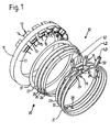
- FIG. 1 to 3 show a first exemplary embodiment of a stator 10, that as a stator for an electrical machine, especially a permanently excited one Synchronous machine designed as a starter generator for a vehicle is.
- the stator 10 has a stator yoke 11 on which a number of stator coils 12 are arranged.
- the stator coils 12 have a winding head 13 and a Insulator 14 on.
- the ends of the stator coil windings are each formed by stator coil ends 15.
- the stator coils 12 are over the circumference of the stator yoke 11 arranged on this and thereby form a through Stator coils 12 limited space 16.
- This space 16 has a diameter on by the distances between the stator coils 12 and the diameter of the stator yoke 11 is formed.
- the height of the room 16 results from the winding heads 13 of the stator coils 12, that is, through those areas of the winding heads 13, which protrude beyond the stator yoke 11.
- An interconnection arrangement 20 is located on an end face 17 of the stator yoke 11 intended.
- the interconnection arrangement 20 has three as closed Ring structure 31 formed connecting conductors 21, 22, 23.
- the connecting ladder 21, 22, 23 are made of a strip material, for example copper or the like, manufactured and each have a different diameter on.
- the connecting conductors 21, 22, 23 are formed concentrically with one another and thus are arranged radially one above the other.
- insulating layers 24, 25, 26, 27 are provided, which consist of insulating paper in the present embodiment. Over the insulation layers there is an electrical contact between the individual connecting conductors 21, 22, 23 prevented.
- the individual connecting conductors 21, 22, 23 are Via an insulating layer 37 designed as an insulating disk on the end face 17 of the Statorjochs 11 attached.
- connection extensions 28 are provided on these.
- the Number of connection extensions 28 required results from the number of am Stator yoke 11 arranged stator coils 12.
- Each stator coil end 15 is in a suitable manner, for example by means of a soldered or welded connection, attached to one of the connection extensions 28.
- connection extensions 28 protrude from it initially at an angle, preferably at a right angle, from the respective Connection conductors 21, 22, 23 from.
- recesses 29 are provided, into which the connection extensions 28 after the circuit with the stator coil ends 15 can be bent.
- the end regions 32 of the connecting conductors designed as closed ring structures 31 21, 22, 23 are as connections L1, L2, L3 for connection to a not shown electrical machine trained. To do this are the end areas 32 bent up in a corresponding manner.
- Corresponding recesses 30 are also provided for connecting conductors 21, 22, 23. Through this recess 30 of each connecting conductor Connections of adjacent connecting conductors passed without it electrical contact can occur.
- connection conductors 21, 22, 23 are bent such that the end regions 32 in their Function as connections L12, L2 L3 for connection to the electrical machine by gaps between two adjacent stator coils 12 radially can be led outside.
- the stator 10 designed according to the invention is thus particularly space-saving realizable.
- stator coils 12 are manufactured using a suitable manufacturing process, for example with the help of single tooth winding technology, automatically wrapped on single teeth.
- the stator coils 12 thus wound are then applied to the stator yoke 11.
- the individual connecting conductors 21, 22, 23 can first be made with the aid of a suitable one Process are produced as a strip material. Then be the individual recesses 29, 30 and the connection extensions 28 are formed. The tapes are cut to the desired length and then bent into closed ring structures 31. After that, their End regions 32 are bent so that they connect the connections L1, L2, L3 form with the electrical machine.
- the connecting conductors 21, 22, formed as closed ring structures 31, 23 are pushed together due to their different diameters, that they are concentric and one above the other in the radial direction are arranged. Between the individual connecting conductors 21, 22, 23 corresponding insulating layers 24, 25, 26, 27 introduced. That way Formed arrangement is pushed under the winding heads 13 of the stator coils 12.
- the configuration of the circuit arrangement according to the invention 20 achieved that the individual connecting conductors 21, 22, 23 neither in more axially in the radial direction via the winding heads 13 of the stator coils 12 protrude.
- the connections L1, L2, L3 are due to the gaps between two neighboring stator coils 12 guided radially outwards.
- connection extensions 28 which can be done using a soldering or welding process, for example. After that the connection extensions 28 are bent into the recesses 29, so that after connecting the coil ends 15 no more axial space is required becomes.
- stator 10 thus finished can be used in a subsequent process step be impregnated, which creates a solid structure.
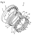
- FIGS. 4 to 6 show a further embodiment of the invention Stator 10 shown.
- such components that are structurally identical to corresponding Components of the embodiment according to FIGS. 1 to 3 are identified with identical reference numbers.
- the stator 10 shown in FIGS. 4 to 6 essentially has one same structure as the stator 10 described with reference to FIGS. 1 to 3 on so that to avoid repetition on a detailed description of the stator yoke 11 and the coils 12 is dispensed with.
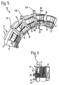
- the in 4 to 6 circuit arrangement 20 connecting conductors 21, 22, 23, which are designed in the form of an open ring structure 33.
- the individual connecting conductors 21, 22, 23 in turn have a number of connection extensions 28 and recesses 29 through which the stator coil ends 15 with the connecting conductors 21, 22, 23 already detailed in the above described way can be connected.
- the formation of the individual connecting conductors 21, 22, 23 as open ring structures 33 has the advantage that on the molding of special recesses for Passing through the connections L1, L2, L3 can be omitted.
- the single ones Connecting conductors 21, 22, 23 in turn each have a different one Diameter on.
- the connecting conductors 21, 22, 23 also have a different length. If the connecting conductors 21, 22, 23 now bent into rings, arise from the different lengths of the Individual connecting conductor clearances that take over the function of recesses and through the connections of the respective adjacent connecting conductors can be passed through.
- the coil ends 15 do not have to always connected in the shortest possible way with corresponding connection extensions 28 become.
- the length is also in such an embodiment the coil ends 15 to be connected are still so small that a clear Interconnection of the coils 12 is guaranteed.
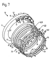
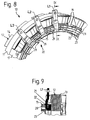
- FIGS. 7 to 9 show yet another embodiment of the invention Stator 10 shown. Identical components are again designated with identical reference numbers.
- the stator 10 according to FIGS. 7 to 9 has an interconnection arrangement 20 on, the connecting conductors 21, 22, 23 formed as closed rings 35 are.
- the closed rings 35 each have cutouts 36 in which the respective connections L1, L2, L3 for connection to an electrical machine are arranged.
- the individual recesses 36 are designed such that the connections L1, L2, L3 by adjacent connecting conductors 21, 22, 23 can be passed without causing an electrical Contact comes.
- circuit arrangement 20 results depending on the need and application.
- the invention is not limited to the examples described, so that other configurations of the circuit arrangement 20 and of the stator 10 are possible.
Landscapes
- Engineering & Computer Science (AREA)
- Power Engineering (AREA)
- Windings For Motors And Generators (AREA)
- Manufacture Of Motors, Generators (AREA)
- Insulation, Fastening Of Motor, Generator Windings (AREA)
- Iron Core Of Rotating Electric Machines (AREA)
Applications Claiming Priority (2)
| Application Number | Priority Date | Filing Date | Title |
|---|---|---|---|
| DE19920127 | 1999-05-03 | ||
| DE19920127A DE19920127C2 (de) | 1999-05-03 | 1999-05-03 | Stator für eine elektrische Maschine und Verfahren zur Herstellung eines Stators |
Publications (3)
| Publication Number | Publication Date |
|---|---|
| EP1050948A2 true EP1050948A2 (fr) | 2000-11-08 |
| EP1050948A3 EP1050948A3 (fr) | 2003-09-03 |
| EP1050948B1 EP1050948B1 (fr) | 2004-09-08 |
Family
ID=7906696
Family Applications (1)
| Application Number | Title | Priority Date | Filing Date |
|---|---|---|---|
| EP00108613A Expired - Lifetime EP1050948B1 (fr) | 1999-05-03 | 2000-04-20 | Stator pour machine électrique et procédé de fabrication d'un tel stator |
Country Status (5)
| Country | Link |
|---|---|
| US (1) | US6369473B1 (fr) |
| EP (1) | EP1050948B1 (fr) |
| JP (1) | JP3382916B2 (fr) |
| AT (1) | ATE275768T1 (fr) |
| DE (2) | DE19920127C2 (fr) |
Cited By (16)
| Publication number | Priority date | Publication date | Assignee | Title |
|---|---|---|---|---|
| FR2823612A1 (fr) * | 2001-04-17 | 2002-10-18 | Leroy Somer Moteurs | Stator de machine tournante electrique comportant des bobines individuelles demontables |
| WO2003021745A1 (fr) * | 2001-09-03 | 2003-03-13 | Honda Giken Kogyo Kabushiki Kaisha | Bague collectrice et de repartition pour stator de machine electrique rotative |
| FR2831346A1 (fr) * | 2001-10-22 | 2003-04-25 | Zf Sachs Ag | Stator pour un groupe electrique |
| US6661137B2 (en) | 2001-02-20 | 2003-12-09 | Moteurs Leroy-Somer | Drive element such as a driving wheel or a hoisting winch, the element comprising a synchronous motor |
| US6683397B2 (en) | 2001-04-17 | 2004-01-27 | Moteurs Leroy-Somer | Electric machine having at least one magnetic field detector |
| EP1184957A3 (fr) * | 2000-08-31 | 2004-09-08 | Mitsubishi Denki Kabushiki Kaisha | Moteur électrique |
| US6891299B2 (en) | 2000-05-03 | 2005-05-10 | Moteurs Leroy-Somer | Rotary electric machine having a flux-concentrating rotor and a stator with windings on teeth |
| US6975057B2 (en) | 2001-04-17 | 2005-12-13 | Moteurs Leroy-Somer | Rotary electric machine having a stator made up of sectors assembled together |
| EP1542339A4 (fr) * | 2002-07-22 | 2008-07-02 | Nsk Ltd | Moteur, procede de fabrication du moteur et dispositif de commande d'entrainement du moteur |
| EP2139094A1 (fr) * | 2008-06-26 | 2009-12-30 | ZF Friedrichshafen AG | Stator et arrangement de connection d'une machine électrique |
| US8492947B2 (en) | 2007-05-29 | 2013-07-23 | Toyota Jidosha Kabushiki Kaisha | Terminal module for rotating electric machine having a guide portion, rotating electric machine, and manufacturing method thereof |
| WO2013045986A3 (fr) * | 2011-09-26 | 2014-04-24 | Toyota Jidosha Kabushiki Kaisha | Stator pour machine électrique tournante |
| EP2400637A3 (fr) * | 2010-06-23 | 2015-06-24 | C. & E. Fein GmbH | Moteur électrique |
| WO2016184720A1 (fr) * | 2015-05-18 | 2016-11-24 | Robert Bosch Gmbh | Stator d'une machine electrique et procédé de production d'un tel stator |
| EP3491717A1 (fr) * | 2016-07-29 | 2019-06-05 | Valeo Equipements Electriques Moteur | Machine électrique tournante munie d'un interconnecteur à traces de couplage empilées radialement |
| WO2023001344A1 (fr) * | 2021-07-21 | 2023-01-26 | Bühler Motor GmbH | Stator d'une unité d'entraînement électrique et procédé de fabrication dudit stator |
Families Citing this family (60)
| Publication number | Priority date | Publication date | Assignee | Title |
|---|---|---|---|---|
| JP3489484B2 (ja) | 1999-05-19 | 2004-01-19 | 日立電線株式会社 | 射出成形端子台 |
| DE10046729A1 (de) * | 2000-09-21 | 2002-05-08 | Zf Sachs Ag | Elektrische Maschine sowie Elektrisches System |
| JP2002186212A (ja) | 2000-12-11 | 2002-06-28 | Tamagawa Seiki Co Ltd | プリント基板を有するステータ構造 |
| GB0109179D0 (en) * | 2001-04-12 | 2001-05-30 | Alstom | Improvements relating to rotary electrical machines |
| US20020171305A1 (en) * | 2001-04-17 | 2002-11-21 | Moteurs Leroy-Somer | Electric machine having an outer rotor |
| JP3733316B2 (ja) * | 2001-10-26 | 2006-01-11 | 住友電装株式会社 | 車両用薄型ブラシレスモータの集中配電部材 |
| JP3733312B2 (ja) * | 2001-10-26 | 2006-01-11 | 住友電装株式会社 | 車両用薄型ブラシレスモータの集中配電部材に用いるバスバーの製造方法 |
| JP2003134753A (ja) * | 2001-10-26 | 2003-05-09 | Sumitomo Wiring Syst Ltd | 車両用薄型ブラシレスモータの集中配電部材の製造方法 |
| JP3733313B2 (ja) * | 2001-10-26 | 2006-01-11 | 住友電装株式会社 | 車両用薄型ブラシレスモータの集中配電部材 |
| DE10212425A1 (de) * | 2002-03-21 | 2003-10-02 | Bosch Gmbh Robert | Stator für eine elektrische Maschine |
| JP3613262B2 (ja) * | 2002-04-26 | 2005-01-26 | 三菱電機株式会社 | 回転電機およびその製造方法 |
| US20040061390A1 (en) * | 2002-10-01 | 2004-04-01 | Baker-Bachman Shawn Lawrence | Apparatus and method for connecting parallel stator windings |
| DE10257579B4 (de) * | 2002-12-09 | 2008-06-12 | Dorma Gmbh + Co. Kg | Linearantrieb, insbesondere für eine Schiebetür oder dergleichen |
| FR2837993A1 (fr) * | 2003-02-14 | 2003-10-03 | Leroy Somer Moteurs | Stator pour machine electrique tournante. |
| DE10318816B4 (de) * | 2003-04-17 | 2007-06-28 | Minebea Co., Ltd. | Stator mit Verschaltungsstruktur für Statorwicklungen |
| DE102004027380B4 (de) | 2004-06-04 | 2026-02-26 | Siemens Aktiengesellschaft | Elektrische Maschine mit einem Schaltungsträger |
| KR101096469B1 (ko) * | 2003-07-10 | 2011-12-20 | 마그네틱 애플리케이션 인크. | 소형 고전력 교류 발전기 |
| DE502004011173D1 (de) * | 2003-08-02 | 2010-07-01 | Ebm Papst St Georgen Gmbh & Co | Elektromotor |
| US7116023B2 (en) * | 2004-03-23 | 2006-10-03 | Emerson Electric Co. | End cap for interconnecting winding coils of a segmented stator to reduce phase-on-phase conditions and associated methods |
| US7414347B2 (en) | 2004-03-23 | 2008-08-19 | Emerson Electric Co. | End cap for segmented stator |
| WO2006000259A1 (fr) * | 2004-06-23 | 2006-01-05 | Heinz Leiber | Machine a champ tournant a excitation par aimants permanents, pourvue d'un stator interieur et exterieur ainsi que d'un rotor tambour |
| JP4483480B2 (ja) * | 2004-08-27 | 2010-06-16 | アイシン精機株式会社 | 固定子及びモータ |
| US7327123B2 (en) * | 2005-02-02 | 2008-02-05 | Magnetic Applications, Inc. | Controller for AC generator |
| ATE349094T1 (de) * | 2005-03-17 | 2007-01-15 | Zahnradfabrik Friedrichshafen | Stator für eine elektrische maschine |
| EP1705776B1 (fr) * | 2005-03-17 | 2007-01-17 | Zf Friedrichshafen Ag | Stator pour machine électrique |
| DE202005011721U1 (de) * | 2005-07-27 | 2006-12-07 | Ebm-Papst Mulfingen Gmbh & Co. Kg | Stator eines Elektromotors mit Wicklungs-Verschaltungsanordnung |
| ATE555536T1 (de) * | 2006-01-24 | 2012-05-15 | Alstom Technology Ltd | Verbindungsanordnung für die statorwicklung einer turbomaschine mit 2 oder mehr parallelen kreisen |
| US7768165B2 (en) * | 2006-02-02 | 2010-08-03 | Magnetic Applications, Inc. | Controller for AC generator |
| JP4353950B2 (ja) * | 2006-03-06 | 2009-10-28 | 三菱電機株式会社 | 回転電機 |
| JP5176283B2 (ja) * | 2006-03-30 | 2013-04-03 | 日産自動車株式会社 | 回転電機のバスバー絶縁構造 |
| DE102006021898A1 (de) * | 2006-05-11 | 2007-11-22 | Zf Friedrichshafen Ag | Stator für eine elektrische Maschine |
| KR20100134585A (ko) * | 2008-02-07 | 2010-12-23 | 마그네틱 애플리케이션 인크. | 콤팩트한 고출력 알터네이터 |
| KR101026083B1 (ko) * | 2008-12-23 | 2011-03-31 | 주식회사 아모텍 | 슬림형 스테이터 및 그의 제조방법 |
| DE102009034238A1 (de) | 2009-07-22 | 2011-02-17 | Daimler Ag | Statorsegment und Stator eines Hybrid- oder Elektrofahrzeuges |
| DE102009034235A1 (de) | 2009-07-22 | 2011-02-17 | Daimler Ag | Stator eines Hybrid- oder Elektrofahrzeuges, Statorträger |
| CN102315730B (zh) * | 2010-07-09 | 2014-05-07 | 天津市松正电动汽车技术股份有限公司 | 电机定子绕组联接工艺 |
| CN103119834B (zh) * | 2011-09-22 | 2014-07-23 | 丰田自动车株式会社 | 旋转电机的定子 |
| JP5452570B2 (ja) * | 2011-11-09 | 2014-03-26 | 三菱電機株式会社 | 回転電機およびそのステータコイルの結線ユニットの製造方法 |
| US8907540B2 (en) | 2011-11-18 | 2014-12-09 | Remy Technologies, L.L.C. | Electric machine with insulator spacer |
| US8749107B2 (en) | 2011-12-07 | 2014-06-10 | Remy Technologies, L.L.C. | Spacer for supporting conductors in an electric machine |
| DE102011088658A1 (de) | 2011-12-15 | 2013-06-20 | Zf Friedrichshafen Ag | Stator einer elektrischen Maschine mit Spannungsisoliermitteln |
| KR101992687B1 (ko) | 2012-06-28 | 2019-06-25 | 엘지이노텍 주식회사 | 모터 |
| DE102012223371A1 (de) * | 2012-12-17 | 2014-06-18 | Zf Friedrichshafen Ag | Stator für eine elektrische Maschine |
| JP6073702B2 (ja) * | 2013-02-22 | 2017-02-01 | 住友電装株式会社 | モータの集中配電部材 |
| DE102013214386A1 (de) * | 2013-07-23 | 2015-01-29 | Zf Friedrichshafen Ag | Elektrische Maschine |
| JP6086243B2 (ja) * | 2013-10-21 | 2017-03-01 | 住友電装株式会社 | モータの集中配電部材 |
| FR3018964B1 (fr) * | 2014-03-24 | 2016-03-04 | Valeo Equip Electr Moteur | Element d'interconnexion pour le branchement des bobines du stator |
| CN105099036A (zh) * | 2014-05-12 | 2015-11-25 | 舍弗勒技术股份两合公司 | 电机及其制造方法、车用驱动装置 |
| US9742236B2 (en) * | 2014-07-29 | 2017-08-22 | Hyundai Mobis Co., Ltd. | Terminal for vehicle traction motor and method of manufacturing the same |
| US9871422B2 (en) * | 2014-09-04 | 2018-01-16 | Hyundai Mobis Co., Ltd. | Terminal unit of vehicle traction motor and method of manufacturing the same |
| JP6382080B2 (ja) * | 2014-11-25 | 2018-08-29 | 日立オートモティブシステムズ株式会社 | 回転電機の固定子、及びこれを備えた回転電機 |
| DE102016200115A1 (de) | 2016-01-08 | 2017-07-13 | Zf Friedrichshafen Ag | Stator einer elektrischen Maschine mit einer Verschaltungseinrichtung für Statorspulen und elektrische Maschine mit einem derartigen Stator |
| JP6756546B2 (ja) * | 2016-08-30 | 2020-09-16 | 日産自動車株式会社 | バスバーユニット |
| TWI636640B (zh) * | 2017-12-26 | 2018-09-21 | 群光電能科技股份有限公司 | 馬達定子結線固定裝置 |
| CN108063512B (zh) * | 2018-01-08 | 2024-02-13 | 深圳市凯中精密技术股份有限公司 | 用于电机定子的金属焊接式连接器及生产方法 |
| DE102018101231A1 (de) * | 2018-01-19 | 2019-07-25 | Brusa Elektronik Ag | Stator für eine elektrische Maschine und Verfahren zu dessen Herstellung |
| CN108808929B (zh) * | 2018-08-30 | 2024-06-21 | 珠海格力电器股份有限公司 | 用于电机定子的绝缘骨架、定子、电机和家用电器 |
| DE102018218668A1 (de) * | 2018-10-31 | 2020-04-30 | Supart GmbH | Elektromotor |
| CN112751437A (zh) * | 2019-10-30 | 2021-05-04 | 泓创绿能股份有限公司 | 一种马达定子配线结构 |
| CN112688497A (zh) * | 2020-12-18 | 2021-04-20 | 江苏中车电机有限公司 | 一种电机端环与固定座接触处绝缘修复方法 |
Family Cites Families (13)
| Publication number | Priority date | Publication date | Assignee | Title |
|---|---|---|---|---|
| JPS493101A (fr) * | 1972-04-28 | 1974-01-11 | ||
| DE2441175A1 (de) * | 1974-08-28 | 1976-03-11 | Bosch Gmbh Robert | Einrichtung zum festhalten von wicklungen auf polkernen |
| US4315179A (en) * | 1980-04-10 | 1982-02-09 | Westinghouse Electric Corp. | Double layered stator peripheral end windings |
| US4309634A (en) * | 1980-04-10 | 1982-01-05 | Westinghouse Electric Corp. | Stator winding peripheral connector rings |
| US4321497A (en) * | 1980-04-10 | 1982-03-23 | Westinghouse Electric Corp. | Peripheral connector ring stator end winding for dynamoelectric machines |
| US4689023A (en) * | 1985-08-27 | 1987-08-25 | The Superior Electric Company | Programmable electrical connector |
| US4953464A (en) * | 1987-07-13 | 1990-09-04 | Atlas Powder Company | Multi-directional signal transmission in a blast initiation system |
| US5825109A (en) * | 1994-11-30 | 1998-10-20 | Calumet Armature & Electric Co. | Vehicular oil cooled alternator with stator coil terminal assembly terminal assembly kit and method |
| US5508571A (en) * | 1994-12-12 | 1996-04-16 | General Motors Corporation | Neutral connection for wire wound stator |
| JPH0982431A (ja) * | 1995-09-19 | 1997-03-28 | Whitaker Corp:The | 電気コネクタ及びその製造方法 |
| DE19544830A1 (de) * | 1995-12-01 | 1997-06-05 | Mulfingen Elektrobau Ebm | Stator für Elektromotoren |
| DE19647559A1 (de) * | 1996-11-18 | 1997-11-27 | Mannesmann Sachs Ag | Ständer einer elektrischen Maschine |
| DE19812019A1 (de) * | 1998-03-19 | 1999-09-23 | Temic Auto Electr Motors Gmbh | Schaltungsanordnung zum Verschalten von Statorwicklungen eines bürstenlosen, elektronisch kommutierten Motors |
-
1999
- 1999-05-03 DE DE19920127A patent/DE19920127C2/de not_active Expired - Fee Related
-
2000
- 2000-04-20 AT AT00108613T patent/ATE275768T1/de not_active IP Right Cessation
- 2000-04-20 DE DE50007656T patent/DE50007656D1/de not_active Expired - Lifetime
- 2000-04-20 EP EP00108613A patent/EP1050948B1/fr not_active Expired - Lifetime
- 2000-05-03 US US09/563,386 patent/US6369473B1/en not_active Expired - Fee Related
- 2000-05-08 JP JP2000134780A patent/JP3382916B2/ja not_active Expired - Fee Related
Cited By (24)
| Publication number | Priority date | Publication date | Assignee | Title |
|---|---|---|---|---|
| US6891299B2 (en) | 2000-05-03 | 2005-05-10 | Moteurs Leroy-Somer | Rotary electric machine having a flux-concentrating rotor and a stator with windings on teeth |
| EP1184957A3 (fr) * | 2000-08-31 | 2004-09-08 | Mitsubishi Denki Kabushiki Kaisha | Moteur électrique |
| US6661137B2 (en) | 2001-02-20 | 2003-12-09 | Moteurs Leroy-Somer | Drive element such as a driving wheel or a hoisting winch, the element comprising a synchronous motor |
| FR2823612A1 (fr) * | 2001-04-17 | 2002-10-18 | Leroy Somer Moteurs | Stator de machine tournante electrique comportant des bobines individuelles demontables |
| EP1251623A1 (fr) * | 2001-04-17 | 2002-10-23 | Moteurs Leroy-Somer | Stator de machine tournante électrique comportant des bobines individuelles démontables |
| US6531797B2 (en) | 2001-04-17 | 2003-03-11 | Moteurs Leroy-Somer | Rotary electric machine stator having individual removable coils |
| US6683397B2 (en) | 2001-04-17 | 2004-01-27 | Moteurs Leroy-Somer | Electric machine having at least one magnetic field detector |
| US6975057B2 (en) | 2001-04-17 | 2005-12-13 | Moteurs Leroy-Somer | Rotary electric machine having a stator made up of sectors assembled together |
| WO2003021745A1 (fr) * | 2001-09-03 | 2003-03-13 | Honda Giken Kogyo Kabushiki Kaisha | Bague collectrice et de repartition pour stator de machine electrique rotative |
| US7193345B2 (en) | 2001-09-03 | 2007-03-20 | Honda Motor Co., Ltd. | Collecting and distributing ring for rotary electric machine stator |
| CN100386948C (zh) * | 2001-09-03 | 2008-05-07 | 本田技研工业株式会社 | 旋转电机的定子用的集配电环 |
| FR2831346A1 (fr) * | 2001-10-22 | 2003-04-25 | Zf Sachs Ag | Stator pour un groupe electrique |
| EP1542339A4 (fr) * | 2002-07-22 | 2008-07-02 | Nsk Ltd | Moteur, procede de fabrication du moteur et dispositif de commande d'entrainement du moteur |
| US8492947B2 (en) | 2007-05-29 | 2013-07-23 | Toyota Jidosha Kabushiki Kaisha | Terminal module for rotating electric machine having a guide portion, rotating electric machine, and manufacturing method thereof |
| DE112008001219B4 (de) * | 2007-05-29 | 2017-06-01 | Toyota Jidosha Kabushiki Kaisha | Verfahren zur Montage eines Anschlussmoduls für eine drehende elektrische Maschine und drehende elektrische Maschine mit diesem Modul |
| EP2139094A1 (fr) * | 2008-06-26 | 2009-12-30 | ZF Friedrichshafen AG | Stator et arrangement de connection d'une machine électrique |
| EP2400637A3 (fr) * | 2010-06-23 | 2015-06-24 | C. & E. Fein GmbH | Moteur électrique |
| US9225216B2 (en) | 2010-06-23 | 2015-12-29 | C. & E. Fein Gmbh | Electric motor and method of producing an electric motor that is commutated electronically |
| WO2013045986A3 (fr) * | 2011-09-26 | 2014-04-24 | Toyota Jidosha Kabushiki Kaisha | Stator pour machine électrique tournante |
| US10424983B2 (en) | 2011-09-26 | 2019-09-24 | Toyota Jidosha Kabushiki Kaisha | Stator for rotary electric machine |
| WO2016184720A1 (fr) * | 2015-05-18 | 2016-11-24 | Robert Bosch Gmbh | Stator d'une machine electrique et procédé de production d'un tel stator |
| EP3491717A1 (fr) * | 2016-07-29 | 2019-06-05 | Valeo Equipements Electriques Moteur | Machine électrique tournante munie d'un interconnecteur à traces de couplage empilées radialement |
| EP3491717B1 (fr) * | 2016-07-29 | 2025-08-20 | Valeo Electrification | Machine électrique tournante munie d'un interconnecteur à traces de couplage empilées radialement |
| WO2023001344A1 (fr) * | 2021-07-21 | 2023-01-26 | Bühler Motor GmbH | Stator d'une unité d'entraînement électrique et procédé de fabrication dudit stator |
Also Published As
| Publication number | Publication date |
|---|---|
| EP1050948A3 (fr) | 2003-09-03 |
| DE50007656D1 (de) | 2004-10-14 |
| DE19920127A1 (de) | 2000-11-16 |
| JP3382916B2 (ja) | 2003-03-04 |
| DE19920127C2 (de) | 2001-05-31 |
| ATE275768T1 (de) | 2004-09-15 |
| EP1050948B1 (fr) | 2004-09-08 |
| JP2000333418A (ja) | 2000-11-30 |
| US6369473B1 (en) | 2002-04-09 |
Similar Documents
| Publication | Publication Date | Title |
|---|---|---|
| EP1050948B1 (fr) | Stator pour machine électrique et procédé de fabrication d'un tel stator | |
| DE60311045T2 (de) | Segmentierter Anker und AC-Maschine, die selbigen benutzt | |
| DE69833155T2 (de) | Spulenverbindungsvorrichtung für einen Ausseläufermultipolegenerator | |
| DE2211184C3 (de) | Scheibenanker | |
| DE102012219668A1 (de) | Verfahren zum Binden von Statorspulen eines Motors | |
| DE102005001705A1 (de) | Verfahren zur Herstellung von Ankern, Verfahren zur Herstellung von Elektromotoren sowie Anker | |
| DE102004004083A1 (de) | Einlochwicklung-Statorwicklungseinheit für eine elektrische Rotationsmaschine | |
| CH695810A5 (de) | Statorkernanordnung. | |
| DE10103935A1 (de) | Statoranordnung einer elektrischen Umlaufmaschine für ein Fahrzeug | |
| DE102015225585A1 (de) | Wicklung für eine elektrische Maschine und Verfahren zu deren Herstellung | |
| DE102004003557A1 (de) | Stator für eine dynamoelektrische Maschine | |
| DE10056555A1 (de) | Stator für dynamo-elektrische Maschinen | |
| EP3641105A1 (fr) | Moteur à courant continu et son procédé de fabrication | |
| EP1127399A1 (fr) | Dispositif pour convertir de l'energie electrique en energie mecanique et/ou inversement et procede pour produire un dispositif de ce type | |
| DE102011120985A1 (de) | Elektrische Maschine mit einem Stator und Wickel- und Kontaktierungsverfahren für eine elektrische Maschine | |
| DE102019210146A1 (de) | Stator eines elektromotors und verfahren zu seiner herstellung | |
| DE102005024653A1 (de) | Stator einer sich drehenden elektrischen Maschine und Herstellungsverfahren des Stators | |
| EP3216113A1 (fr) | Rotor ou stator à tête de bobine plate obtenue par insertion | |
| DE10038234A1 (de) | Verfahren und Satz zur Herstellung eines Ständers einer Elektrischen Maschine sowie Ständer für eine Elektrische Maschine | |
| DE102018125834A1 (de) | Stator für eine elektrische Maschine und Verfahren zum Herstellen eines derartigen Stators | |
| DE4244694C2 (de) | Verfahren zur Herstellung einer mehrphasigen elektrischen Maschine | |
| DE102014225125A1 (de) | Anker und Motor | |
| DE102004057750B4 (de) | Verfahren zur Herstellung eines Kommutators sowie Kommutator | |
| EP1278288A2 (fr) | Moteur à rotor extérieur | |
| DE102021127073A1 (de) | Rotor mit Querverbindern, elektrische Maschine sowie Verfahren zum Herstellen eines Rotors |
Legal Events
| Date | Code | Title | Description |
|---|---|---|---|
| PUAI | Public reference made under article 153(3) epc to a published international application that has entered the european phase |
Free format text: ORIGINAL CODE: 0009012 |
|
| AK | Designated contracting states |
Kind code of ref document: A2 Designated state(s): AT BE CH CY DE DK ES FI FR GB GR IE IT LI LU MC NL PT SE |
|
| AX | Request for extension of the european patent |
Free format text: AL;LT;LV;MK;RO;SI |
|
| RAP1 | Party data changed (applicant data changed or rights of an application transferred) |
Owner name: ZF SACHS AG |
|
| PUAL | Search report despatched |
Free format text: ORIGINAL CODE: 0009013 |
|
| AK | Designated contracting states |
Kind code of ref document: A3 Designated state(s): AT BE CH CY DE DK ES FI FR GB GR IE IT LI LU MC NL PT SE |
|
| AX | Request for extension of the european patent |
Extension state: AL LT LV MK RO SI |
|
| 17P | Request for examination filed |
Effective date: 20031018 |
|
| GRAP | Despatch of communication of intention to grant a patent |
Free format text: ORIGINAL CODE: EPIDOSNIGR1 |
|
| AKX | Designation fees paid |
Designated state(s): AT BE CH CY DE DK ES FI FR GB GR IE IT LI LU MC NL PT SE |
|
| GRAS | Grant fee paid |
Free format text: ORIGINAL CODE: EPIDOSNIGR3 |
|
| GRAA | (expected) grant |
Free format text: ORIGINAL CODE: 0009210 |
|
| AK | Designated contracting states |
Kind code of ref document: B1 Designated state(s): AT BE CH CY DE DK ES FI FR GB GR IE IT LI LU MC NL PT SE |
|
| PG25 | Lapsed in a contracting state [announced via postgrant information from national office to epo] |
Ref country code: IT Free format text: LAPSE BECAUSE OF FAILURE TO SUBMIT A TRANSLATION OF THE DESCRIPTION OR TO PAY THE FEE WITHIN THE PRESCRIBED TIME-LIMIT;WARNING: LAPSES OF ITALIAN PATENTS WITH EFFECTIVE DATE BEFORE 2007 MAY HAVE OCCURRED AT ANY TIME BEFORE 2007. THE CORRECT EFFECTIVE DATE MAY BE DIFFERENT FROM THE ONE RECORDED. Effective date: 20040908 Ref country code: NL Free format text: LAPSE BECAUSE OF FAILURE TO SUBMIT A TRANSLATION OF THE DESCRIPTION OR TO PAY THE FEE WITHIN THE PRESCRIBED TIME-LIMIT Effective date: 20040908 Ref country code: FI Free format text: LAPSE BECAUSE OF FAILURE TO SUBMIT A TRANSLATION OF THE DESCRIPTION OR TO PAY THE FEE WITHIN THE PRESCRIBED TIME-LIMIT Effective date: 20040908 Ref country code: IE Free format text: LAPSE BECAUSE OF FAILURE TO SUBMIT A TRANSLATION OF THE DESCRIPTION OR TO PAY THE FEE WITHIN THE PRESCRIBED TIME-LIMIT Effective date: 20040908 |
|
| REG | Reference to a national code |
Ref country code: GB Ref legal event code: FG4D Free format text: NOT ENGLISH |
|
| REG | Reference to a national code |
Ref country code: CH Ref legal event code: EP |
|
| REG | Reference to a national code |
Ref country code: IE Ref legal event code: FG4D Free format text: GERMAN |
|
| REF | Corresponds to: |
Ref document number: 50007656 Country of ref document: DE Date of ref document: 20041014 Kind code of ref document: P |
|
| PG25 | Lapsed in a contracting state [announced via postgrant information from national office to epo] |
Ref country code: SE Free format text: LAPSE BECAUSE OF FAILURE TO SUBMIT A TRANSLATION OF THE DESCRIPTION OR TO PAY THE FEE WITHIN THE PRESCRIBED TIME-LIMIT Effective date: 20041208 Ref country code: DK Free format text: LAPSE BECAUSE OF FAILURE TO SUBMIT A TRANSLATION OF THE DESCRIPTION OR TO PAY THE FEE WITHIN THE PRESCRIBED TIME-LIMIT Effective date: 20041208 Ref country code: GR Free format text: LAPSE BECAUSE OF FAILURE TO SUBMIT A TRANSLATION OF THE DESCRIPTION OR TO PAY THE FEE WITHIN THE PRESCRIBED TIME-LIMIT Effective date: 20041208 |
|
| PG25 | Lapsed in a contracting state [announced via postgrant information from national office to epo] |
Ref country code: ES Free format text: LAPSE BECAUSE OF FAILURE TO SUBMIT A TRANSLATION OF THE DESCRIPTION OR TO PAY THE FEE WITHIN THE PRESCRIBED TIME-LIMIT Effective date: 20041219 |
|
| GBT | Gb: translation of ep patent filed (gb section 77(6)(a)/1977) |
Effective date: 20050112 |
|
| NLV1 | Nl: lapsed or annulled due to failure to fulfill the requirements of art. 29p and 29m of the patents act | ||
| PGFP | Annual fee paid to national office [announced via postgrant information from national office to epo] |
Ref country code: GB Payment date: 20050411 Year of fee payment: 6 |
|
| PG25 | Lapsed in a contracting state [announced via postgrant information from national office to epo] |
Ref country code: LU Free format text: LAPSE BECAUSE OF NON-PAYMENT OF DUE FEES Effective date: 20050420 Ref country code: AT Free format text: LAPSE BECAUSE OF NON-PAYMENT OF DUE FEES Effective date: 20050420 Ref country code: CY Free format text: LAPSE BECAUSE OF FAILURE TO SUBMIT A TRANSLATION OF THE DESCRIPTION OR TO PAY THE FEE WITHIN THE PRESCRIBED TIME-LIMIT Effective date: 20050420 |
|
| REG | Reference to a national code |
Ref country code: IE Ref legal event code: FD4D |
|
| PG25 | Lapsed in a contracting state [announced via postgrant information from national office to epo] |
Ref country code: CH Free format text: LAPSE BECAUSE OF NON-PAYMENT OF DUE FEES Effective date: 20050430 Ref country code: BE Free format text: LAPSE BECAUSE OF NON-PAYMENT OF DUE FEES Effective date: 20050430 Ref country code: MC Free format text: LAPSE BECAUSE OF NON-PAYMENT OF DUE FEES Effective date: 20050430 Ref country code: LI Free format text: LAPSE BECAUSE OF NON-PAYMENT OF DUE FEES Effective date: 20050430 |
|
| ET | Fr: translation filed | ||
| PLBE | No opposition filed within time limit |
Free format text: ORIGINAL CODE: 0009261 |
|
| STAA | Information on the status of an ep patent application or granted ep patent |
Free format text: STATUS: NO OPPOSITION FILED WITHIN TIME LIMIT |
|
| 26N | No opposition filed |
Effective date: 20050609 |
|
| BERE | Be: lapsed |
Owner name: *ZF SACHS A.G. Effective date: 20050430 |
|
| REG | Reference to a national code |
Ref country code: CH Ref legal event code: PL |
|
| PG25 | Lapsed in a contracting state [announced via postgrant information from national office to epo] |
Ref country code: GB Free format text: LAPSE BECAUSE OF NON-PAYMENT OF DUE FEES Effective date: 20060420 |
|
| GBPC | Gb: european patent ceased through non-payment of renewal fee |
Effective date: 20060420 |
|
| BERE | Be: lapsed |
Owner name: *ZF SACHS A.G. Effective date: 20050430 |
|
| PG25 | Lapsed in a contracting state [announced via postgrant information from national office to epo] |
Ref country code: PT Free format text: LAPSE BECAUSE OF NON-PAYMENT OF DUE FEES Effective date: 20050208 |
|
| PGFP | Annual fee paid to national office [announced via postgrant information from national office to epo] |
Ref country code: FR Payment date: 20080312 Year of fee payment: 9 |
|
| REG | Reference to a national code |
Ref country code: FR Ref legal event code: ST Effective date: 20091231 |
|
| PG25 | Lapsed in a contracting state [announced via postgrant information from national office to epo] |
Ref country code: FR Free format text: LAPSE BECAUSE OF NON-PAYMENT OF DUE FEES Effective date: 20091222 |
|
| PGFP | Annual fee paid to national office [announced via postgrant information from national office to epo] |
Ref country code: DE Payment date: 20100430 Year of fee payment: 11 |
|
| REG | Reference to a national code |
Ref country code: DE Ref legal event code: R119 Ref document number: 50007656 Country of ref document: DE |
|
| REG | Reference to a national code |
Ref country code: DE Ref legal event code: R119 Ref document number: 50007656 Country of ref document: DE |
|
| PG25 | Lapsed in a contracting state [announced via postgrant information from national office to epo] |
Ref country code: DE Free format text: LAPSE BECAUSE OF NON-PAYMENT OF DUE FEES Effective date: 20111031 |