EP1051268B1 - Machine a cintrer les tubes et son dispositif a barillet - Google Patents
Machine a cintrer les tubes et son dispositif a barillet Download PDFInfo
- Publication number
- EP1051268B1 EP1051268B1 EP98958951A EP98958951A EP1051268B1 EP 1051268 B1 EP1051268 B1 EP 1051268B1 EP 98958951 A EP98958951 A EP 98958951A EP 98958951 A EP98958951 A EP 98958951A EP 1051268 B1 EP1051268 B1 EP 1051268B1
- Authority
- EP
- European Patent Office
- Prior art keywords
- bending
- jaws
- turret
- tube
- head
- Prior art date
- Legal status (The legal status is an assumption and is not a legal conclusion. Google has not performed a legal analysis and makes no representation as to the accuracy of the status listed.)
- Expired - Lifetime
Links
- 238000005452 bending Methods 0.000 title claims abstract description 129
- 230000002093 peripheral effect Effects 0.000 claims description 8
- 238000000034 method Methods 0.000 claims description 3
- 230000000295 complement effect Effects 0.000 description 4
- 238000006073 displacement reaction Methods 0.000 description 2
- 240000007817 Olea europaea Species 0.000 description 1
- 238000013459 approach Methods 0.000 description 1
- 238000009434 installation Methods 0.000 description 1
- 238000007493 shaping process Methods 0.000 description 1
Images






Classifications
-
- B—PERFORMING OPERATIONS; TRANSPORTING
- B21—MECHANICAL METAL-WORKING WITHOUT ESSENTIALLY REMOVING MATERIAL; PUNCHING METAL
- B21D—WORKING OR PROCESSING OF SHEET METAL OR METAL TUBES, RODS OR PROFILES WITHOUT ESSENTIALLY REMOVING MATERIAL; PUNCHING METAL
- B21D37/00—Tools as parts of machines covered by this subclass
- B21D37/14—Particular arrangements for handling and holding in place complete dies
-
- B—PERFORMING OPERATIONS; TRANSPORTING
- B21—MECHANICAL METAL-WORKING WITHOUT ESSENTIALLY REMOVING MATERIAL; PUNCHING METAL
- B21D—WORKING OR PROCESSING OF SHEET METAL OR METAL TUBES, RODS OR PROFILES WITHOUT ESSENTIALLY REMOVING MATERIAL; PUNCHING METAL
- B21D7/00—Bending rods, profiles, or tubes
- B21D7/02—Bending rods, profiles, or tubes over a stationary forming member; by use of a swinging forming member or abutment
- B21D7/024—Bending rods, profiles, or tubes over a stationary forming member; by use of a swinging forming member or abutment by a swinging forming member
Definitions
- the present invention relates to a machine for bending tubes according to the preamble of claim 1 (see e.g. EP-A-0 120 336) and to a barrel device according to the preamble of claim 6 for changing the clamping jaws on a bending the tubes and its implementation method.
- the carriage advances the pipe and the mandrel turn the hose to position it in relation to the tools.
- the pressure tool can apply the rear part of the pipe against the tool or against another backpressure member or a cam.
- the clamping and bending tools cooperate to clamp a front part of the pipe, and are simultaneously rotated about an axis substantially vertical. This causes the curvature of the pipe around the bending tool. Then, the tools are retracted, the carriage is advanced, and the mandrel is driven in rotation in order to place the hose properly in position at a time longitudinally and in rotation for the next bend.
- the entire bending head includes a fixed arm assembly in which is mounted the rotary drive mechanism of the bending tool. On the stationary arm is also mounted the actuation mechanism of the tool pressure.
- a tilting bending arm assembly is mounted on the assembly fixed arm so as to be integral in rotation with the bending tools around the axis of these and this set carries the clamping tools and their mechanism actuating.
- the machine is preferably controlled fully automatically in order to to execute a series of bends on a given pipe.
- the bending tool is formed by a stack of coaxial bending tools having different curvatures.
- the machine can have either of the tools or bending dies next to the pipe, because the whole bending head is mounted mobile on the front end of the machine frame. Indeed, the head of bending can move in two directions, vertical and horizontal, in two directions which are perpendicular to each other, and both perpendicular to the axis of the machine.
- the bending machine and its barrel device according to the present invention have for the purpose of bringing to the level of the bending head of the machine jaws of tightening with imprints of different shapes and power select the one corresponding to the outer profile of the tube to be bent by simple rotation of said barrel device about its longitudinal axis.
- the machine for bending tubes according to the invention comprises all the features of claim 1.
- the machine for bending tubes according to the invention advantageously comprises a barrel made up a square plate, each peripheral edge of which has a fixing device allowing the sliding of the clamping jaws correspondents.
- the machine for bending tubes according to the invention advantageously comprises a barrel whose clamping jaws have an imprint of different and complementary shape to the profile of the tube before bending.
- the tube bending machine advantageously comprises a jaw support having on a vertical edge a groove which cooperates with an element integral with either one of the jaws of the clamping jaw corresponding, either of said jaw support.
- the machine for bending tubes according to the invention advantageously comprises a bending head which moves in a horizontal direction lying in a plane perpendicular to that containing the longitudinal axis of the fixed frame.
- the barrel device according to the invention comprises all the features of claim 6.
- the barrel device according to the invention advantageously comprises a barrel which is constituted a square plate, each peripheral edge of which has a fixing device allowing the sliding of the clamping jaws correspondents.
- the barrel device according to the invention advantageously comprises clamping jaws with imprints of different shapes and complementary to the profile of the tube before bending.
- the barrel device advantageously comprises a jaw support comprising on a vertical edge a groove which cooperates with an intermediate element integral either with one of the jaws of the corresponding clamping jaw, or with said jaw support.
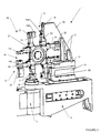
- FIG. 1 shows a bending machine 1 comprising a fixed frame 2 which carries at one of its ends a bending head 3 around which pivots a bending arm 4.
- the fixed frame 2 comprises along its longitudinal axis a guide rail 5 on which slides a carriage 6 which approaches and moves away from the bending head 3.
- the carriage 6 comprises a mandrel 7 for receiving and guiding a tube 8 to bend which is moved in translation and in rotation around its axis.
- a device 9 also slides on the rail 5 to avoid, by means of an olive, the crushing of the tube 8 during its bending.
- the bending arm 4 comprises a jaw support 10 which moves horizontally in the direction of the bending head 3.
- the support 10 is integral a vertical plate 11 extending above said support.
- the vertical plate is designed to carry a barrel device 12.
- the bending head 3 is integral with a bending roller 13 constituting a device for fixing one of the jaws of a clamping jaw 14 as shown will see better later.
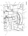
- the bending roller 13 has a circular profile, one of which part is cut to form a notch 28 in L.
- the roller 13 comprises a peripheral groove 30 whose bending radius can vary depending on the shaping to be carried out on the tube 8.
- the bending head 3 includes displacement means, in order to be able to move horizontally relative to the fixed frame 2, i.e. in one direction lying in a plane perpendicular to that containing the longitudinal axis of the machine 1 or of the fixed frame 2, which is generally embodied by the tube 8.
- the jaw support 10 has on its vertical edge 15, located opposite the bending head 3, a T-shaped groove 16.
- the groove 16 can be provided according to another profile in order to constitute a vertical slide opening on the side the upper and horizontal edge of the jaw support 10.
- the vertical plate 11 is integral with beams 17 extending vertically and over which is welded a barrel holder 18.
- the latter is integral with a rib vertical 19 arranged in a plane parallel to that containing the groove 16 of the jaw support 10 to allow vertical movement of a barrel 20.
- the barrel 20 consists of a plate 21 with a square profile, each edge of which peripheral includes a fixing device 22 for the installation of a jaw clamp 14.
- Each fixing device 22 of the barrel 20 comprises at each angle of the plate 21 a jaw 23 and 24 of a clamping jaw 14.
- each clamping jaw 14 comprise respectively an imprint 14a, 14b of shape complementary to the profile outside of tube 8 before bending.
- the imprints 14a, 14b have a additional profile which can be either bent, or of different length, or orientation in different space to constitute clamping jaws 14 to different imprints on each peripheral edge of the barrel 20.
- the jaws 23 and 24 of each clamping jaw 14 are provided to be move along the peripheral edge of the plate 21 towards the tube 8 held on the fixed frame 2 of the machine 1.
- Each jaw 24 has on the face opposite to that receiving the imprint 14b of the clamping jaw 14, a rib 25 which is designed to cooperate with a intermediate element 29 which is housed in the groove 16 of the jaw support 10 of the bending arm 4 during the vertical movements of the barrel 20.
- the intermediate element 29 can be positioned beforehand either on the jaw 24, or on the jaw support 10, to allow indexing of said jaw on said jaw support.
- each clamping jaw 14 has, opposite its footprint 14 has a profile 31 complementary to the notch 28 for its attachment to the bending roller 13.
- the barrel 20 can move vertically along the barrel holder 18 and in a plane parallel to that containing said barrel holder by means of a motor 26 or any other electrical or hydraulic means.
- the vertical displacement of the barrel 20 makes it possible to introduce and / or remove the jaws 23 and 24 of the clamping jaw 14 corresponding to the bending roller 13 of the bending head 3 and of the jaw support 10 of the bending arm 4.
- the barrel 20 can be rotated about its axis longitudinal by means of another motor 27 to arrange, above the roller bending 13 of the bending head 3 and of the jaw support 10 of the bending arm 4, the clamping jaw 14 corresponding to the external profile of the tube 8 before it bending.
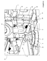
- the barrel device 12 is placed in the high position by the motor 26, so that the barrel 20 is disposed above the bending head 3 and the arm of bending 4 (figure 5).
- the barrel 20 is then rotated about its longitudinal axis by through the motor 27, to determine the clamping jaw 14 as a function of the imprint 14a, 14b corresponding to the external profile of the tube 8 ( Figure 5).
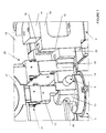
- the barrel device 12 is placed in the low position by the motor 26, so that the jaws 23 and 24 of the corresponding clamping jaw 14 are arranged at the same level as the tube 8 ( Figure 6).
- the descent of the barrel 20 makes it possible to simultaneously index the jaw 23 on the bending roller 13 of the bending head 3 and the jaw 24 on the support jaw 10 of the bending arm 4.
- the profile 31 of the jaw 23 is positioned in the notch 28 in L, while the intermediate element 29 of the jaw 24 cooperates with the groove 16 of the jaw support 10 ( Figure 6).
- the bending arm 4 then pivots around the vertical axis of the bending head 3 to return to its original position shown in FIG. 5, in order to be able to select a new clamping jaw 14 and repeat a cycle again bending as previously described.
- the barrel device 12 can move on the one hand in rotation around its longitudinal axis and on the other hand in directions included in planes perpendicular and / or parallel to that containing the axis longitudinal of the fixed frame 2 which is represented by the axis of the tube to be bent 8.
Landscapes
- Engineering & Computer Science (AREA)
- Mechanical Engineering (AREA)
- Bending Of Plates, Rods, And Pipes (AREA)
Abstract
Description
- à positionner le dispositif à barillet en position haute sur le porte-barillet par l'intermédiaire du moteur ;
- à faire pivoter le barillet autour de son axe longitudinal au moyen d'un autre moteur pour choisir le mors de serrage en fonction de l'empreinte correspondant au profil du tube avant son cintrage ;
- à descendre le dispositif à barillet pour que les mâchoires du mors de serrage correspondant viennent s'indexer simultanément et respectivement sur le galet de cintrage de la tête de cintrage et le support de mors du bras de cintrage ;
- à déplacer horizontalement en direction du tube la tête de cintrage et le support de mors pour amener les mâchoires du mors de serrage contre ledit tube ;
- à cintrer le tube en pivotant le bras de cintrage et le dispositif à barillet autour de la tête de cintrage et du galet de cintrage.
Claims (10)
- Machine à cintrer les tubes comportant un bâti fixe allongé (2) solidaire à l'une de ses extrémités d'une tête de cintrage (3) et d'un bras de cintrage (4) pivotant autour de ladite tête, le bras de cintrage (4) comprenant un dispositif à barillet (12) portant des mors de serrage (14) d'empreintes différentes pouvant pivoter en même temps que ledit bras autour de la tête de cintrage (3) pour réaliser la mise en forme de tubes (8), caractérisé en ce que le dispositif à barillet (12) est constitué d'un porte-barillet (18) solidaire du support de mors (10) coulissant sur le bras de cintrage (4), d'un barillet (20) se déplaçant verticalement sur le porte-barillet (18) par l'intermédiaire d'un moteur (26) et en rotation autour de son propre axe longitudinal au moyen d'un autre moteur (27), ledit barillet (20) comportant sur sa périphérie au moins deux mors de serrage (14) comportant chacun deux mâchoires (23, 24) opposées qui coopèrent respectivement avec un galet de cintrage (13) de la tête de cintrage (3) et le support de mors (10) du bras de cintrage (4).
- Machine à cintrer suivant la revendication 1, caractérisée en ce que le barillet (20) est constitué d'une plaque (21) de forme carrée dont chaque bord périphérique comporte un dispositif de fixation (22) permettant le coulissement des mors de serrage (14) correspondants.
- Machine à cintrer suivant la revendication 1, caractérisée en ce que chaque mors de serrage (14) comporte une empreinte (14a, 14b) complémentaire au profil extérieur du tube (8) avant son cintrage.
- Machine à cintrer suivant la revendication 1, caractérisée en ce que le support de mors (10) comporte sur un bord vertical (15) une rainure (16) qui coopère avec un élément intermédiaire (29) solidaire soit d'une des mâchoires (24) du mors de serrage (14) correspondant, soit dudit support de mors.
- Machine à cintrer suivant la revendication 1, caractérisée en ce que la tête de cintrage (3) se déplace suivant une direction horizontale se trouvant dans un plan perpendiculaire à celui contenant l'axe longitudinal du bâti fixe (2).
- Dispositif à barillet pour machine à cintrer les tubes, la machine comportant un bâti fixe (2) solidaire à l'une de ses extrémités d'une tête de cintrage (3) et d'un bras de cintrage (4) pivotant autour de ladite tête, ledit dispositif à barillet (12) portant des mors de serrage (14) d'empreintes différentes et comportant des moyens de déplacement qui permettent d'une part le déplacement en rotation du dispositif à barillet (12) autour de son propre axe longitudinal et d'autre part le déplacement du dispositif à barillet suivant une direction perpendiculaire et verticale par rapport au bâti fixe (2), caractérisé en ce qu'il comprend un porte-barillet (18) solidaire d'un support de mors (10) adapté à coulisser sur le bras de cintrage (4), un barillet (20) se déplaçant d'une part en translation verticale sur le porte-barillet (18) par l'intermédiaire d'un moteur (26) et d'autre part en rotation autour de son propre axe longitudinal au moyen d'un autre moteur (27), ledit barillet (20) comportant sur sa périphérie au moins deux mors de serrage (14) comportant chacun deux mâchoires opposées (23, 24) adaptées à coopérer respectivement avec un galet de cintrage (13) de la tête de cintrage (3) et le support de mors (10) du bras de cintrage (4).
- Dispositif à barillet suivant la revendication 6, caractérisé en ce que le barillet (20) est constitué d'une plaque (21) de forme carrée dont chaque bord périphérique comporte un dispositif de fixation (22) permettant le coulissement des mors de serrage (14) correspondants.
- Dispositif à barillet suivant la revendication 6, caractérisé en ce que chaque mors de serrage (14) comporte une empreinte (14a, 14b) complémentaire au profil extérieur du tube (8) avant son cintrage.
- Dispositif à barillet suivant la revendication 6, caractérisée en ce que le support de mors (10) comporte sur un bord vertical (15) une rainure (16) qui coopère avec un élément intermédiaire (29) solidaire soit d'une des mâchoires (24) du mors de serrage (14) correspondant, soit dudit support de mors.
- Procédé de chargement d'un mors de serrage (14) pour la mise en oeuvre d'une machine à cintrer les tubes qui comportent un bâti fixe allongé (2) solidaire à l'une de ses extrémités une tête de cintrage (3) et un bras de cintrage (4) pivotant autour de ladite tête suivant une des revendications 1 à 5, caractérisé en ce qu'il consiste :à positionner le dispositif à barillet (12) en position haute sur le porte-barillet (18) par l'intermédiaire du moteur (26) ;à faire pivoter le barillet (20) autour de son axe longitudinal au moyen du moteur (27) pour choisir le mors de serrage (14) en fonction de l'empreinte correspondant au profil extérieur du tube (8) avant son cintrage ;à descendre le dispositif à barillet (20) pour que les mâchoires (23, 24) du mors de serrage (14) correspondant viennent s'indexer simultanément et respectivement sur le galet de cintrage (13) de la tête de cintrage (3) et le support de mors (10) du bras de cintrage (4) ;à déplacer horizontalement en direction du tube (8) la tête de cintrage (3) et le support de mors (10) pour amener les mâchoires (23, 24) du mors de serrage (14) correspondant contre ledit tube ;à cintrer le tube (8) en pivotant le bras de cintrage (4) et le dispositif à barillet (20) autour de la tête de cintrage (3) et du galet de cintrage (13).
Applications Claiming Priority (3)
| Application Number | Priority Date | Filing Date | Title |
|---|---|---|---|
| FR9801315 | 1998-01-30 | ||
| FR9801315A FR2774317B1 (fr) | 1998-01-30 | 1998-01-30 | Machine a cintrer les tubes et son dispositif a barillet |
| PCT/FR1998/002606 WO1999038626A1 (fr) | 1998-01-30 | 1998-12-03 | Machine a cintrer les tubes et son dispositif a barillet |
Publications (2)
| Publication Number | Publication Date |
|---|---|
| EP1051268A1 EP1051268A1 (fr) | 2000-11-15 |
| EP1051268B1 true EP1051268B1 (fr) | 2002-05-22 |
Family
ID=9522606
Family Applications (1)
| Application Number | Title | Priority Date | Filing Date |
|---|---|---|---|
| EP98958951A Expired - Lifetime EP1051268B1 (fr) | 1998-01-30 | 1998-12-03 | Machine a cintrer les tubes et son dispositif a barillet |
Country Status (6)
| Country | Link |
|---|---|
| US (1) | US6345525B1 (fr) |
| EP (1) | EP1051268B1 (fr) |
| CA (1) | CA2318385C (fr) |
| DE (1) | DE69805550T2 (fr) |
| FR (1) | FR2774317B1 (fr) |
| WO (1) | WO1999038626A1 (fr) |
Families Citing this family (12)
| Publication number | Priority date | Publication date | Assignee | Title |
|---|---|---|---|---|
| DE10130937C1 (de) * | 2001-06-27 | 2003-01-30 | Fraunhofer Ges Forschung | Verfahren und Vorrichtung zur Ermittlung der Raumgeometrie eines gebogenen Strangprofils |
| EP1380361B1 (fr) | 2002-07-13 | 2006-08-16 | Trumpf Werkzeugmaschinen GmbH + Co. KG | Dispositif de cintrage avec outil de cintrage et entraînement de cintrage |
| EP1380362B1 (fr) * | 2002-07-13 | 2008-03-26 | Trumpf Werkzeugmaschinen GmbH + Co. KG | Machine de cintrage de tubes avec alimentation de tubes et recul de mandrin |
| DE102005012551B4 (de) * | 2005-03-18 | 2008-06-12 | Tracto-Technik Gmbh | Wechselvorrichtung für ein Biegemaschinensystem sowie ein Biegemaschinensystem und ein Verfahren zum Umrüsten einer Biegemaschine |
| FR3001163B1 (fr) | 2013-01-21 | 2015-05-01 | Eaton Leonard Europ | Dispositif de cintrage de profiles tels que des tubes |
| FR3007301B1 (fr) * | 2013-06-25 | 2015-06-05 | Financ Jaubert | Machine a cintrer un profile |
| ITUA20161931A1 (it) | 2016-03-23 | 2017-09-23 | Crippa Spa | Dispositivo per la curvatura di un materiale filiforme |
| CN109483935B (zh) * | 2018-12-21 | 2023-12-05 | 东山欧凯金属塑料制品有限公司 | 物料缩径机 |
| CN109604395A (zh) * | 2019-01-30 | 2019-04-12 | 杭州显庆科技有限公司 | 一种工件折弯机构及其方法和弯管设备 |
| CN110000256B (zh) * | 2019-04-15 | 2024-04-26 | 广东捷泰克智能装备有限公司 | 多用途弯管机 |
| IT201900006821A1 (it) * | 2019-05-14 | 2020-11-14 | Star Tech S R L | Macchina per la curvatura di elementi allungati quali barre, tubi e simili e metodo di funzionamento di tale macchina |
| CN111992602B (zh) * | 2020-09-02 | 2025-05-23 | 珠海市科箭自动化设备有限公司 | 一种弯管设备 |
Family Cites Families (8)
| Publication number | Priority date | Publication date | Assignee | Title |
|---|---|---|---|---|
| DE25279C (de) * | W. NUSSBECK in Berlin, Neuer Markt 8 | Bierkühlapparat | ||
| US3431759A (en) * | 1966-02-02 | 1969-03-11 | Walker Mfg Co | Forming apparatus |
| DE2626202C2 (de) * | 1976-06-11 | 1992-10-29 | Rigobert Dipl.-Ing. 5000 Köln Schwarze | Rohrbiegemaschine |
| US4495788A (en) * | 1982-08-02 | 1985-01-29 | Eaton-Leonard Corporation | Multiple curvature bender |
| DE3471892D1 (en) | 1983-03-26 | 1988-07-14 | Schwarze Rigobert | Tube bending machine |
| GB2187666B (en) * | 1986-03-15 | 1989-12-20 | Pressbend Ltd | Pipe bending apparatus |
| DE3616302A1 (de) * | 1986-05-14 | 1987-11-19 | Schwarze Rigobert | Rohrbiegemaschine |
| DE19530805A1 (de) * | 1995-08-22 | 1997-02-27 | Schwarze Rigobert | CNC-gesteuerte Rohrbiegemaschine |
-
1998
- 1998-01-30 FR FR9801315A patent/FR2774317B1/fr not_active Expired - Fee Related
- 1998-12-03 CA CA002318385A patent/CA2318385C/fr not_active Expired - Lifetime
- 1998-12-03 EP EP98958951A patent/EP1051268B1/fr not_active Expired - Lifetime
- 1998-12-03 WO PCT/FR1998/002606 patent/WO1999038626A1/fr not_active Ceased
- 1998-12-03 DE DE69805550T patent/DE69805550T2/de not_active Expired - Lifetime
- 1998-12-03 US US09/589,596 patent/US6345525B1/en not_active Expired - Lifetime
Also Published As
| Publication number | Publication date |
|---|---|
| DE69805550D1 (de) | 2002-06-27 |
| DE69805550T2 (de) | 2003-01-09 |
| CA2318385A1 (fr) | 1999-08-05 |
| US6345525B1 (en) | 2002-02-12 |
| CA2318385C (fr) | 2006-05-23 |
| FR2774317A1 (fr) | 1999-08-06 |
| EP1051268A1 (fr) | 2000-11-15 |
| FR2774317B1 (fr) | 2000-04-07 |
| WO1999038626A1 (fr) | 1999-08-05 |
Similar Documents
| Publication | Publication Date | Title |
|---|---|---|
| CA2318385C (fr) | Machine a cintrer les tubes et son dispositif a barillet | |
| EP2945758B1 (fr) | Dispositif de cintrage de profilés tels que des tubes | |
| FR2530980A1 (fr) | Cintreuse a courbures multiples | |
| EP0686450B1 (fr) | Outil de coupe d'un profilé notamment une gouttière | |
| EP0445044B1 (fr) | Machine à cintrer les tubes à deux têtes de cintrage | |
| FR2526479A1 (fr) | Dispositif pour la reception des boulons et leur maintien en cours de pose, sur une tourelle de foration et de boulonnage | |
| CH646085A5 (fr) | Dispositif changeur automatique d'outils, pour une machine-outil a broche verticale ou horizontale. | |
| CA1291697C (fr) | Machine pour le cintrage de tubes, barres ou profiles | |
| EP1115517B1 (fr) | Dispositif prehenseur pour le changement des outils de cintrage sur une machine a cintrer les tubes | |
| FR2554021A1 (fr) | Machine automatique perfectionnee pour cambrer selon une configuration speciale des elements minces et rectilignes, et notamment des fils metalliques | |
| EP1539392A1 (fr) | Support de reglette pour machine a cintrer | |
| FR2685239A1 (fr) | Machine pour l'usinage de pieces a partir de profiles de grande longueur. | |
| EP0281488B1 (fr) | Tête de cintrage tournante, pour machine à cintrer les tubes | |
| FR2602160A1 (fr) | Procede et machine modulaire de cambrage de fils metalliques | |
| FR2859653A1 (fr) | Machine orbitale pour le cintrage des tubes | |
| WO2003099483A1 (fr) | Machine a cintrer et son dispositif d'entrainement et de retenue d'un tube | |
| FR2870760A1 (fr) | Huisserie metallique d'un nouveau type | |
| FR2823029A1 (fr) | Pince motorisee pour le bridage d'elements allonges | |
| EP0783929B1 (fr) | Machine pour la dilatation des tubes de batterie d'échange thermique du type ailetté | |
| FR2831842A1 (fr) | Machine automatique pour le formage de barres | |
| FR2472432A1 (fr) | Machine a bobiner des ressorts | |
| EP0043750A1 (fr) | Machine à former les tuyaux de faible diamètre | |
| EP1097756A1 (fr) | Machine à former des extrémités de tubes, et dispositif de formage comportant deux desdites machines à former | |
| FR2717109A1 (fr) | Dispositif de pliage d'une tôle le long d'une ligne droite. | |
| FR2944984A1 (fr) | Procede et dispositif de fabrication d'un serpentin |
Legal Events
| Date | Code | Title | Description |
|---|---|---|---|
| PUAI | Public reference made under article 153(3) epc to a published international application that has entered the european phase |
Free format text: ORIGINAL CODE: 0009012 |
|
| 17P | Request for examination filed |
Effective date: 20000802 |
|
| AK | Designated contracting states |
Kind code of ref document: A1 Designated state(s): CH DE FR GB IT LI SE |
|
| GRAG | Despatch of communication of intention to grant |
Free format text: ORIGINAL CODE: EPIDOS AGRA |
|
| 17Q | First examination report despatched |
Effective date: 20010619 |
|
| GRAG | Despatch of communication of intention to grant |
Free format text: ORIGINAL CODE: EPIDOS AGRA |
|
| GRAG | Despatch of communication of intention to grant |
Free format text: ORIGINAL CODE: EPIDOS AGRA |
|
| GRAH | Despatch of communication of intention to grant a patent |
Free format text: ORIGINAL CODE: EPIDOS IGRA |
|
| GRAH | Despatch of communication of intention to grant a patent |
Free format text: ORIGINAL CODE: EPIDOS IGRA |
|
| GRAA | (expected) grant |
Free format text: ORIGINAL CODE: 0009210 |
|
| REG | Reference to a national code |
Ref country code: GB Ref legal event code: FG4D Free format text: NOT ENGLISH |
|
| REG | Reference to a national code |
Ref country code: CH Ref legal event code: EP |
|
| REF | Corresponds to: |
Ref document number: 69805550 Country of ref document: DE Date of ref document: 20020627 |
|
| GBT | Gb: translation of ep patent filed (gb section 77(6)(a)/1977) |
Effective date: 20020801 |
|
| PG25 | Lapsed in a contracting state [announced via postgrant information from national office to epo] |
Ref country code: LI Free format text: LAPSE BECAUSE OF NON-PAYMENT OF DUE FEES Effective date: 20021231 Ref country code: CH Free format text: LAPSE BECAUSE OF NON-PAYMENT OF DUE FEES Effective date: 20021231 |
|
| PLBE | No opposition filed within time limit |
Free format text: ORIGINAL CODE: 0009261 |
|
| STAA | Information on the status of an ep patent application or granted ep patent |
Free format text: STATUS: NO OPPOSITION FILED WITHIN TIME LIMIT |
|
| 26N | No opposition filed |
Effective date: 20030225 |
|
| REG | Reference to a national code |
Ref country code: CH Ref legal event code: PL |
|
| PGFP | Annual fee paid to national office [announced via postgrant information from national office to epo] |
Ref country code: SE Payment date: 20130102 Year of fee payment: 15 |
|
| REG | Reference to a national code |
Ref country code: SE Ref legal event code: EUG |
|
| PG25 | Lapsed in a contracting state [announced via postgrant information from national office to epo] |
Ref country code: SE Free format text: LAPSE BECAUSE OF NON-PAYMENT OF DUE FEES Effective date: 20131204 |
|
| REG | Reference to a national code |
Ref country code: FR Ref legal event code: PLFP Year of fee payment: 18 |
|
| REG | Reference to a national code |
Ref country code: FR Ref legal event code: PLFP Year of fee payment: 19 |
|
| PG25 | Lapsed in a contracting state [announced via postgrant information from national office to epo] |
Ref country code: IT Free format text: LAPSE BECAUSE OF NON-PAYMENT OF DUE FEES Effective date: 20151203 |
|
| PG25 | Lapsed in a contracting state [announced via postgrant information from national office to epo] |
Ref country code: IT Free format text: LAPSE BECAUSE OF NON-PAYMENT OF DUE FEES Effective date: 20151203 |
|
| PGRI | Patent reinstated in contracting state [announced from national office to epo] |
Ref country code: IT Effective date: 20170710 |
|
| REG | Reference to a national code |
Ref country code: FR Ref legal event code: PLFP Year of fee payment: 20 |
|
| PGFP | Annual fee paid to national office [announced via postgrant information from national office to epo] |
Ref country code: FR Payment date: 20171222 Year of fee payment: 20 |
|
| PGFP | Annual fee paid to national office [announced via postgrant information from national office to epo] |
Ref country code: GB Payment date: 20171227 Year of fee payment: 20 |
|
| PGFP | Annual fee paid to national office [announced via postgrant information from national office to epo] |
Ref country code: DE Payment date: 20171229 Year of fee payment: 20 |
|
| PGFP | Annual fee paid to national office [announced via postgrant information from national office to epo] |
Ref country code: IT Payment date: 20171221 Year of fee payment: 20 |
|
| REG | Reference to a national code |
Ref country code: DE Ref legal event code: R071 Ref document number: 69805550 Country of ref document: DE |
|
| REG | Reference to a national code |
Ref country code: GB Ref legal event code: PE20 Expiry date: 20181202 |
|
| PG25 | Lapsed in a contracting state [announced via postgrant information from national office to epo] |
Ref country code: GB Free format text: LAPSE BECAUSE OF EXPIRATION OF PROTECTION Effective date: 20181202 |