EP1380362B1 - Machine de cintrage de tubes avec alimentation de tubes et recul de mandrin - Google Patents
Machine de cintrage de tubes avec alimentation de tubes et recul de mandrin Download PDFInfo
- Publication number
- EP1380362B1 EP1380362B1 EP02015760A EP02015760A EP1380362B1 EP 1380362 B1 EP1380362 B1 EP 1380362B1 EP 02015760 A EP02015760 A EP 02015760A EP 02015760 A EP02015760 A EP 02015760A EP 1380362 B1 EP1380362 B1 EP 1380362B1
- Authority
- EP
- European Patent Office
- Prior art keywords
- pipe
- disposed
- holder
- machine base
- mandrel
- Prior art date
- Legal status (The legal status is an assumption and is not a legal conclusion. Google has not performed a legal analysis and makes no representation as to the accuracy of the status listed.)
- Expired - Lifetime
Links
Images



Classifications
-
- B—PERFORMING OPERATIONS; TRANSPORTING
- B21—MECHANICAL METAL-WORKING WITHOUT ESSENTIALLY REMOVING MATERIAL; PUNCHING METAL
- B21D—WORKING OR PROCESSING OF SHEET METAL OR METAL TUBES, RODS OR PROFILES WITHOUT ESSENTIALLY REMOVING MATERIAL; PUNCHING METAL
- B21D7/00—Bending rods, profiles, or tubes
- B21D7/02—Bending rods, profiles, or tubes over a stationary forming member; by use of a swinging forming member or abutment
- B21D7/024—Bending rods, profiles, or tubes over a stationary forming member; by use of a swinging forming member or abutment by a swinging forming member
-
- B—PERFORMING OPERATIONS; TRANSPORTING
- B21—MECHANICAL METAL-WORKING WITHOUT ESSENTIALLY REMOVING MATERIAL; PUNCHING METAL
- B21D—WORKING OR PROCESSING OF SHEET METAL OR METAL TUBES, RODS OR PROFILES WITHOUT ESSENTIALLY REMOVING MATERIAL; PUNCHING METAL
- B21D9/00—Bending tubes using mandrels or the like
- B21D9/05—Bending tubes using mandrels or the like co-operating with forming members
- B21D9/07—Bending tubes using mandrels or the like co-operating with forming members with one or more swinging forming members engaging tube ends only
Definitions
- the invention relates to a pipe bending machine with a bending tool, with a pipe feed, by means of which a tube to be bent in the tube longitudinal direction relative to the bending tool and has a tube holder, which is guided in the tube longitudinal direction provided on a machine body longitudinal guide means and by means of a pipe feed drive with a machine base body side Drive device is movable and with a Dornschreibzug, by means of which a bending rod extending in a tube longitudinal direction mandrel bar bending tool side mounted bending mandrel in the tube longitudinal direction between a use and a retracted position can be moved back and forth, wherein the mandrel retraction has a mandrel bar holder, which is guided in the tube longitudinal direction of the machine base body side longitudinal guide means and by means of a mandrel rod drive with a machine base body side drive means.
- Such a pipe bending machine is from the US-B1-6,345,525 known.
- a bending mandrel in the interior of the pipe to be machined taking its position of use near the bending tool ensures that the Rohrguer bain is not deformed during processing in an undesirable manner.
- the mandrel is from its use in one Retracted position and thereby removed from the bending tool.
- Attached is the bending mandrel at the bending tool side end of a rod extending in the tube longitudinal direction. This passes through the feed carriage of the pipe feed and is fixed to the side facing away from the bending tool in a receiving device.
- the receiving device and the mandrel held therein by means of an attached to the machine frame piston-cylinder arrangement in the tube longitudinal direction are moved.
- the present invention has set itself the goal.
- this object is achieved by the pipe bending machine according to claim 1 or 2. Accordingly, provided is a common machine-body-side longitudinal guide means or a common machine base body-side drive means for mandrel rod holder and pipe holder. As a result of the double use of said guide or said drive means is the design effort for Movement of mandrel holder and pipe holder low.
- the conditions on the pipe bending machine according to the invention are also structurally simple insofar as guide and / or drive systems of similar construction can be used for mandrel rod holders and pipe holders.
- the mandrel rod holder can be moved in the tube longitudinal direction over a large distance. This circumstance allows in particular a flexible vote of the Dorn Wegzugs also on changing within wide limits lengths to be machined pipes.
- the pipe length to be processed determines the position which the pipe holder of the pipe feed takes at the beginning of processing on the machine base in the tube longitudinal direction.
- the position of the mandrel rod holder is determined in the tube longitudinal direction. Even with large changes in tube length, the mandrel rod holder can follow the tube holder moved to different initial positions on tube bending machines according to the invention.
- the claims 4 to 7 relate to invention types, which are characterized by a particularly convenient design of the longitudinal guide and / or drive systems of mandrel holder and pipe holder.
- the characterizing feature of claim 8 is provided in the interests of the greatest possible automation of Dorn Wegzug and pipe feed pipe bending machines according to the invention.
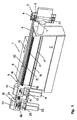
- a pipe bending machine 1 comprises a machine base 2, which is provided at a longitudinal end with a bending tool 3.
- the bending tool 3 is a conventional rotary bending tool that can be used for right / left bending and for Mehrrotebiegen. Instead of the rotary bending tool shown, other types of bending tools are conceivable.
- a bending template 4 and a clamping jaw 5 of the bending tool 3 clamp the front, already bent end of a tube 6.
- a slide 7 of the bending tool 3 is used in the usual way for the radial support of the tube 6 in the region of the transition of the undeformed in the bent pipe section.
- the tube 6 shown with circular cross section and hollow profiles with deviating from the circular cross-sectional shape can be edited on the pipe bending machine 1 with a corresponding choice of the bending tool 3.
- the remote from the bending tool 3 end of the tube 6 is fixed in a tube holder 8 in the form of a conventional chuck.
- the pipe holder 8 is part of a pipe feed 9 and as such attached to a carriage 10 of the pipe feed 9.
- a flanged to the carriage 10 electric motor 11 is used to drive the carriage 10 and the tube holder 8 with the clamped pipe 6 in the tube longitudinal direction 12.
- the electric motor 11 drives a gear 13 via a drive pinion 14, which in turn with a machine base body side Drive device 15 serving rack meshes.
- the tube holder 8 or the tube 6 is guided during the movement in the tube longitudinal direction 12 by means of a machine-body-side longitudinal guide device 16, which comprises two guide rails 17.
- On the carriage 10 mounted counter-guides 18 cooperate with the guide rails 17.
- a Dorn Wegzug 19 is designed. This comprises a mandrel 20 which projects through the carriage 10 and the tube holder 8 of the pipe feed 9 into the interior of the tube 6 and is provided at its end lying to the bending tool 3 end with a bending mandrel 21.
- the mandrel 21 takes his usual in the FIGS. 1 to 3 shown use position near the bending tool 3 and prevents in this way an undesirable cross-sectional deformation of the tube 6 in the region of the created pipe bend.
- Shortly before completion of the bending operation of the mandrel 21 is withdrawn by appropriate movement of the mandrel 20 in the tube longitudinal direction 12 from its position of use.
- the required longitudinal movement of the mandrel bar 20 is carried out by means of an electric motor 22 which is flanged to a carriage 23 of the mandrel retraction 19.
- the carriage 23 is provided with a mandrel bar holder 24, by means of the end remote from the bending tool 3 end of the mandrel bar 20 is releasably fixed.
- the electric motor 22 drives a drive gear 26 via a gear 25.
- the drive pinion 26 of the mandrel retraction 19 meshes with the rack or machine base body-side drive means 15.
- the pipe feed 9 and the mandrel bar retraction 19 are CNC controlled.
- the cars 10, 23 can be moved decoupled from each other.
- rack drives shown other drive types, in particular other drives with a machine base-side drive rod and / or with drive wheels on the carriages 10, 23, are conceivable.
- the still undeformed tube 6 is pushed in the initial state located in the open bending state 3 in the tube longitudinal direction 12 on the mandrel 20 and clamped with its rear end to the tube holder 8.
- the mandrel 21 may already be in its position of use at this time.
- the tube 6 is moved by moving the carriage 10 in the tube longitudinal direction 12 in the desired position. Subsequently, the bending tool 3 is closed and the tube 6 clamped between the bending template 4 and the clamping jaw 5. By subsequent rotation or pivoting movement of the bending template 4 and the jaw 5 is in the FIGS. 1 and 2 recognizable pipe bend created. Shortly before completion of the bending process, the mandrel 21 is transferred to a retracted position. In the FIGS. 1 to 3 the operating state is shown immediately before the onset of this withdrawal movement of the mandrel 21. To carry out the return movement of the bending mandrel 21, the carriage 23 of the mandrel retraction 19 is moved with the mandrel bar 20 held thereon correspondingly in the tube longitudinal direction 12.
- the bending tool 3 is first to be transferred to its opened initial state, and subsequently the tube 6 to be re-positioned by means of the pipe feed 9 in the tube longitudinal direction relative to the bending tool 3.
- the carriage 10 and the tube holder 8 then take the in Fig. 3 illustrated position.
- the bending mandrel 21 is to be converted by appropriate method of the carriage 23 with the mandrel rod holder 24 and the mandrel 20 to the bending tool 3 back to its position of use ( Fig. 3 ).
- the bending tool 3 can be closed and the tube 6, as in Fig. 3 represented, edited.
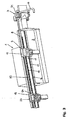
- a short tube 6a are processed, as shown in the FIGS. 4 and 5 is shown, is at the pipe bending machine 1 instead of the long mandrel 20 ( FIGS. 1 to 3 ) a short mandrel bar 20a ( FIGS. 4 . 5 ) used.
- the long mandrel 20 on the mandrel bar holder 24 is to be replaced with the short mandrel 20a.
- the carriage 10 with the tube holder 8 is located in the processing of the tube 6a near the bending tool side end of the machine body 2.
- the carriage 23 with the mandrel rod 20a fixed thereto follows the carriage 10 of the tube feed 9 in a bending tool near position.
Landscapes
- Engineering & Computer Science (AREA)
- Mechanical Engineering (AREA)
- Bending Of Plates, Rods, And Pipes (AREA)
Claims (9)
- Machine à cintrer des tubes comprenant :- un outil de cintrage (3),- une alimentation de tube (9) au moyen de laquelle un tube à cintrer (6, 6a) peut être positionné dans la direction longitudinale (12) du tube par rapport à l'outil de cintrage (3), et qui présente un dispositif de maintien de tube (8) guidé dans la direction longitudinale (12) du tube sur un dispositif de guidage longitudinal (16) prévu sur un bâti de machine (2) et mû, au moyen d'un entraînement d'alimentation de tube comprenant un dispositif d'entraînement (15) situé côté bâti de machine,- un dispositif de retrait du mandrin (19) qui permet de faire aller et venir dans la direction longitudinale (12) du tube, entre une position d'utilisation et une position de retrait, un mandrin de cintrage (21) fixé côté outil de cintrage sur une tige porte-mandrin (20, 20a) s'étendant dans la direction longitudinale (12) du tube, le dispositif de retrait du mandrin (19) présentant un support de tige porte-mandrin (24) prévu sur un chariot (23), qui est guidé dans la direction longitudinale (12) du tube sur le dispositif de guidage longitudinal (16) situé côté bâti de machine, et est mû, au moyen d'un entraînement de tige porte-mandrin comprenant un dispositif d'entraînement (15) situé côté bâti de machine,caractérisée en ce que, pour déplacer le support de tige porte-mandrin (24) dans la direction longitudinale (12) du tube, le chariot (23) peut être entraîné avec le support de tige porte-mandrin (24), dans la direction longitudinale (12) du tube, au moyen d'un moteur (22) prévu sur ledit chariot (23), et mû sur le dispositif d'entraînement (15) situé côté bâti de machine, et en ce que le dispositif de guidage longitudinal (16) situé côté bâti de machine pour le support de tige porte-mandrin (24) est formé par un dispositif de guidage longitudinal (16) situé côté bâti de machine pour le chariot (23) entraîné par moteur, qui est simultanément prévu en tant que dispositif de guidage longitudinal (16) situé côté bâti de machine pour le dispositif de maintien de tube (8).
- Machine à cintrer des tubes comprenant :- un outil de cintrage (3),- une alimentation de tube (9) au moyen de laquelle un tube à cintrer (6, 6a) peut être positionné dans la direction longitudinale (12) du tube par rapport à l'outil de cintrage (3), et qui présente un dispositif de maintien de tube (8) guidé dans la direction longitudinale (12) du tube sur un dispositif de guidage longitudinal (16) prévu sur un bâti de machine (2) et mû, au moyen d'un entraînement d'alimentation de tube comprenant un dispositif d'entraînement (15) situé côté bâti de machine,- un dispositif de retrait du mandrin (19) qui permet de faire aller et venir dans la direction longitudinale (12) du tube, entre une position d'utilisation et une position de retrait, un mandrin de cintrage (21) fixé côté outil de cintrage sur une tige porte-mandrin (20, 20a) s'étendant dans la direction longitudinale (12) du tube, le dispositif de retrait du mandrin (19) présentant un support de tige porte-mandrin (24) prévu sur un chariot (23), qui est guidé dans la direction longitudinale (12) du tube sur le dispositif de guidage longitudinal (16) situé côté bâti de machine, et est mû, au moyen d'un entraînement de tige porte-mandrin comprenant un dispositif d'entraînement (15) situé côté bâti de machine,caractérisée en ce que, pour déplacer le support de tige porte-mandrin (24) dans la direction longitudinale (12) du tube, le chariot (23) peut être entraîné avec le support de tige porte-mandrin (24) dans la direction longitudinale (12) du tube, au moyen d'un moteur (22) prévu sur ledit chariot (23), et mû sur le dispositif d'entraînement (15) situé côté bâti de machine, qui est simultanément prévu en tant que un dispositif d'entraînement (15) situé sur côté bâti de machine pour le dispositif de maintien de tube (8).
- Machine à cintrer des tubes selon la revendication 2, caractérisée en ce que le dispositif de guidage longitudinal (16) situé côté bâti de machine pour le support de tige porte-mandrin (24) est formé par un dispositif de guidage longitudinal (16) situé côté bâti de machine pour le chariot (23) entraîné par moteur, qui est simultanément prévu en tant que dispositif de guidage longitudinal (16) situé côté bâti de machine pour le dispositif de maintien de tube (8).
- Machine à cintrer des tubes selon l'une des revendications précédentes, caractérisée en ce que le dispositif de guidage longitudinal (16) situé côté bâti de machine qui est commun au support de la tige porte-mandrin (24) et au dispositif de maintien de tube (8) comporte au moins un rail de guidage (17).
- Machine à cintrer des tubes selon l'une des revendications précédentes, caractérisée en ce que l'entraînement de tige porte-mandrin et l'entraînement d'alimentation de tube sont réalisés en tant qu'entraînements à crémaillère, et en ce que le dispositif d'entraînement (15) situé côté bâti de machine, qui est commun au support de tige porte-mandrin (24) et au dispositif de maintien de tube (8), présente au moins une crémaillère avec laquelle engrènent au moins un pignon (26) situé côté support de tige porte-mandrin et au moins un pignon (14) situé côté dispositif de maintien de tube.
- Machine à cintrer des tubes selon l'une des revendications précédentes, caractérisée en ce que le support de tige porte-mandrin (24) et le dispositif de maintien de tube (8) sont chacun prévus sur un chariot (23, 10) guidé sur le dispositif de guidage longitudinal (16) commun situé côté bâti de machine et/ou entraîné sur le dispositif d'entraînement (15) commun situé côté bâti de machine.
- Machine à cintrer des tubes selon l'une des revendications précédentes, caractérisée en ce que le support de tige porte-mandrin (24) et/ou le dispositif de maintien de tube (8) peut (peuvent) être entraîné(s) sur le dispositif d'entraînement (15) commun situé côté bâti de machine, respectivement au moyen d'un entraînement de tige porte-mandrin et d'un entraînement d'alimentation de tube, respectivement comprenant au moins un moteur électrique (22) situé côté support de tige porte-mandrin et comprenant au moins un moteur électrique (11) situé côté dispositif de maintien de tube.
- Machine à cintrer des tubes selon l'une des revendications précédentes, caractérisée en ce que le support de tige porte-mandrin (24) et le dispositif de maintien de tube (8) peuvent être entraînés sur le dispositif d'entraînement (15) commun situé côté bâti de machine, au moyen d'un entraînement de tige porte-mandrin à commande numérique et d'un entraînement d'alimentation de tube à commande numérique.
- Machine à cintrer des tubes selon l'une des revendications précédentes, caractérisée en ce que la tige porte-mandrin (20, 20a) peut être retirée du support de tige porte-mandrin (24) pour être remplacée.
Priority Applications (4)
| Application Number | Priority Date | Filing Date | Title |
|---|---|---|---|
| ES02015760T ES2303540T3 (es) | 2002-07-13 | 2002-07-13 | Maquina de doblar tubos con herramienta de doblar y dispositivo de retroceso de mandril. |
| DE50211964T DE50211964D1 (de) | 2002-07-13 | 2002-07-13 | Rohrbiegemaschine mit Rohrvorschub und Dornrückzug |
| EP02015760A EP1380362B1 (fr) | 2002-07-13 | 2002-07-13 | Machine de cintrage de tubes avec alimentation de tubes et recul de mandrin |
| US10/618,245 US7082798B2 (en) | 2002-07-13 | 2003-07-11 | Pipe bending machine |
Applications Claiming Priority (1)
| Application Number | Priority Date | Filing Date | Title |
|---|---|---|---|
| EP02015760A EP1380362B1 (fr) | 2002-07-13 | 2002-07-13 | Machine de cintrage de tubes avec alimentation de tubes et recul de mandrin |
Publications (2)
| Publication Number | Publication Date |
|---|---|
| EP1380362A1 EP1380362A1 (fr) | 2004-01-14 |
| EP1380362B1 true EP1380362B1 (fr) | 2008-03-26 |
Family
ID=29724449
Family Applications (1)
| Application Number | Title | Priority Date | Filing Date |
|---|---|---|---|
| EP02015760A Expired - Lifetime EP1380362B1 (fr) | 2002-07-13 | 2002-07-13 | Machine de cintrage de tubes avec alimentation de tubes et recul de mandrin |
Country Status (4)
| Country | Link |
|---|---|
| US (1) | US7082798B2 (fr) |
| EP (1) | EP1380362B1 (fr) |
| DE (1) | DE50211964D1 (fr) |
| ES (1) | ES2303540T3 (fr) |
Families Citing this family (10)
| Publication number | Priority date | Publication date | Assignee | Title |
|---|---|---|---|---|
| ATE443597T1 (de) | 2007-06-29 | 2009-10-15 | Wafios Ag | Linearführung |
| ITRM20070483A1 (it) * | 2007-09-17 | 2009-03-18 | Cml Int Spa | Macchina curvatubi con anima avente una struttura portante particolarmente resistente alle sollecitazioni di loavorazione |
| DE102010013688B4 (de) * | 2010-04-01 | 2013-09-26 | Wafios Ag | Biegevorrichtung für längliche Werkstücke |
| CN103464550B (zh) * | 2012-06-06 | 2016-05-25 | 浙江摩多巴克斯科技股份有限公司 | 一种弯管机的管件推送装置 |
| USD755861S1 (en) * | 2014-08-15 | 2016-05-10 | Trumpf Gmbh + Co. Kg | Bending machine |
| JP1539124S (fr) * | 2014-08-15 | 2015-11-30 | ||
| CN108941286A (zh) * | 2017-05-18 | 2018-12-07 | 张家港市伯勤机械厂 | 一种自动弯管机 |
| CN109622691A (zh) * | 2018-12-07 | 2019-04-16 | 江苏现代造船技术有限公司 | 一种超长管弯管机 |
| IT202200012752A1 (it) * | 2022-06-16 | 2023-12-16 | Simat S R L | Macchina e procedimento per la produzione di prodotti tubolari piegati |
| CN117564144B (zh) * | 2024-01-16 | 2024-04-05 | 山东朝日不锈钢有限公司 | 一种弯管机用芯棒拉杆支撑装置及其方法 |
Family Cites Families (6)
| Publication number | Priority date | Publication date | Assignee | Title |
|---|---|---|---|---|
| FR2567429B1 (fr) * | 1984-07-10 | 1992-03-27 | Picot Sa | Machine pour le cintrage de tubes, barres ou profiles |
| EP0227779A1 (fr) | 1985-06-28 | 1987-07-08 | Integrated Production Machines Limited | Machine de cintrage de tuyaux |
| CH683598A5 (de) * | 1990-03-13 | 1994-04-15 | Mewag Maschinenfabrik Ag | Rohrbiegemaschine. |
| US5481891A (en) | 1993-12-20 | 1996-01-09 | Eagle Precision Technologies Inc. | Tube bending apparatus and method |
| FR2774317B1 (fr) * | 1998-01-30 | 2000-04-07 | Silfax | Machine a cintrer les tubes et son dispositif a barillet |
| US6155091A (en) * | 1999-02-26 | 2000-12-05 | Arvin Industries, Inc. | Mandrel assembly for tube-bending apparatus |
-
2002
- 2002-07-13 EP EP02015760A patent/EP1380362B1/fr not_active Expired - Lifetime
- 2002-07-13 ES ES02015760T patent/ES2303540T3/es not_active Expired - Lifetime
- 2002-07-13 DE DE50211964T patent/DE50211964D1/de not_active Expired - Lifetime
-
2003
- 2003-07-11 US US10/618,245 patent/US7082798B2/en not_active Expired - Lifetime
Also Published As
| Publication number | Publication date |
|---|---|
| EP1380362A1 (fr) | 2004-01-14 |
| US20050016239A1 (en) | 2005-01-27 |
| US7082798B2 (en) | 2006-08-01 |
| DE50211964D1 (de) | 2008-05-08 |
| ES2303540T3 (es) | 2008-08-16 |
Similar Documents
| Publication | Publication Date | Title |
|---|---|---|
| EP2177287B1 (fr) | Agencement de joues de support destiné au support latéral de coulissement de pièces usinées en forme de tiges ou de tubes sur des cintreuses | |
| DE4010445C2 (de) | Rohrbiegemaschine | |
| DE69202678T2 (de) | Multi-funktionnelle Rohrbiegemaschine. | |
| EP3645188B1 (fr) | Procédé de fabrication d'une pièce pliée et machine de pliage pour la mise en oeuvre du procédé | |
| DE69700915T2 (de) | Maschine zum biegen oder wölben von profilen und biegekopf für solche maschine | |
| DE102009030251B4 (de) | Lademagazin mit mitfahrendem Kanalsystem zum Be- und Entladen von Drehautomaten und System umfassend ein erstes und ein zweites Lademagazin sowie einen Drehautomaten | |
| EP0121077B1 (fr) | Machine à cintrer des tubes | |
| DE60205939T2 (de) | Bearbeitungsmaschine für langgestreckte profile | |
| EP1459816B1 (fr) | Dispostif de cintrage avec outil de cintrage à plusieurs niveaux, unité à machoires de serrage et unité de support à glissières pour un tel dispositif de cintrage | |
| EP2289643B1 (fr) | Dispositif pour le pliage de longues pièces usinées | |
| CH696843A5 (de) | Werkzeugmaschine zur Laserstrahlbearbeitung von länglichen Werkstücken. | |
| DE1920670C3 (de) | Numerisch gesteuerte Rohrbiegemaschine | |
| EP1350577A1 (fr) | Machine de pliage des pièces en forme de barre ou tige, en particulier des tubes | |
| DE3017613A1 (de) | Werkzeugwechselvorrichtung fuer eine werkzeugmaschine | |
| DE102009024406B4 (de) | Rotationsbiegewerkzeug mit Exzenterklemmung | |
| EP1380362A1 (fr) | Machine de cintrage de tubes avec alimentation de tubes et recul de mandrin | |
| EP1210995A1 (fr) | Machine pour l'usinage de pièces, notamment de tôles, avec au moins un dispositif de cintrage et un dispositif d'assemblage | |
| DE69805550T2 (de) | Rohrbiegevorrichtung und ihre trommeleinrichtung | |
| EP2475474B1 (fr) | Machine de pliage pour plier des pièces allongées notamment des tubes ou des profilés | |
| DE10338938B4 (de) | Vorschubvorrichtung für Walzgut und Verfahren zum Vorschieben eines Walzguts | |
| EP3389888A1 (fr) | Presse à cintrer munie d'un dispositif de changement d'outil | |
| EP1914021B1 (fr) | Machine de cintrage de barres et/ou de pièces en forme de tige, en particulier de tubes et outil pour cette machine | |
| EP0362698A2 (fr) | Machine pour le cintrage automatique de tubes et objets similaires | |
| EP1350578B1 (fr) | Machine de pliage des pièces en forme de barre et/ou tige, en particulier des tubes | |
| DE10229652B4 (de) | Schlitten für Rohrbiegemaschine |
Legal Events
| Date | Code | Title | Description |
|---|---|---|---|
| PUAI | Public reference made under article 153(3) epc to a published international application that has entered the european phase |
Free format text: ORIGINAL CODE: 0009012 |
|
| AK | Designated contracting states |
Kind code of ref document: A1 Designated state(s): AT BE BG CH CY CZ DE DK EE ES FI FR GB GR IE IT LI LU MC NL PT SE SK TR |
|
| AX | Request for extension of the european patent |
Extension state: AL LT LV MK RO SI |
|
| 17P | Request for examination filed |
Effective date: 20040708 |
|
| AKX | Designation fees paid |
Designated state(s): CH DE ES FR GB IT LI |
|
| RAP1 | Party data changed (applicant data changed or rights of an application transferred) |
Owner name: TRUMPF WERKZEUGMASCHINEN GMBH + CO. KG |
|
| GRAP | Despatch of communication of intention to grant a patent |
Free format text: ORIGINAL CODE: EPIDOSNIGR1 |
|
| GRAJ | Information related to disapproval of communication of intention to grant by the applicant or resumption of examination proceedings by the epo deleted |
Free format text: ORIGINAL CODE: EPIDOSDIGR1 |
|
| GRAP | Despatch of communication of intention to grant a patent |
Free format text: ORIGINAL CODE: EPIDOSNIGR1 |
|
| GRAS | Grant fee paid |
Free format text: ORIGINAL CODE: EPIDOSNIGR3 |
|
| GRAA | (expected) grant |
Free format text: ORIGINAL CODE: 0009210 |
|
| AK | Designated contracting states |
Kind code of ref document: B1 Designated state(s): CH DE ES FR GB IT LI |
|
| REG | Reference to a national code |
Ref country code: GB Ref legal event code: FG4D Free format text: NOT ENGLISH |
|
| REG | Reference to a national code |
Ref country code: CH Ref legal event code: EP |
|
| REF | Corresponds to: |
Ref document number: 50211964 Country of ref document: DE Date of ref document: 20080508 Kind code of ref document: P |
|
| REG | Reference to a national code |
Ref country code: ES Ref legal event code: FG2A Ref document number: 2303540 Country of ref document: ES Kind code of ref document: T3 |
|
| ET | Fr: translation filed | ||
| PLBE | No opposition filed within time limit |
Free format text: ORIGINAL CODE: 0009261 |
|
| STAA | Information on the status of an ep patent application or granted ep patent |
Free format text: STATUS: NO OPPOSITION FILED WITHIN TIME LIMIT |
|
| 26N | No opposition filed |
Effective date: 20081230 |
|
| REG | Reference to a national code |
Ref country code: DE Ref legal event code: R097 Ref document number: 50211964 Country of ref document: DE |
|
| REG | Reference to a national code |
Ref country code: DE Ref legal event code: R040 Ref document number: 50211964 Country of ref document: DE Effective date: 20121106 |
|
| PGFP | Annual fee paid to national office [announced via postgrant information from national office to epo] |
Ref country code: GB Payment date: 20150724 Year of fee payment: 14 Ref country code: ES Payment date: 20150723 Year of fee payment: 14 Ref country code: CH Payment date: 20150723 Year of fee payment: 14 |
|
| REG | Reference to a national code |
Ref country code: FR Ref legal event code: PLFP Year of fee payment: 15 |
|
| REG | Reference to a national code |
Ref country code: CH Ref legal event code: PL |
|
| GBPC | Gb: european patent ceased through non-payment of renewal fee |
Effective date: 20160713 |
|
| PG25 | Lapsed in a contracting state [announced via postgrant information from national office to epo] |
Ref country code: CH Free format text: LAPSE BECAUSE OF NON-PAYMENT OF DUE FEES Effective date: 20160731 Ref country code: LI Free format text: LAPSE BECAUSE OF NON-PAYMENT OF DUE FEES Effective date: 20160731 |
|
| PG25 | Lapsed in a contracting state [announced via postgrant information from national office to epo] |
Ref country code: GB Free format text: LAPSE BECAUSE OF NON-PAYMENT OF DUE FEES Effective date: 20160713 |
|
| REG | Reference to a national code |
Ref country code: FR Ref legal event code: PLFP Year of fee payment: 16 |
|
| PG25 | Lapsed in a contracting state [announced via postgrant information from national office to epo] |
Ref country code: ES Free format text: LAPSE BECAUSE OF NON-PAYMENT OF DUE FEES Effective date: 20160714 |
|
| REG | Reference to a national code |
Ref country code: FR Ref legal event code: PLFP Year of fee payment: 17 |
|
| REG | Reference to a national code |
Ref country code: ES Ref legal event code: FD2A Effective date: 20181129 |
|
| PGFP | Annual fee paid to national office [announced via postgrant information from national office to epo] |
Ref country code: DE Payment date: 20200721 Year of fee payment: 19 Ref country code: FR Payment date: 20200721 Year of fee payment: 19 |
|
| PGFP | Annual fee paid to national office [announced via postgrant information from national office to epo] |
Ref country code: IT Payment date: 20200724 Year of fee payment: 19 |
|
| REG | Reference to a national code |
Ref country code: DE Ref legal event code: R119 Ref document number: 50211964 Country of ref document: DE |
|
| PG25 | Lapsed in a contracting state [announced via postgrant information from national office to epo] |
Ref country code: DE Free format text: LAPSE BECAUSE OF NON-PAYMENT OF DUE FEES Effective date: 20220201 |
|
| PG25 | Lapsed in a contracting state [announced via postgrant information from national office to epo] |
Ref country code: FR Free format text: LAPSE BECAUSE OF NON-PAYMENT OF DUE FEES Effective date: 20210731 |
|
| PG25 | Lapsed in a contracting state [announced via postgrant information from national office to epo] |
Ref country code: IT Free format text: LAPSE BECAUSE OF NON-PAYMENT OF DUE FEES Effective date: 20210713 |