EP1051899A2 - Erntegerät insbesondere zum Sammeln von Oliven oder dergleichen landwirtschaftlichen Produkte - Google Patents
Erntegerät insbesondere zum Sammeln von Oliven oder dergleichen landwirtschaftlichen Produkte Download PDFInfo
- Publication number
- EP1051899A2 EP1051899A2 EP00110133A EP00110133A EP1051899A2 EP 1051899 A2 EP1051899 A2 EP 1051899A2 EP 00110133 A EP00110133 A EP 00110133A EP 00110133 A EP00110133 A EP 00110133A EP 1051899 A2 EP1051899 A2 EP 1051899A2
- Authority
- EP
- European Patent Office
- Prior art keywords
- tool according
- section
- articulation
- slide valve
- tool
- Prior art date
- Legal status (The legal status is an assumption and is not a legal conclusion. Google has not performed a legal analysis and makes no representation as to the accuracy of the status listed.)
- Withdrawn
Links
- 241000207836 Olea <angiosperm> Species 0.000 title claims abstract description 9
- 238000003306 harvesting Methods 0.000 title claims abstract description 7
- 230000008878 coupling Effects 0.000 claims abstract description 6
- 238000010168 coupling process Methods 0.000 claims abstract description 6
- 238000005859 coupling reaction Methods 0.000 claims abstract description 6
- 229920001971 elastomer Polymers 0.000 claims description 7
- 239000000806 elastomer Substances 0.000 claims description 7
- 229920000642 polymer Polymers 0.000 claims description 4
- 238000007789 sealing Methods 0.000 claims description 4
- 229910001220 stainless steel Inorganic materials 0.000 claims description 3
- 239000010935 stainless steel Substances 0.000 claims description 3
- 239000002390 adhesive tape Substances 0.000 claims description 2
- 230000002860 competitive effect Effects 0.000 description 2
- 230000000670 limiting effect Effects 0.000 description 2
- 238000005516 engineering process Methods 0.000 description 1
- 238000001746 injection moulding Methods 0.000 description 1
- 230000010354 integration Effects 0.000 description 1
- 238000004519 manufacturing process Methods 0.000 description 1
- 239000000463 material Substances 0.000 description 1
- 230000004048 modification Effects 0.000 description 1
- 238000012986 modification Methods 0.000 description 1
- 230000009467 reduction Effects 0.000 description 1
Images


Classifications
-
- A—HUMAN NECESSITIES
- A01—AGRICULTURE; FORESTRY; ANIMAL HUSBANDRY; HUNTING; TRAPPING; FISHING
- A01D—HARVESTING; MOWING
- A01D46/00—Picking of fruits, vegetables, hops, or the like; Devices for shaking trees or shrubs
- A01D46/26—Devices for shaking trees or shrubs; Fruit catching devices to be used therewith
- A01D46/264—Devices for beating or vibrating the foliage; Fruit catching devices to be used therewith
-
- A—HUMAN NECESSITIES
- A01—AGRICULTURE; FORESTRY; ANIMAL HUSBANDRY; HUNTING; TRAPPING; FISHING
- A01D—HARVESTING; MOWING
- A01D46/00—Picking of fruits, vegetables, hops, or the like; Devices for shaking trees or shrubs
- A01D46/26—Devices for shaking trees or shrubs; Fruit catching devices to be used therewith
- A01D2046/266—Portable devices to shake branches
-
- A—HUMAN NECESSITIES
- A01—AGRICULTURE; FORESTRY; ANIMAL HUSBANDRY; HUNTING; TRAPPING; FISHING
- A01D—HARVESTING; MOWING
- A01D46/00—Picking of fruits, vegetables, hops, or the like; Devices for shaking trees or shrubs
- A01D46/26—Devices for shaking trees or shrubs; Fruit catching devices to be used therewith
- A01D2046/268—Devices to shake the branches pneumatically powered
Definitions
- the present invention relates to a harvesting tool, particularly for knocking down or gathering olives or similar agricultural products.
- Each one of said sectors has a corresponding rake-like plurality of rods which, as they move, grip the agricultural product (typically olives).
- the aim of the present invention is to provide a harvesting tool, particularly for knocking down or gathering olives or similar agricultural products, which solves the above-described drawbacks in currently commercially available tools having the same functions, and which in particular is provided with a structure which is balanced from the point of view of masses and allows easy operation without particular efforts for the operator.
- an important object of the present invention is to provide a tool in which the actuation means are actuated practically exclusively with regard to their particular movement function.
- Another object of the present invention is to provide a tool which is functionally valid, constructively simple and reliable as a whole.
- Another object of the present invention is to provide a tool which is highly flexible in use.
- Another object of the present invention is to provide a tool which can be manufactured with conventional technologies and at costs which are competitive with respect to tools having similar functions.
- a harvesting tool particularly for gathering olives or similar agricultural products, of the type that comprises two mutually opposite oscillating sectors which are articulated to a supporting body and are connected to actuation means, a corresponding series of rods being fixed to each one of said sectors in a rake-like arrangement, said tool being characterized in that said body comprises three sections: a first section for supporting said sectors; a second section for coupling to said actuation means; and a third section for connection to a handling pole which is articulated by way of a hinge-type articulation including an internal duct for the passage of supply air for said actuation means, which are constituted by at least one pneumatic cylinder.
- a harvesting tool particularly for knocking down or gathering olives or similar agricultural products, according to the present invention, is generally designated by the reference numeral 10.
- the tool 10 comprises two mutually opposite oscillating sectors 12 which are articulated to a supporting body 11 made of an engineering polymer and are connected to actuation means, generally designated by the reference numeral 13, to each of which a corresponding rake-like plurality of rods 14 is fixed.
- the body 11 made of engineering polymer comprises, in this case, three sections: a first section 15 for the articulation of said sectors 12; a second section 16 for coupling to the actuation means 13; and a third section 17 for connection to a handling pole 18.
- the pole 18 and the third section 17 are mutually articulated by way of a hinge-like articulation 19.
- An internal duct 20 (see Figure 3) is provided in the articulation 19 for the passage of supply air for the actuation means 13, which in this case are constituted by a pneumatic cylinder generally designated by the reference numeral 21.
- the duct 20 is composed of portions 20a and 20b, which lie respectively in the portions 19a and 19b of the articulation 19, and portions 20c and 20d, which lie within the section 16 (see Figure 5).
- a filter 20e is arranged in the first portion 20a.
- a semicircular recess 22 which is formed in the articulation 19 for connection between the portions 20a and 20b, and an elastomer ring 23 is placed in order to produce a seal.
- a friction disk 19c is interposed which increases the friction between the surfaces, facilitating their mutual locking, which is provided by the pivoting bolt 19d.
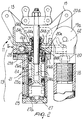
- the double-acting cylinder 21 (see Figure 2) comprises a piston 24 which can slide in a lapped metallic jacket 25a which is rigidly coupled to, and placed in, a body 25 and is closed at its ends by heads, respectively a main head 26 which is monolithic with respect to the body 11 and a secondary head 27 which lies opposite thereto.
- the stem 24a of the piston 24 is guided, in its reciprocating movement, by a bush 24b which is shaped so as to accommodate an antifriction and self-lubricating bearing 24c, a sealing gasket and scraper ring 24e, and two sealing gaskets 24f at a groove 20e which acts as a manifold for the passage of air from the duct 20d to the recess 28 of the slide valve 31 and cools the portion affected by the sliding of the stem 24a.
- Elastomer pads designated by the reference numerals 26a and 27a respectively, for providing a cushioned stroke limit, are present in the heads 26 and 27 of the cylinder 21.
- the seat of said pad 26a is located in the bush 24b.
- a stainless steel plate 25b is interposed between the head of the body 25 and the main head 26 and ensures flatness in case of uneven regions produced by the injection-molding of the two components and the seal with elastomer gaskets 26b which are arranged in the main head 26 in the air passage regions.
- the plate 25b constitutes the sliding surface for the secondary plate of the slide valve 31 which will be described in greater detail hereinafter.
- a double-adhesive tape is interposed between the plate 25b and the body 25.
- An elliptical recess 28 is formed in the main head 26 (which is a part of the section 16) and is connected to two mutually opposite lapped coaxial cylindrical seats 29 and 30 for accommodating, as a whole, a five-way slide valve 31 which is laterally axially offset with respect to the axis of the cylinder 21.
- the cylindrical seats 29 and 30 lead to opposite positions of the main head 26 and are closed by screwed-on plugs 29a and 30a, each of which is provided with an elastomer pad 20b and 30b for providing a cushioned stroke limit for the slide valve 31.
- the articulation 19, in this embodiment, lies proximate to the articulation 32 of one of the two sectors 12 to the body 11 and lies opposite the slide valve 31 with respect to the axis of the cylinder 21.
- Supply ducts 33, 34 and 35 are also formed in said cylinder 21 and partially in the main head 26 and, by intersecting with respective end ducts, switch the supplies between the slide valve 31 and the cylinder 21 and viceversa.
- the main head 26 is monolithic to the body 11 and the portions 20c and 20d (see Figure 5) of the duct for connecting the air supply between the articulation 19 and said slide valve 31 are provided therein.
- Said slide valve is constituted by a cylindrical element 31a, which can slide in the seats 29 and 30, and by an elliptical secondary plate 31b which is rigidly coupled thereto and is arranged adjacent to the plate 25b and to the outlets of the ducts 33, 34 and 35 formed therein.
- the secondary plate 31b has a concave portion 31e which comprises the space between two consecutive outlets in order to alternately connect them.
- the coupling between the cylindrical element 31a and the secondary plate 31b is provided by a tab 31c which has an H-shaped cross-section, protrudes from said secondary plate and enters a complementarily shaped seat 31d of the cylindrical element.
- the two mutually opposite wings of the H-shaped cross-section are perpendicular to the sliding axis of the slide valve 31.
- the cylindrical element 31a determines, during sliding, traction in both directions with the two wings of the H-shaped cross-section of the tab 31c which act proximate to the sliding surface, minimizing the torsional components and allowing adhesion, and therefore an annular seal, on the exchange surface of the distribution circuit.
- the articulation can be locked at preset angles of inclination thanks to the presence, in the portions 19a and 19b of the articulation 19, of through holes 37a and 37b for a pin 40.
- the holes 37b are distributed along respective circular arcs which subtend angles of 30 sexagesimal degrees.
- the pin 40 can be inserted through the holes 37a and 37b that are arranged coaxially.
- the articulation 19 has, in the portion 19a, a semicircular groove 38 for limiting the movement arc by means of a grub screw 39 which is screwed in a corresponding hole 41 of the portion 19b.
- the structure of the tool according to the invention is particularly balanced in terms of masses, allowing easy handling by the operator.
- the main head by being monolithic with the supporting body, also facilitates the reduction of space occupation.
- the materials and the dimensions may be any according to requirements.
Landscapes
- Life Sciences & Earth Sciences (AREA)
- Environmental Sciences (AREA)
- Check Valves (AREA)
- Harvesting Machines For Specific Crops (AREA)
Applications Claiming Priority (4)
| Application Number | Priority Date | Filing Date | Title |
|---|---|---|---|
| ITPD990102 | 1999-05-13 | ||
| ITPD990102 IT1306657B1 (it) | 1999-05-13 | 1999-05-13 | Attrezzo particolarmente per l'abbacchiatura di olive o similiprodotti agricoli. |
| ITPD990251 | 1999-11-11 | ||
| ITPD990251 IT1306687B1 (it) | 1999-11-11 | 1999-11-11 | Attrezzo particolarmente per l'abbacchiatura di olive o similiprodotti agricoli. |
Publications (2)
| Publication Number | Publication Date |
|---|---|
| EP1051899A2 true EP1051899A2 (de) | 2000-11-15 |
| EP1051899A3 EP1051899A3 (de) | 2001-10-31 |
Family
ID=26331884
Family Applications (1)
| Application Number | Title | Priority Date | Filing Date |
|---|---|---|---|
| EP00110133A Withdrawn EP1051899A3 (de) | 1999-05-13 | 2000-05-11 | Erntegerät insbesondere zum Sammeln von Oliven oder dergleichen landwirtschaftlichen Produkte |
Country Status (1)
| Country | Link |
|---|---|
| EP (1) | EP1051899A3 (de) |
Cited By (8)
| Publication number | Priority date | Publication date | Assignee | Title |
|---|---|---|---|---|
| EP1273222A1 (de) * | 2001-06-28 | 2003-01-08 | Zanon S.n.c. di Zanon Franco E C. | Erntegerät insbesondere für Oliven oder dergleichen landwirtschaftlichen Produkte |
| EP1323342A1 (de) * | 2001-11-30 | 2003-07-02 | Pasquale Travaglini | Manuelle pneumatische Rüttelvorrichtung mit bidirektionalem orthogonalem Antrieb |
| EP1621063A3 (de) * | 2004-07-30 | 2006-03-29 | Zanon S.R.L. | Erntegerät insbesondere für Oliven oder dergleichen landwirtschaftlichen Produkte |
| IT201700018805A1 (it) * | 2017-02-20 | 2018-08-20 | Giancarlo Fedeli | Apparecchio battitore per il distacco di frutti da alberi da frutto |
| EP3363278A1 (de) * | 2017-02-20 | 2018-08-22 | Giancarlo Fedeli | Erntegerät zum ernten von produkten aus obstbäumen |
| CN108718692A (zh) * | 2018-07-18 | 2018-11-02 | 昆明理工大学 | 一种便携式采摘包装一体机 |
| IT201800002697A1 (it) * | 2018-02-15 | 2019-08-15 | Giancarlo Fedeli | Apparecchio battitore per il distacco di frutti da alberi da frutto |
| IT202100023612A1 (it) * | 2021-09-14 | 2023-03-14 | Sbaraglia S R L | Abbacchiatore pneumatico |
Citations (2)
| Publication number | Priority date | Publication date | Assignee | Title |
|---|---|---|---|---|
| ITPD990102A1 (it) | 1999-05-13 | 2000-11-13 | Zanon Snc Di Zanon Franco E C | Attrezzo particolarmente per l'abbacchiatura di olive o simili prodotti agricoli |
| ITPD990251A1 (it) | 1999-11-11 | 2001-05-11 | Zanon Snc Di Zanon Franco E C | Attrezzo particolarmente per l'abbacchiatura di olive o similiprodotti agricoli |
Family Cites Families (6)
| Publication number | Priority date | Publication date | Assignee | Title |
|---|---|---|---|---|
| GB851475A (en) * | 1956-04-04 | 1960-10-19 | Joseph Rawlings | Improvements in means for gripping and moving articles |
| FR2327719A1 (fr) * | 1975-10-13 | 1977-05-13 | Lendaro Ernesto | Perfectionnement aux appareils portatifs pour battre les branches des plantes au moyen de tiges a secousses |
| IT1295122B1 (it) * | 1997-02-26 | 1999-04-30 | Nicola Buonora | Attrezzo per causare la caduta di olive,mandorle e altri frutti similari dalla chioma di un albero, mediante spazzole oscillanti. |
| IT1305936B1 (it) * | 1998-02-25 | 2001-05-21 | Michele Troiano | Attrezzo vibratore portatile per la raccolta di olive,mandorle,caffe',e altri frutti in genere. |
| IT1309684B1 (it) * | 1999-03-31 | 2002-01-30 | Campagnola Srl | Attuatore pneumatico per la movimentazione di organi operativi, inparticolare pettini per la raccolta di frutta |
| IT1310481B1 (it) * | 1999-09-17 | 2002-02-18 | Campagnola Srl | Attuatore pneumatico per la movimentazione di organi operativi. |
-
2000
- 2000-05-11 EP EP00110133A patent/EP1051899A3/de not_active Withdrawn
Patent Citations (2)
| Publication number | Priority date | Publication date | Assignee | Title |
|---|---|---|---|---|
| ITPD990102A1 (it) | 1999-05-13 | 2000-11-13 | Zanon Snc Di Zanon Franco E C | Attrezzo particolarmente per l'abbacchiatura di olive o simili prodotti agricoli |
| ITPD990251A1 (it) | 1999-11-11 | 2001-05-11 | Zanon Snc Di Zanon Franco E C | Attrezzo particolarmente per l'abbacchiatura di olive o similiprodotti agricoli |
Cited By (8)
| Publication number | Priority date | Publication date | Assignee | Title |
|---|---|---|---|---|
| EP1273222A1 (de) * | 2001-06-28 | 2003-01-08 | Zanon S.n.c. di Zanon Franco E C. | Erntegerät insbesondere für Oliven oder dergleichen landwirtschaftlichen Produkte |
| EP1323342A1 (de) * | 2001-11-30 | 2003-07-02 | Pasquale Travaglini | Manuelle pneumatische Rüttelvorrichtung mit bidirektionalem orthogonalem Antrieb |
| EP1621063A3 (de) * | 2004-07-30 | 2006-03-29 | Zanon S.R.L. | Erntegerät insbesondere für Oliven oder dergleichen landwirtschaftlichen Produkte |
| IT201700018805A1 (it) * | 2017-02-20 | 2018-08-20 | Giancarlo Fedeli | Apparecchio battitore per il distacco di frutti da alberi da frutto |
| EP3363278A1 (de) * | 2017-02-20 | 2018-08-22 | Giancarlo Fedeli | Erntegerät zum ernten von produkten aus obstbäumen |
| IT201800002697A1 (it) * | 2018-02-15 | 2019-08-15 | Giancarlo Fedeli | Apparecchio battitore per il distacco di frutti da alberi da frutto |
| CN108718692A (zh) * | 2018-07-18 | 2018-11-02 | 昆明理工大学 | 一种便携式采摘包装一体机 |
| IT202100023612A1 (it) * | 2021-09-14 | 2023-03-14 | Sbaraglia S R L | Abbacchiatore pneumatico |
Also Published As
| Publication number | Publication date |
|---|---|
| EP1051899A3 (de) | 2001-10-31 |
Similar Documents
| Publication | Publication Date | Title |
|---|---|---|
| EP1051899A2 (de) | Erntegerät insbesondere zum Sammeln von Oliven oder dergleichen landwirtschaftlichen Produkte | |
| US4946204A (en) | Snap swivel coupling for fluid flow applications | |
| US9394936B2 (en) | Ball joint | |
| US5537929A (en) | Article carrying apparatus | |
| KR100462130B1 (ko) | 신축붐용신축부품안내장치 | |
| US7390026B2 (en) | Housing type joint | |
| US7699355B2 (en) | Variable-angle tubular connection | |
| GB2311034A (en) | Handle for a concrete float | |
| CN101165281B (zh) | 用于销式抓斗器具的间距组件和使用该间距组件的器具组件 | |
| US20140083232A1 (en) | Parallel link robot connected by ball joints | |
| CA2473891A1 (en) | Joint for connecting components together on opposite longitudinal sides in addition to a flexible strip used for said joint | |
| US20050056114A1 (en) | Cable or the like protection and guide device | |
| TW201202578A (en) | Fluid pressure apparatus | |
| CA1100457A (en) | Closing member for a ring valve | |
| US4449863A (en) | Pipe switch for pneumatic conveying devices | |
| JP2022537510A (ja) | クリーンルーム用途のためのサポートチェーンを有するラインガイド及びそのためのサポートチェーン | |
| EP1051900B1 (de) | Erntegerät insbesondere zum Sammeln von Oliven oder dergleichen landwirtschaftlichen Produkte | |
| JPH0346684B2 (de) | ||
| WO2004092614A1 (en) | Cable chain | |
| EP1273222A1 (de) | Erntegerät insbesondere für Oliven oder dergleichen landwirtschaftlichen Produkte | |
| US4968003A (en) | Diaphragm valve | |
| EP0999399B1 (de) | Mehrwegedrehkupplung zum Verbinden von einem druckmittelbetriebenen Werkzeug an eine Fluidquelle | |
| US10781951B2 (en) | Anti-binding ball swivel | |
| JP6901601B2 (ja) | 構成物ハウジングおよび接続ブロックを持つ油圧構成物 | |
| US5498095A (en) | Press fitted flexural pivot joint |
Legal Events
| Date | Code | Title | Description |
|---|---|---|---|
| PUAI | Public reference made under article 153(3) epc to a published international application that has entered the european phase |
Free format text: ORIGINAL CODE: 0009012 |
|
| AK | Designated contracting states |
Kind code of ref document: A2 Designated state(s): AT BE CH CY DE DK ES FI FR GB GR IE IT LI LU MC NL PT SE |
|
| AX | Request for extension of the european patent |
Free format text: AL;LT;LV;MK;RO;SI |
|
| PUAL | Search report despatched |
Free format text: ORIGINAL CODE: 0009013 |
|
| AK | Designated contracting states |
Kind code of ref document: A3 Designated state(s): AT BE CH CY DE DK ES FI FR GB GR IE IT LI LU MC NL PT SE |
|
| AX | Request for extension of the european patent |
Free format text: AL;LT;LV;MK;RO;SI |
|
| RIC1 | Information provided on ipc code assigned before grant |
Free format text: 7A 01D 46/24 A, 7A 01D 46/26 B |
|
| 17P | Request for examination filed |
Effective date: 20020322 |
|
| AKX | Designation fees paid |
Free format text: AT BE CH CY DE DK ES FI FR GB GR IE IT LI LU MC NL PT SE |
|
| RAP1 | Party data changed (applicant data changed or rights of an application transferred) |
Owner name: ZANON S.R.L. |
|
| STAA | Information on the status of an ep patent application or granted ep patent |
Free format text: STATUS: THE APPLICATION IS DEEMED TO BE WITHDRAWN |
|
| 18D | Application deemed to be withdrawn |
Effective date: 20080625 |