EP1051981A1 - Stapelbare Trägerplatten für Sterilisierungen und Behälter dafür - Google Patents
Stapelbare Trägerplatten für Sterilisierungen und Behälter dafür Download PDFInfo
- Publication number
- EP1051981A1 EP1051981A1 EP00401259A EP00401259A EP1051981A1 EP 1051981 A1 EP1051981 A1 EP 1051981A1 EP 00401259 A EP00401259 A EP 00401259A EP 00401259 A EP00401259 A EP 00401259A EP 1051981 A1 EP1051981 A1 EP 1051981A1
- Authority
- EP
- European Patent Office
- Prior art keywords
- lights
- sterilization
- type
- cover
- sterilization tray
- Prior art date
- Legal status (The legal status is an assumption and is not a legal conclusion. Google has not performed a legal analysis and makes no representation as to the accuracy of the status listed.)
- Withdrawn
Links
Images


Classifications
-
- A—HUMAN NECESSITIES
- A61—MEDICAL OR VETERINARY SCIENCE; HYGIENE
- A61L—METHODS OR APPARATUS FOR STERILISING MATERIALS OR OBJECTS IN GENERAL; DISINFECTION, STERILISATION OR DEODORISATION OF AIR; CHEMICAL ASPECTS OF BANDAGES, DRESSINGS, ABSORBENT PADS OR SURGICAL ARTICLES; MATERIALS FOR BANDAGES, DRESSINGS, ABSORBENT PADS OR SURGICAL ARTICLES
- A61L2/00—Disinfection or sterilisation of materials or objects, in general; Accessories therefor
- A61L2/26—Accessories
-
- A—HUMAN NECESSITIES
- A61—MEDICAL OR VETERINARY SCIENCE; HYGIENE
- A61B—DIAGNOSIS; SURGERY; IDENTIFICATION
- A61B50/00—Containers, covers, furniture or holders specially adapted for surgical or diagnostic appliances or instruments, e.g. sterile covers
- A61B50/30—Containers specially adapted for packaging, protecting, dispensing, collecting or disposing of surgical or diagnostic appliances or instruments
- A61B50/33—Trays
-
- A—HUMAN NECESSITIES
- A61—MEDICAL OR VETERINARY SCIENCE; HYGIENE
- A61L—METHODS OR APPARATUS FOR STERILISING MATERIALS OR OBJECTS IN GENERAL; DISINFECTION, STERILISATION OR DEODORISATION OF AIR; CHEMICAL ASPECTS OF BANDAGES, DRESSINGS, ABSORBENT PADS OR SURGICAL ARTICLES; MATERIALS FOR BANDAGES, DRESSINGS, ABSORBENT PADS OR SURGICAL ARTICLES
- A61L2103/00—Materials or objects being the target of disinfection or sterilisation
- A61L2103/15—Laboratory, medical or dentistry appliances, e.g. catheters or sharps
Definitions
- the present invention relates to the field of medical equipment, especially trays sterilization equipment fitted to support instrumentation medical.
- Such trays are commonly used by surgeons or associated assistants to transport on the operating site medical instrumentation in related to the intervention concerned.
- the tray is arranged to support various instruments, for example clamps, endoscopes etc. which are more or less fragile.
- These trays must be made to be able endure, after use, the usual phases of cleaning, in accordance with a decontamination and sterilization as is the practice in the medical field.
- the invention relates more particularly to a sterilization tray fitted to support a medical instrumentation, consisting of a tank with upper two plates forming handles, said plates being surmounted by projecting studs used to hang a covering cover fitted for this purpose with associated lights, in accordance with the preamble to the claim 1.
- the rigid studs are made in the form of metal nipples riveted or screwed onto the plates forming handles, so that even with precise machining of cover lights, one cannot achieve a hold truly reliable cover in the hooked position of it.
- These sterilization trays can be possibly superimposed, so that they comprise usually centering pads so as to be stackable in a stack which can be arranged at inside a container. It has thus been proposed containers with a compartment for three stacked trays.
- the compartment is usually dimensioned so that the three trays are exactly received inside the compartment, without risk for detaching a tray or lid closing the upper shelf.
- the container is opened, when the operator clears the upper tray, it may be that by an awkward movement a shock is exerted on the cover and slide it over the relevant container and do not more protects the inside of the tray.
- the object of the invention is to improve the structure such sterilization trays to avoid aforementioned drawbacks.
- the object of the invention is therefore to design a sterilization tray whose structure allows both reliable locking of its cover, while allowing combinations of overlays of various types, with also the possibility of locking between them the superimposed trays.
- each handle plate is equipped with at least a hanging stud constituted by a foot at least in part made of flexible material and by a head more wide above said foot, and in which the cover additionally has at least one light at one end opening of a first type presenting a constriction intermediate forming a hard point passage for the foot of the relevant attachment stud, and at its opposite end at least one non-emerging light of a second type having the shape of a keyhole, the part of which wide allows the passage of the head of the attachment stud concerned and the narrow part the sliding of the foot of said stud, in accordance with the characterizing part of the claim 1.
- the foot of each attachment stud is formed by a rigid baluster surrounded over its entire height a sleeve made of flexible material, for example silicone, and the enlarged head of the attachment stud is one piece with the baluster, with a central thread for the fixing of said stud on the dish concerned.
- This mode of construction allows the sleeve to be replaced if necessary in flexible material in the event of premature wear thereof, while retaining the basic metallic structure constituting the attachment studs.
- each dish of the tray is equipped of two attachment pads, the four pads of said tray being identical and positioned in a rectangle.
- the or each light opening of the first type has an intermediate tightening which is sandwiched between an input part whose the width decreases towards said constriction and a substantially circular bottom part.
- the entrance part is defined by two straight sections inclined towards each other, connecting to two parallel straight sections that form the tightening intermediate.
- the passage width of the intermediate tightening is significantly less than outside diameter of the foot of the attachment stud concerned, and the diameter of the bottom part is substantially equal said outside diameter.
- the or each light non-opening of the second type has a wide part circular whose diameter is sufficient for the passage of the head of the attachment block concerned, and a part narrow whose width is constant and appreciably equal to the outside diameter of the base of said stud.
- the cover has a pair of lights at one end of the first type and at the other end a pair of lights of the second type, these four lights being positioned in a rectangle.
- the bin has a bottom which is equipped with lights of the first and second types, identical to those of the cover, to allow a fastening with another underlying sterilization tray by the latter's attachment studs. This allows stack stacks of sterilization trays superimposed perfectly joined together.
- the opening light or lights of the second type provided on the bottom of the tank connect to a notch in the side wall adjacent to said tank, said notch having a height at less equal to that of the hanging pins to allow placement by sliding from one tray to the other.
- the studs of the dishes and the lights from the bottom are respectively plumb with each other. This ensures the verticality of the stack of stacked sterilization trays.
- the bin is equipped with a means of locking at least one of the lights outlets of the second type provided on the bottom of said bac.
- the said locking means is constituted by a movable bar secured to the tray and sliding between a release position in which the latching pin of the underlying shelf can enter or exit the through light, and a locking position in which said attachment pin is blocked in said emerging light.
- the structure exposed above of the sterilization and lid is perfectly compatible with a modular design with half components.
- the sterilization tray is arranged in the form of a semi-overhanging tray a tray and attached to it, the cover by means of at least a half-cover or a cover hung by the relevant hanging studs.
- the invention also relates to a container for sterilization, of the type comprising a compartment intended to receive a plurality of sterilization trays superimposed, whose upper plate is covered by a cover, said container being remarkable in that the trays have at least one of the characteristics above, and that the compartment has a dimension which corresponds to the size of said plates.
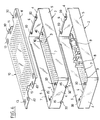
- FIG. 1 there is a tray of sterilization 1 according to the invention, which is arranged to support medical instrumentation.
- This tray consists of a tank 2, here rectangular in shape, consisting of a bottom 3 to which walls are connected vertical sides 4 and 5.
- the bottom 3 conventionally presents perforations to allow cleaning correct as part of a decontamination and conventional sterilization.
- This bottom 3 is equipped with different inserts 8, generally of plastic material such as teflon, which support instrumentation
- the illustration given here does not constitute naturally that an example, insofar as the instruments could be of very different types, and where the bac will contain a plurality of instruments, generally associated to a particular type of surgery.
- At the side walls 4 corresponding to the width of the tank there are two dishes 6 facing the inside which form two handles.
- the cover 10 also having perforations for the same reason as that previously given, generally includes a schematic drawing 12 which makes it possible to identify immediately from the outside, when the sterilization tray is closed by its cover, the instruments that are contained in the bac. Drawing 12 also facilitates repositioning instruments, after use, in the tray Finished.
- the cover 10 also has below two longitudinal wings 11, which facilitate the setting in place the cover 10 on the tray 2, like a sliding drawer.
- each handle plate 6 is equipped at least one attachment stud 20 consisting of a foot at least partly made of flexible material and by a larger head above said foot.
- attachment stud 20 consisting of a foot at least partly made of flexible material and by a larger head above said foot.
- the foot of the attachment stud 20 consists of a rigid baluster 21 surrounded on its entire height by a sleeve 22 made of flexible material, by silicone example.
- the enlarged head 23 of the attachment stud 20 is here in one piece with the baluster 21, in thus forming a shoulder piece, with a central thread 24 for fixing said stud on the flat concerned 6 to by means of a screw 25.
- This sleeve or ring 22 made of material flexible is susceptible to radial deformation during the attachment of the cover 10 at the lights associated outlets.
- the cover 10 has indeed at one end at least one through light 30 of a first type with an intermediate constriction 31 forming a hard point passage for the foot of the attachment stud 20 concerned, and at its opposite end at least one non-emerging light 40 of a second type having a keyhole shape whose wide part allows the passage of the head of the attachment stud concerned and the narrow part the sliding of said stud.
- the presence of intermediate tightening 31 forming passage to hard point is extremely advantageous insofar as it allows to achieve effective locking with sensation specifies to the operator that the locking position, with stop at the bottom of the lights concerned, is good reached.
- the light emerging from the first type 30 has an intermediate constriction 31 which is interposed between an entry portion 32 whose width decreases towards said constriction and a bottom portion 33 substantially circular.
- This input part 32 constitutes thus a guide corridor for the base of the stud attachment 20.
- the presence of the longitudinal wings 11 on the cover of recovery 10 already plays a major role in guiding the longitudinal direction during installation and lid lock.
- the foot of the attachment stud is received in the substantially circular bottom portion 33, the diameter of which will therefore be close to that of said foot.
- the inlet part 32 is defined by two straight sections inclined towards each other, connecting to two parallel straight sections that form the tightening intermediate 31.
- the non-emerging light of the second type 40 has a shape which was already used in known sterilization trays, but the dimensioning of the latter is however chosen in relation to the particular structure of the hanging studs whose foot is at least in part made of flexible material.
- the non-emerging light of the second type 40 thus has a wide part 41 of circular shape, the diameter of which is sufficient to allow the passage of the head 23 of the latching block concerned 20, and a narrow part 42 forming oblong light with parallel edges and with a semi-circular bottom, the width c of which is constant and substantially equal to the outside diameter of the base of said stud.
- the head 23 of the two studs 20 associated with the lights 40 are passed through the associated wide part 41, the other two studs being then arranged at the entry portion 32 of opening lights of the first type 30.
- the feet of the hanging pins After sliding of the cover 10, which is supported on the wings 7 and the dishes 6 of tray 2, the feet of the hanging pins thus arrive respectively at the bottom of the narrow part 42 for non-emerging lights of the second type 40, and in the bottom part 33 for the through lights of the first type 30.
- a width c of 9.5 millimeters can be chosen for the narrow part 42 of the non-emerging light 40, then, for the through light 30, an intermediate constriction whose width a is 9 millimeters, and a circular bottom portion 33 with a diameter b of 10 millimeters.
- each dish 6 of tray 2 is equipped two attachment pads 20, the four pads of said tray being identical and positioned in a rectangle.
- the cover 10 has at one end a pair of lights of the first type 30, and at the other end a pair of lights of the second type 40, these four lights being positioned in a rectangle.
- half-bins and / or half-covers it is however possible to provide for a more elaborate modular design, with half-bins and / or half-covers.
- half a tray or a half-lid will only present one pawn respectively hanging at each end or a light of each type at each end.
- FIG. 6 thus illustrates such a possibility, and we see that the upper tray, which is inserted between the lower tank and the cover 10, has a bottom 3 which is fitted with lights from the first and of the second types which are identical to those of the cover 10 already described, to allow a connection with the other underlying sterilization tray by the attachment studs 20 of the latter.
- Such an arrangement of sterilization tray will be better understood by referring in Figures 7 to 9.
- the second type 30 emerging lights provided on the bottom 3 of the tank is connected to a notch 35 formed in the adjacent side wall 4 of said tank, said notch having a height at least equal to that of hooking pins 20 to allow installation from one tray to the other by sliding.
- the locking means is consisting of a movable bar 50 which is secured at the bottom of the tank 3 by two screws 52 whose rods pass in an oblong lumen 53 of said bottom 3.
- the bar 50 has a main securing part 51 surmounted by an operating part 55, and a spoiler 54 which comes, in the locked position, to be inserted between the attachment pin 20 of the lower plate, and the wall lateral 4 of the upper plate.
- the movable bar 50 can thus slide between a release position ( Figure 10a) in which the latch pin 20 of the underlying plate can penetrate or leave the through light 30, and a locking position (Figure 10b) in which said hooking pin is blocked in said lumen emerging.
- compartment 103 corresponds to all of the space available inside the container 100, but it goes without saying that we can plan mixed housing, with space 103 which does not constitute only part of this space, the rest being dedicated to the implantation of other instruments, as well as it is known to foresee it.
- Trays 1, here at number three, are made as described above, being locked to each other, to form a unitary set of three stacked trays covered above with a cover 10.
- the compartment 103 has a dimensioning which corresponds to the size of the sterilization trays 1, which allows both to respect the usual rules in sterilization material (for example with the place a textile envelope around the stack of trays), and to avoid any risk of separation of one of the trays during a somewhat brutal transport.
Landscapes
- Health & Medical Sciences (AREA)
- Life Sciences & Earth Sciences (AREA)
- Animal Behavior & Ethology (AREA)
- Surgery (AREA)
- General Health & Medical Sciences (AREA)
- Public Health (AREA)
- Veterinary Medicine (AREA)
- Engineering & Computer Science (AREA)
- Biomedical Technology (AREA)
- Heart & Thoracic Surgery (AREA)
- Medical Informatics (AREA)
- Molecular Biology (AREA)
- Nuclear Medicine, Radiotherapy & Molecular Imaging (AREA)
- Epidemiology (AREA)
- Apparatus For Disinfection Or Sterilisation (AREA)
Applications Claiming Priority (2)
| Application Number | Priority Date | Filing Date | Title |
|---|---|---|---|
| FR9906071 | 1999-05-12 | ||
| FR9906071A FR2793416B1 (fr) | 1999-05-12 | 1999-05-12 | Plateau de sterilisation et conteneur associe de plateaux superposes |
Publications (1)
| Publication Number | Publication Date |
|---|---|
| EP1051981A1 true EP1051981A1 (de) | 2000-11-15 |
Family
ID=9545532
Family Applications (1)
| Application Number | Title | Priority Date | Filing Date |
|---|---|---|---|
| EP00401259A Withdrawn EP1051981A1 (de) | 1999-05-12 | 2000-05-09 | Stapelbare Trägerplatten für Sterilisierungen und Behälter dafür |
Country Status (2)
| Country | Link |
|---|---|
| EP (1) | EP1051981A1 (de) |
| FR (1) | FR2793416B1 (de) |
Cited By (5)
| Publication number | Priority date | Publication date | Assignee | Title |
|---|---|---|---|---|
| EP2556757A1 (de) * | 2011-08-09 | 2013-02-13 | Multivac Sepp Haggenmüller GmbH & Co. KG | Behälter zur Aufnahme von Produkten während einer Hochdruckbehandlung |
| WO2015010124A1 (en) * | 2013-07-19 | 2015-01-22 | Summit Medical, Inc. | Corner protector for instrument sterilization tray |
| US9055755B2 (en) | 2011-08-09 | 2015-06-16 | Multivac Sepp Haggenmueller Gmbh & Co. Kg | Container for accommodating products during a high-pressure treatment |
| CN106620777A (zh) * | 2016-12-21 | 2017-05-10 | 明博医药技术开发(上海)有限公司 | 一种离心管灭菌盒 |
| WO2019227510A1 (zh) * | 2018-06-02 | 2019-12-05 | Zhu Xiuqing | 一种医疗器械用磁力消毒箱 |
Families Citing this family (1)
| Publication number | Priority date | Publication date | Assignee | Title |
|---|---|---|---|---|
| FR3028408A1 (fr) | 2014-11-13 | 2016-05-20 | Analytic- Tracabilite Hospitaliere | Tracabilite et suivi d'une boite de sterilisation et de son contenu |
Citations (4)
| Publication number | Priority date | Publication date | Assignee | Title |
|---|---|---|---|---|
| US5281400A (en) * | 1992-09-30 | 1994-01-25 | Carr Metal Products | Plastic autoclave tray and lid combination |
| US5340551A (en) * | 1992-11-25 | 1994-08-23 | C/T Med-Systems Ltd., Inc. | Dental cassette kit |
| US5384103A (en) * | 1992-03-17 | 1995-01-24 | Micromedics, Inc. | Instrument tray |
| US5628970A (en) * | 1995-09-26 | 1997-05-13 | Healthmark Industries, Co. | Sterilization tray assembly composed of a mineral filled polypropylene |
-
1999
- 1999-05-12 FR FR9906071A patent/FR2793416B1/fr not_active Expired - Lifetime
-
2000
- 2000-05-09 EP EP00401259A patent/EP1051981A1/de not_active Withdrawn
Patent Citations (4)
| Publication number | Priority date | Publication date | Assignee | Title |
|---|---|---|---|---|
| US5384103A (en) * | 1992-03-17 | 1995-01-24 | Micromedics, Inc. | Instrument tray |
| US5281400A (en) * | 1992-09-30 | 1994-01-25 | Carr Metal Products | Plastic autoclave tray and lid combination |
| US5340551A (en) * | 1992-11-25 | 1994-08-23 | C/T Med-Systems Ltd., Inc. | Dental cassette kit |
| US5628970A (en) * | 1995-09-26 | 1997-05-13 | Healthmark Industries, Co. | Sterilization tray assembly composed of a mineral filled polypropylene |
Cited By (6)
| Publication number | Priority date | Publication date | Assignee | Title |
|---|---|---|---|---|
| EP2556757A1 (de) * | 2011-08-09 | 2013-02-13 | Multivac Sepp Haggenmüller GmbH & Co. KG | Behälter zur Aufnahme von Produkten während einer Hochdruckbehandlung |
| US9055755B2 (en) | 2011-08-09 | 2015-06-16 | Multivac Sepp Haggenmueller Gmbh & Co. Kg | Container for accommodating products during a high-pressure treatment |
| WO2015010124A1 (en) * | 2013-07-19 | 2015-01-22 | Summit Medical, Inc. | Corner protector for instrument sterilization tray |
| US9119611B2 (en) | 2013-07-19 | 2015-09-01 | Summit Medical, Inc. | Corner protector for instrument sterilization tray |
| CN106620777A (zh) * | 2016-12-21 | 2017-05-10 | 明博医药技术开发(上海)有限公司 | 一种离心管灭菌盒 |
| WO2019227510A1 (zh) * | 2018-06-02 | 2019-12-05 | Zhu Xiuqing | 一种医疗器械用磁力消毒箱 |
Also Published As
| Publication number | Publication date |
|---|---|
| FR2793416B1 (fr) | 2003-05-02 |
| FR2793416A1 (fr) | 2000-11-17 |
Similar Documents
| Publication | Publication Date | Title |
|---|---|---|
| BE1005930A3 (fr) | Necesaire pour boite a casse-croute. | |
| BE1005010A3 (fr) | Assemblage de fermeture avec couvercle articule. | |
| FR2476329A1 (fr) | Boitier pour vues de meme format | |
| CH634973A5 (fr) | Boite a dejeuner pour enfants. | |
| FR2498357A1 (fr) | Coffret de rangement d'organes de memoire magnetique | |
| FR2771390A1 (fr) | Plateau pour le groupage d'objets | |
| FR2818243A1 (fr) | Ensemble de boites modulaires pour lames porte-objets de microscope, et boite modulaire destinee a former un tel ensemble empile | |
| FR2802074A1 (fr) | Dispositif de prehension pour ustensile de cuisson | |
| EP3785583B1 (de) | Heissluftkochgerät mit mehreren funktionseinstellungen | |
| EP1051981A1 (de) | Stapelbare Trägerplatten für Sterilisierungen und Behälter dafür | |
| EP2102074B1 (de) | Schutzkasten zum transport oder zur lagerung eines teils in der form einer platte mit einer öffnung | |
| FR2589698A1 (fr) | Table a rallonges | |
| FR3069143A1 (fr) | Un plateau support d'un outil pour appareil de preparation culinaire et appareil de preparation culinaire le comportant | |
| EP0124446B1 (de) | Werkzeugkoffer | |
| FR2693101A1 (fr) | Plateau et plateau-cassette modulaire pour la procédure dentaire opératoire et le recyclage de l'instrumentation. | |
| EP0634344A1 (de) | Doppelkammer-Behälter zum Sammeln von Abfällen, insbesondere Hausmüll | |
| EP1443008A1 (de) | Vorrichtung zum Aufnehmen von Briefumschlägen | |
| EP0802759B2 (de) | Kochgeschirr mit einem griff und mitteln zum halten eines geräts | |
| EP4027941A1 (de) | Vorrichtung zum handhaben von mehreren halmen zum verpacken von tiersamen | |
| LU87906A1 (fr) | Boite a outils et ensemble de bacs | |
| EP1658799B1 (de) | Reibe | |
| FR2624101A1 (fr) | Coffret en matiere synthetique moulee pour objets plats et minces | |
| FR2719821A1 (fr) | Bac pliant en matière plastique. | |
| EP2017199A1 (de) | Verpackungsvorrichtung für biologische Produkte | |
| FR2758074A1 (fr) | Dispositif de prehension pour ustensile de cuisson |
Legal Events
| Date | Code | Title | Description |
|---|---|---|---|
| PUAI | Public reference made under article 153(3) epc to a published international application that has entered the european phase |
Free format text: ORIGINAL CODE: 0009012 |
|
| AK | Designated contracting states |
Kind code of ref document: A1 Designated state(s): DE FR GB |
|
| AX | Request for extension of the european patent |
Free format text: AL;LT;LV;MK;RO;SI |
|
| 17P | Request for examination filed |
Effective date: 20010323 |
|
| AKX | Designation fees paid |
Free format text: DE FR GB |
|
| GRAP | Despatch of communication of intention to grant a patent |
Free format text: ORIGINAL CODE: EPIDOSNIGR1 |
|
| STAA | Information on the status of an ep patent application or granted ep patent |
Free format text: STATUS: THE APPLICATION IS DEEMED TO BE WITHDRAWN |
|
| 18D | Application deemed to be withdrawn |
Effective date: 20050120 |