EP1051981A1 - Stackable sterilisation trays and containers provided with them - Google Patents
Stackable sterilisation trays and containers provided with them Download PDFInfo
- Publication number
- EP1051981A1 EP1051981A1 EP00401259A EP00401259A EP1051981A1 EP 1051981 A1 EP1051981 A1 EP 1051981A1 EP 00401259 A EP00401259 A EP 00401259A EP 00401259 A EP00401259 A EP 00401259A EP 1051981 A1 EP1051981 A1 EP 1051981A1
- Authority
- EP
- European Patent Office
- Prior art keywords
- lights
- sterilization
- type
- cover
- sterilization tray
- Prior art date
- Legal status (The legal status is an assumption and is not a legal conclusion. Google has not performed a legal analysis and makes no representation as to the accuracy of the status listed.)
- Withdrawn
Links
Images


Classifications
-
- A—HUMAN NECESSITIES
- A61—MEDICAL OR VETERINARY SCIENCE; HYGIENE
- A61L—METHODS OR APPARATUS FOR STERILISING MATERIALS OR OBJECTS IN GENERAL; DISINFECTION, STERILISATION OR DEODORISATION OF AIR; CHEMICAL ASPECTS OF BANDAGES, DRESSINGS, ABSORBENT PADS OR SURGICAL ARTICLES; MATERIALS FOR BANDAGES, DRESSINGS, ABSORBENT PADS OR SURGICAL ARTICLES
- A61L2/00—Disinfection or sterilisation of materials or objects, in general; Accessories therefor
- A61L2/26—Accessories
-
- A—HUMAN NECESSITIES
- A61—MEDICAL OR VETERINARY SCIENCE; HYGIENE
- A61B—DIAGNOSIS; SURGERY; IDENTIFICATION
- A61B50/00—Containers, covers, furniture or holders specially adapted for surgical or diagnostic appliances or instruments, e.g. sterile covers
- A61B50/30—Containers specially adapted for packaging, protecting, dispensing, collecting or disposing of surgical or diagnostic appliances or instruments
- A61B50/33—Trays
-
- A—HUMAN NECESSITIES
- A61—MEDICAL OR VETERINARY SCIENCE; HYGIENE
- A61L—METHODS OR APPARATUS FOR STERILISING MATERIALS OR OBJECTS IN GENERAL; DISINFECTION, STERILISATION OR DEODORISATION OF AIR; CHEMICAL ASPECTS OF BANDAGES, DRESSINGS, ABSORBENT PADS OR SURGICAL ARTICLES; MATERIALS FOR BANDAGES, DRESSINGS, ABSORBENT PADS OR SURGICAL ARTICLES
- A61L2103/00—Materials or objects being the target of disinfection or sterilisation
- A61L2103/15—Laboratory, medical or dentistry appliances, e.g. catheters or sharps
Definitions
- the present invention relates to the field of medical equipment, especially trays sterilization equipment fitted to support instrumentation medical.
- Such trays are commonly used by surgeons or associated assistants to transport on the operating site medical instrumentation in related to the intervention concerned.
- the tray is arranged to support various instruments, for example clamps, endoscopes etc. which are more or less fragile.
- These trays must be made to be able endure, after use, the usual phases of cleaning, in accordance with a decontamination and sterilization as is the practice in the medical field.
- the invention relates more particularly to a sterilization tray fitted to support a medical instrumentation, consisting of a tank with upper two plates forming handles, said plates being surmounted by projecting studs used to hang a covering cover fitted for this purpose with associated lights, in accordance with the preamble to the claim 1.
- the rigid studs are made in the form of metal nipples riveted or screwed onto the plates forming handles, so that even with precise machining of cover lights, one cannot achieve a hold truly reliable cover in the hooked position of it.
- These sterilization trays can be possibly superimposed, so that they comprise usually centering pads so as to be stackable in a stack which can be arranged at inside a container. It has thus been proposed containers with a compartment for three stacked trays.
- the compartment is usually dimensioned so that the three trays are exactly received inside the compartment, without risk for detaching a tray or lid closing the upper shelf.
- the container is opened, when the operator clears the upper tray, it may be that by an awkward movement a shock is exerted on the cover and slide it over the relevant container and do not more protects the inside of the tray.
- the object of the invention is to improve the structure such sterilization trays to avoid aforementioned drawbacks.
- the object of the invention is therefore to design a sterilization tray whose structure allows both reliable locking of its cover, while allowing combinations of overlays of various types, with also the possibility of locking between them the superimposed trays.
- each handle plate is equipped with at least a hanging stud constituted by a foot at least in part made of flexible material and by a head more wide above said foot, and in which the cover additionally has at least one light at one end opening of a first type presenting a constriction intermediate forming a hard point passage for the foot of the relevant attachment stud, and at its opposite end at least one non-emerging light of a second type having the shape of a keyhole, the part of which wide allows the passage of the head of the attachment stud concerned and the narrow part the sliding of the foot of said stud, in accordance with the characterizing part of the claim 1.
- the foot of each attachment stud is formed by a rigid baluster surrounded over its entire height a sleeve made of flexible material, for example silicone, and the enlarged head of the attachment stud is one piece with the baluster, with a central thread for the fixing of said stud on the dish concerned.
- This mode of construction allows the sleeve to be replaced if necessary in flexible material in the event of premature wear thereof, while retaining the basic metallic structure constituting the attachment studs.
- each dish of the tray is equipped of two attachment pads, the four pads of said tray being identical and positioned in a rectangle.
- the or each light opening of the first type has an intermediate tightening which is sandwiched between an input part whose the width decreases towards said constriction and a substantially circular bottom part.
- the entrance part is defined by two straight sections inclined towards each other, connecting to two parallel straight sections that form the tightening intermediate.
- the passage width of the intermediate tightening is significantly less than outside diameter of the foot of the attachment stud concerned, and the diameter of the bottom part is substantially equal said outside diameter.
- the or each light non-opening of the second type has a wide part circular whose diameter is sufficient for the passage of the head of the attachment block concerned, and a part narrow whose width is constant and appreciably equal to the outside diameter of the base of said stud.
- the cover has a pair of lights at one end of the first type and at the other end a pair of lights of the second type, these four lights being positioned in a rectangle.
- the bin has a bottom which is equipped with lights of the first and second types, identical to those of the cover, to allow a fastening with another underlying sterilization tray by the latter's attachment studs. This allows stack stacks of sterilization trays superimposed perfectly joined together.
- the opening light or lights of the second type provided on the bottom of the tank connect to a notch in the side wall adjacent to said tank, said notch having a height at less equal to that of the hanging pins to allow placement by sliding from one tray to the other.
- the studs of the dishes and the lights from the bottom are respectively plumb with each other. This ensures the verticality of the stack of stacked sterilization trays.
- the bin is equipped with a means of locking at least one of the lights outlets of the second type provided on the bottom of said bac.
- the said locking means is constituted by a movable bar secured to the tray and sliding between a release position in which the latching pin of the underlying shelf can enter or exit the through light, and a locking position in which said attachment pin is blocked in said emerging light.
- the structure exposed above of the sterilization and lid is perfectly compatible with a modular design with half components.
- the sterilization tray is arranged in the form of a semi-overhanging tray a tray and attached to it, the cover by means of at least a half-cover or a cover hung by the relevant hanging studs.
- the invention also relates to a container for sterilization, of the type comprising a compartment intended to receive a plurality of sterilization trays superimposed, whose upper plate is covered by a cover, said container being remarkable in that the trays have at least one of the characteristics above, and that the compartment has a dimension which corresponds to the size of said plates.
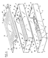
- FIG. 1 there is a tray of sterilization 1 according to the invention, which is arranged to support medical instrumentation.
- This tray consists of a tank 2, here rectangular in shape, consisting of a bottom 3 to which walls are connected vertical sides 4 and 5.
- the bottom 3 conventionally presents perforations to allow cleaning correct as part of a decontamination and conventional sterilization.
- This bottom 3 is equipped with different inserts 8, generally of plastic material such as teflon, which support instrumentation
- the illustration given here does not constitute naturally that an example, insofar as the instruments could be of very different types, and where the bac will contain a plurality of instruments, generally associated to a particular type of surgery.
- At the side walls 4 corresponding to the width of the tank there are two dishes 6 facing the inside which form two handles.
- the cover 10 also having perforations for the same reason as that previously given, generally includes a schematic drawing 12 which makes it possible to identify immediately from the outside, when the sterilization tray is closed by its cover, the instruments that are contained in the bac. Drawing 12 also facilitates repositioning instruments, after use, in the tray Finished.
- the cover 10 also has below two longitudinal wings 11, which facilitate the setting in place the cover 10 on the tray 2, like a sliding drawer.
- each handle plate 6 is equipped at least one attachment stud 20 consisting of a foot at least partly made of flexible material and by a larger head above said foot.
- attachment stud 20 consisting of a foot at least partly made of flexible material and by a larger head above said foot.
- the foot of the attachment stud 20 consists of a rigid baluster 21 surrounded on its entire height by a sleeve 22 made of flexible material, by silicone example.
- the enlarged head 23 of the attachment stud 20 is here in one piece with the baluster 21, in thus forming a shoulder piece, with a central thread 24 for fixing said stud on the flat concerned 6 to by means of a screw 25.
- This sleeve or ring 22 made of material flexible is susceptible to radial deformation during the attachment of the cover 10 at the lights associated outlets.
- the cover 10 has indeed at one end at least one through light 30 of a first type with an intermediate constriction 31 forming a hard point passage for the foot of the attachment stud 20 concerned, and at its opposite end at least one non-emerging light 40 of a second type having a keyhole shape whose wide part allows the passage of the head of the attachment stud concerned and the narrow part the sliding of said stud.
- the presence of intermediate tightening 31 forming passage to hard point is extremely advantageous insofar as it allows to achieve effective locking with sensation specifies to the operator that the locking position, with stop at the bottom of the lights concerned, is good reached.
- the light emerging from the first type 30 has an intermediate constriction 31 which is interposed between an entry portion 32 whose width decreases towards said constriction and a bottom portion 33 substantially circular.
- This input part 32 constitutes thus a guide corridor for the base of the stud attachment 20.
- the presence of the longitudinal wings 11 on the cover of recovery 10 already plays a major role in guiding the longitudinal direction during installation and lid lock.
- the foot of the attachment stud is received in the substantially circular bottom portion 33, the diameter of which will therefore be close to that of said foot.
- the inlet part 32 is defined by two straight sections inclined towards each other, connecting to two parallel straight sections that form the tightening intermediate 31.
- the non-emerging light of the second type 40 has a shape which was already used in known sterilization trays, but the dimensioning of the latter is however chosen in relation to the particular structure of the hanging studs whose foot is at least in part made of flexible material.
- the non-emerging light of the second type 40 thus has a wide part 41 of circular shape, the diameter of which is sufficient to allow the passage of the head 23 of the latching block concerned 20, and a narrow part 42 forming oblong light with parallel edges and with a semi-circular bottom, the width c of which is constant and substantially equal to the outside diameter of the base of said stud.
- the head 23 of the two studs 20 associated with the lights 40 are passed through the associated wide part 41, the other two studs being then arranged at the entry portion 32 of opening lights of the first type 30.
- the feet of the hanging pins After sliding of the cover 10, which is supported on the wings 7 and the dishes 6 of tray 2, the feet of the hanging pins thus arrive respectively at the bottom of the narrow part 42 for non-emerging lights of the second type 40, and in the bottom part 33 for the through lights of the first type 30.
- a width c of 9.5 millimeters can be chosen for the narrow part 42 of the non-emerging light 40, then, for the through light 30, an intermediate constriction whose width a is 9 millimeters, and a circular bottom portion 33 with a diameter b of 10 millimeters.
- each dish 6 of tray 2 is equipped two attachment pads 20, the four pads of said tray being identical and positioned in a rectangle.
- the cover 10 has at one end a pair of lights of the first type 30, and at the other end a pair of lights of the second type 40, these four lights being positioned in a rectangle.
- half-bins and / or half-covers it is however possible to provide for a more elaborate modular design, with half-bins and / or half-covers.
- half a tray or a half-lid will only present one pawn respectively hanging at each end or a light of each type at each end.
- FIG. 6 thus illustrates such a possibility, and we see that the upper tray, which is inserted between the lower tank and the cover 10, has a bottom 3 which is fitted with lights from the first and of the second types which are identical to those of the cover 10 already described, to allow a connection with the other underlying sterilization tray by the attachment studs 20 of the latter.
- Such an arrangement of sterilization tray will be better understood by referring in Figures 7 to 9.
- the second type 30 emerging lights provided on the bottom 3 of the tank is connected to a notch 35 formed in the adjacent side wall 4 of said tank, said notch having a height at least equal to that of hooking pins 20 to allow installation from one tray to the other by sliding.
- the locking means is consisting of a movable bar 50 which is secured at the bottom of the tank 3 by two screws 52 whose rods pass in an oblong lumen 53 of said bottom 3.
- the bar 50 has a main securing part 51 surmounted by an operating part 55, and a spoiler 54 which comes, in the locked position, to be inserted between the attachment pin 20 of the lower plate, and the wall lateral 4 of the upper plate.
- the movable bar 50 can thus slide between a release position ( Figure 10a) in which the latch pin 20 of the underlying plate can penetrate or leave the through light 30, and a locking position (Figure 10b) in which said hooking pin is blocked in said lumen emerging.
- compartment 103 corresponds to all of the space available inside the container 100, but it goes without saying that we can plan mixed housing, with space 103 which does not constitute only part of this space, the rest being dedicated to the implantation of other instruments, as well as it is known to foresee it.
- Trays 1, here at number three, are made as described above, being locked to each other, to form a unitary set of three stacked trays covered above with a cover 10.
- the compartment 103 has a dimensioning which corresponds to the size of the sterilization trays 1, which allows both to respect the usual rules in sterilization material (for example with the place a textile envelope around the stack of trays), and to avoid any risk of separation of one of the trays during a somewhat brutal transport.
Landscapes
- Health & Medical Sciences (AREA)
- Life Sciences & Earth Sciences (AREA)
- Veterinary Medicine (AREA)
- Animal Behavior & Ethology (AREA)
- General Health & Medical Sciences (AREA)
- Public Health (AREA)
- Surgery (AREA)
- Epidemiology (AREA)
- Nuclear Medicine, Radiotherapy & Molecular Imaging (AREA)
- Engineering & Computer Science (AREA)
- Biomedical Technology (AREA)
- Heart & Thoracic Surgery (AREA)
- Medical Informatics (AREA)
- Molecular Biology (AREA)
- Apparatus For Disinfection Or Sterilisation (AREA)
Abstract
L'invention concerne un plateau de stérilisation (1) aménagé pour supporter une instrumentation médicale, constitué par un bac (2) présentant supérieurement deux plats (6) formant poignées qui sont surmontés de plots d'accrochage (20). Conformément à l'invention, chaque plot d'accrochage (20) est constitué par un pied au moins en partie réalisé en matériau souple et par une tête plus large surmontant ledit pied. Des lumières débouchantes (30) d'un premier type, présentant un resserrement (31) intermédiaire formant un passage à point dur, et des lumières non débouchantes (40) d'un deuxième type présentant une forme de trou de serrure, sont prévus sur le couvercle de recouvrement (10), et de préférence aussi sur le fond (3) du bac (2) pour permettre une solidarisation entre plateaux superposés. <IMAGE>The invention relates to a sterilization tray (1) arranged to support medical instrumentation, consisting of a tray (2) having two upper plates (6) forming handles which are surmounted by hooking studs (20). According to the invention, each attachment stud (20) is constituted by a foot at least partially made of flexible material and by a larger head surmounting said foot. Openings (30) of a first type, having an intermediate constriction (31) forming a hard point passage, and non-opening lights (40) of a second type having a keyhole shape, are provided on the cover cover (10), and preferably also on the bottom (3) of the tank (2) to allow a connection between superimposed trays. <IMAGE>
Description
La présente invention concerne le domaine de l'équipement médical, et plus particulièrement les plateaux de stérilisation aménagés pour supporter une instrumentation médicale.The present invention relates to the field of medical equipment, especially trays sterilization equipment fitted to support instrumentation medical.
Pour l'arrière-plan technologique de l'invention, on pourra se référer aux documents US-A-5 340 551, US-A-5 281 400, US-A-5 384 103 et US-A-5 628 970.For the technological background of the invention, we can refer to documents US-A-5 340 551, US-A-5 281,400, US-A-5,384,103 and US-A-5,628,970.
De tels plateaux sont couramment utilisés par les chirurgiens ou les personnels d'aide associés pour transporter sur le site opératoire l'instrumentation médicale en rapport avec l'intervention concernée. Le plateau est aménagé pour supporter divers instruments, par exemple des pinces, des endoscopes etc. qui sont plus ou moins fragiles. Ces plateaux doivent être réalisés pour pouvoir supporter, après utilisation, les phases habituelles de nettoyage, conformément à un cycle de décontamination et de stérilisation comme c'est l'usage dans le domaine médical.Such trays are commonly used by surgeons or associated assistants to transport on the operating site medical instrumentation in related to the intervention concerned. The tray is arranged to support various instruments, for example clamps, endoscopes etc. which are more or less fragile. These trays must be made to be able endure, after use, the usual phases of cleaning, in accordance with a decontamination and sterilization as is the practice in the medical field.
L'invention concerne plus particulièrement un plateau de stérilisation aménagé pour supporter une instrumentation médicale, constitué par un bac présentant supérieurement deux plats formant poignées, lesdits plats étant surmontés par des plots en saillie servant à accrocher un couvercle de recouvrement muni à cet effet de lumières associées, conformément au préambule de la revendication 1.The invention relates more particularly to a sterilization tray fitted to support a medical instrumentation, consisting of a tank with upper two plates forming handles, said plates being surmounted by projecting studs used to hang a covering cover fitted for this purpose with associated lights, in accordance with the preamble to the claim 1.
On rencontre ainsi souvent des couvercles plats de forme rectangulaire, à une extrémité desquels on trouve une paire de lumières débouchantes en forme de U, et au voisinage de l'autre extrémité des lumières en forme de trou de serrure. Les deux plats formant poignées sont surmontés par des plots rigides dont la tête élargie permet un accrochage du couvercle au niveau des lumières précitées. Pour le verrouillage, le couvercle de recouvrement est posé sur le dessus du bac, puis glissé longitudinalement de façon que les plots rigides coulissent dans les lumières associées, et en particulier réalisent l'accrochage du couvercle après une course de translation déterminée.We often meet flat lids rectangular in shape, at one end of which a pair of U-shaped through lights, and at vicinity of the other end of the shaped lights keyhole. The two dishes forming handles are surmounted by rigid studs whose enlarged head allows a hooking of the cover at the level of the lights mentioned above. For locking, the cover cover is placed on top of the tank, then slid longitudinally so that the rigid studs slide in the associated lights, and in particular realize the attachment of the cover after a travel of translation determined.
Les plots rigides sont réalisés sous forme de tétons métalliques rivetés ou vissés sur les plats formant poignées, de sorte que même avec un usinage précis des lumières du couvercle, on ne peut parvenir à un maintien véritablement fiable du couvercle dans la position accrochée de celui-ci.The rigid studs are made in the form of metal nipples riveted or screwed onto the plates forming handles, so that even with precise machining of cover lights, one cannot achieve a hold truly reliable cover in the hooked position of it.
Ces plateaux de stérilisation peuvent être éventuellement superposés, de sorte qu'ils comportent habituellement des pastilles de centrage de façon à être gerbables selon un empilement qui peut être disposé à l'intérieur d'un conteneur. Il a ainsi été proposé des conteneurs présentant un compartiment recevant trois plateaux superposés. Le compartiment est habituellement dimensionné de telle façon que les trois plateaux soient exactement reçus à l'intérieur du compartiment, sans risque de désolidarisation d'un plateau ou du couvercle fermant le plateau supérieur. Néanmoins, à l'ouverture du conteneur, lorsque l'opérateur dégage le plateau supérieur, il se peut que par un mouvement maladroit un choc soit exercé sur le couvercle et que celui-ci glisse sur le bac concerné et ne protège plus l'intérieur du plateau. En outre, il est fréquent que l'opérateur doive manipuler un empilement de plateaux sorti du conteneur, et il faut bien reconnaítre que l'absence de solidarisation entre les plateaux superposés induit un risque de glissement relatif et de chute d'un des plateaux, qui risque d'endommager l'instrumentation concernée, avec des conséquences qui peuvent être dramatiques pour le fonctionnement de ces instruments, sans parler du coût inhérent au remplacement de ceux-ci. Le léger centrage procuré par quatre pastilles agencées aux quatre coins du fond des bacs, venant s'insérer dans le contour du plateau inférieur, n'est donc aucunement satisfaisant en terme de verrouillage.These sterilization trays can be possibly superimposed, so that they comprise usually centering pads so as to be stackable in a stack which can be arranged at inside a container. It has thus been proposed containers with a compartment for three stacked trays. The compartment is usually dimensioned so that the three trays are exactly received inside the compartment, without risk for detaching a tray or lid closing the upper shelf. However, when the container is opened, when the operator clears the upper tray, it may be that by an awkward movement a shock is exerted on the cover and slide it over the relevant container and do not more protects the inside of the tray. In addition, it is frequent that the operator must handle a stack of trays out of the container, and we must recognize that the lack of connection between the superimposed trays induces a risk of relative slipping and falling of a trays, which may damage the instrumentation concerned, with consequences that can be dramatic for the operation of these instruments, not to mention the cost inherent in replacing them. The light centering provided by four pads arranged at the four corners of the bottom of the tanks, which fit into the outline of the lower plate, is therefore not at all satisfactory in lock term.
L'invention a pour objet d'améliorer la structure de tels plateaux de stérilisation afin d'éviter les inconvénients précités.The object of the invention is to improve the structure such sterilization trays to avoid aforementioned drawbacks.
L'invention a ainsi pour but de concevoir un plateau de stérilisation dont la structure permet à la fois un verrouillage fiable de son couvercle de recouvrement, tout en autorisant des combinaisons de superpositions de types variés, avec aussi la possibilité de verrouiller entre eux les plateaux superposés.The object of the invention is therefore to design a sterilization tray whose structure allows both reliable locking of its cover, while allowing combinations of overlays of various types, with also the possibility of locking between them the superimposed trays.
Ce problème est résolu conformément à l'invention grâce à un plateau de stérilisation du type précité, dans lequel chaque plat formant poignée est équipé d'au moins un plot d'accrochage constitué par un pied au moins en partie réalisé en matériau souple et par une tête plus large surmontant ledit pied, et dans lequel le couvercle présente en outre à une extrémité au moins une lumière débouchante d'un premier type présentant un resserrement intermédiaire formant un passage à point dur pour le pied du plot d'accrochage concerné, et à son extrémité opposée au moins une lumière non débouchante d'un deuxième type présentant une forme de trou de serrure dont la partie large permet le passage de la tête du plot d'accrochage concerné et la partie étroite le coulissement du pied dudit plot, conformément à la partie caractérisante de la revendication 1.This problem is solved in accordance with the invention thanks to a sterilization tray of the aforementioned type, in which each handle plate is equipped with at least a hanging stud constituted by a foot at least in part made of flexible material and by a head more wide above said foot, and in which the cover additionally has at least one light at one end opening of a first type presenting a constriction intermediate forming a hard point passage for the foot of the relevant attachment stud, and at its opposite end at least one non-emerging light of a second type having the shape of a keyhole, the part of which wide allows the passage of the head of the attachment stud concerned and the narrow part the sliding of the foot of said stud, in accordance with the characterizing part of the claim 1.
L'agencement de telles lumières débouchantes à resserrement intermédiaire permet de réaliser, en combinaison avec le caractère déformable du pied des plots d'accrochage, un verrouillage qui s'apparente tout à fait à un encliquetage, procurant une fiabilité optimale.The arrangement of such through lights at intermediate tightening makes it possible, in combination with the deformable nature of the base of the studs hooking, a lock that is very similar click-in, providing optimum reliability.
Conformément à un mode de réalisation particulier, le pied de chaque plot d'accrochage est constitué par une colonnette rigide entourée sur toute sa hauteur d'un manchon en matériau souple, par exemple en silicone, et la tête élargie du plot d'accrochage est d'une pièce avec la colonnette, avec un filetage central pour la fixation dudit plot sur le plat concerné. Ce mode de construction permet de remplacer si nécessaire le manchon en matériau souple en cas d'usure prématurée de celui-ci, tout en conservant la structure de base en général métallique constituant les plots d'accrochage.In accordance with a particular embodiment, the foot of each attachment stud is formed by a rigid baluster surrounded over its entire height a sleeve made of flexible material, for example silicone, and the enlarged head of the attachment stud is one piece with the baluster, with a central thread for the fixing of said stud on the dish concerned. This mode of construction allows the sleeve to be replaced if necessary in flexible material in the event of premature wear thereof, while retaining the basic metallic structure constituting the attachment studs.
Avantageusement, chaque plat du bac est équipé de deux plots d'accrochage, les quatre plots dudit bac étant identiques et positionnés selon un rectangle.Advantageously, each dish of the tray is equipped of two attachment pads, the four pads of said tray being identical and positioned in a rectangle.
De préférence encore, la ou chaque lumière débouchante du premier type a un resserrement intermédiaire qui est intercalé entre une partie d'entrée dont la largeur diminue en direction dudit resserrement et une partie de fond sensiblement circulaire. En particulier, la partie d'entrée est définie par deux tronçons rectilignes inclinés l'un vers l'autre, se raccordant à deux tronçons rectilignes parallèles qui forment le resserrement intermédiaire.More preferably, the or each light opening of the first type has an intermediate tightening which is sandwiched between an input part whose the width decreases towards said constriction and a substantially circular bottom part. In particular, the entrance part is defined by two straight sections inclined towards each other, connecting to two parallel straight sections that form the tightening intermediate.
De préférence alors, la largeur de passage du resserrement intermédiaire est notablement inférieure au diamètre extérieur du pied du plot d'accrochage concerné, et le diamètre de la partie de fond est sensiblement égal audit diamètre extérieur.Preferably then, the passage width of the intermediate tightening is significantly less than outside diameter of the foot of the attachment stud concerned, and the diameter of the bottom part is substantially equal said outside diameter.
Avantageusement encore, la ou chaque lumière non débouchante du deuxième type a une partie large circulaire dont le diamètre est suffisant pour le passage de la tête du plot d'accrochage concerné, et une partie étroite dont la largeur est constante et sensiblement égale au diamètre extérieur du pied dudit plot.Advantageously again, the or each light non-opening of the second type has a wide part circular whose diameter is sufficient for the passage of the head of the attachment block concerned, and a part narrow whose width is constant and appreciably equal to the outside diameter of the base of said stud.
Il est par ailleurs intéressant de prévoir que le couvercle présente à une extrémité une paire de lumières du premier type et à l'autre extrémité une paire de lumières du deuxième type, ces quatre lumières étant positionnées selon un rectangle. It is also interesting to predict that the cover has a pair of lights at one end of the first type and at the other end a pair of lights of the second type, these four lights being positioned in a rectangle.
Conformément à un mode de réalisation particulièrement avantageux, le bac a un fond qui est équipé de lumières du premier et du deuxième types, identiques à celles du couvercle, pour permettre une solidarisation avec un autre plateau de stérilisation sous-jacent par les plots d'accrochage de ce dernier. Ceci permet de réaliser des empilements de plateaux de stérilisation superposés parfaitement solidarisés entre eux.In accordance with a particularly embodiment advantageous, the bin has a bottom which is equipped with lights of the first and second types, identical to those of the cover, to allow a fastening with another underlying sterilization tray by the latter's attachment studs. This allows stack stacks of sterilization trays superimposed perfectly joined together.
Avantageusement alors, la ou les lumières débouchantes du deuxième type prévues sur le fond du bac se raccordent à une encoche ménagée dans la paroi latérale adjacente dudit bac, ladite encoche ayant une hauteur au moins égale à celle des pions d'accrochage pour permettre une mise en place par glissement d'un plateau sur l'autre. De préférence, les plots des plats et les lumières du fond sont respectivement à l'aplomb l'un de l'autre. Ceci permet d'assurer la verticalité de l'empilement de plateaux de stérilisation superposés.Advantageously then, the opening light or lights of the second type provided on the bottom of the tank connect to a notch in the side wall adjacent to said tank, said notch having a height at less equal to that of the hanging pins to allow placement by sliding from one tray to the other. Preferably, the studs of the dishes and the lights from the bottom are respectively plumb with each other. This ensures the verticality of the stack of stacked sterilization trays.
On peut imaginer que dans des cas extrêmes d'erreur de manipulation d'un opérateur, un choc imprimé au niveau du plateau inférieur de l'empilement transporté à la main risque de désolidariser ce dernier plateau du restant de la pile. Pour éviter un tel risque qui aurait les conséquences fâcheuses déjà mentionnées plus haut, il est alors prévu que le bac soit équipé d'un moyen de verrouillage au niveau de l'une au moins des lumières débouchantes du deuxième type prévues sur le fond dudit bac.One can imagine that in extreme cases operator handling error, a printed shock at the lower plate of the transported stack by hand risks detaching this last tray from the remaining from the stack. To avoid such a risk which would have the unfortunate consequences already mentioned above, it it is then expected that the bin is equipped with a means of locking at least one of the lights outlets of the second type provided on the bottom of said bac.
Dans un mode particulier de réalisation, le moyen de verrouillage précité est constitué par une barrette mobile assujettie au bac et coulissant entre une position de dégagement dans laquelle le pion d'accrochage du plateau sous-jacent peut pénétrer dans ou sortir de la lumière débouchante, et une position de verrouillage dans laquelle ledit pion d'accrochage est bloqué dans ladite lumière débouchante.In a particular embodiment, the said locking means is constituted by a movable bar secured to the tray and sliding between a release position in which the latching pin of the underlying shelf can enter or exit the through light, and a locking position in which said attachment pin is blocked in said emerging light.
La structure exposée plus haut du plateau de stérilisation et du couvercle est parfaitement compatible avec une réalisation modulaire avec des demi-composants.The structure exposed above of the sterilization and lid is perfectly compatible with a modular design with half components.
On pourra ainsi prévoir que le plateau de stérilisation est agencé sous forme d'un demi-plateau surplombant un plateau et accroché à celui-ci, le recouvrement se faisant par au moins un demi-couvercle ou un couvercle accroché par les plots d'accrochage concernés.We can thus provide that the sterilization tray is arranged in the form of a semi-overhanging tray a tray and attached to it, the cover by means of at least a half-cover or a cover hung by the relevant hanging studs.
L'invention concerne également un conteneur de stérilisation, du type comportant un compartiment destiné à recevoir une pluralité de plateaux de stérilisation superposés, dont le plateau supérieur est recouvert par un couvercle, ledit conteneur étant remarquable en ce que les plateaux présentent l'une au moins des caractéristiques précitées, et que le compartiment a un dimensionnement qui correspond à l'encombrement desdits plateaux.The invention also relates to a container for sterilization, of the type comprising a compartment intended to receive a plurality of sterilization trays superimposed, whose upper plate is covered by a cover, said container being remarkable in that the trays have at least one of the characteristics above, and that the compartment has a dimension which corresponds to the size of said plates.
D'autres caractéristiques et avantages de l'invention apparaítront à la lumière de la description qui va suivre et des dessins annexés, concernant un mode de réalisation particulier, en référence aux figures où :
- la figure 1 est une vue en perspective éclatée illustrant un plateau de stérilisation conforme à l'invention, avec un bac surmonté de son couvercle de recouvrement;
- la figure 2 est une vue en coupe selon le plan II de la figure 1, montrant un détail à plus grande échelle au niveau de l'axe d'un des plots d'accrochage équipant les plats du bac ;
- la figure 3 est une vue de dessous du couvercle de recouvrement précité, et les figures 4 et 5 illustrent en coupe, à plus grande échelle, les détails IV et V correspondant respectivement à une lumière débouchante du premier type ( à resserrement intermédiaire) et une lumière non débouchante du deuxième type (en forme de trou de serrure) ;
- la figure 6 est une vue en perspective éclatée illustrant la superposition de deux plateaux de stérilisation, avec un verrouillage mutuel entre les deux bacs superposés grâce aux lumières du premier et du deuxième types également prévues sur le fond du bac supérieur ;
- la figure 7 est une vue de dessus de ce dernier bac, dont le fond est équipé des lumières spéciales de verrouillage ;
- les figures 8 et 9 sont des coupes de détail à plus grande échelle selon VIII-VIII et IX-IX de la figure 7, le plan de coupe passant par l'axe des plots d'accrochage ;
- les figures 10a et 10b sont des vues partielles d'une variante du plateau de stérilisation précédent, à fond équipé de lumières, avec un moyen supplémentaire de verrouillage au niveau de l'une au moins des lumières débouchantes, respectivement en position de déverrouillage et de verrouillage ;
- la figure 11 est une vue en coupe illustrant un conteneur de stérilisation conforme à l'invention, ici équipé de trois plateaux superposés, dont le plateau supérieur est fermé par un couvercle de recouvrement, conformément à la réalisation précédemment illustrée.
- Figure 1 is an exploded perspective view illustrating a sterilization tray according to the invention, with a tray surmounted by its cover cover;
- Figure 2 is a sectional view along the plane II of Figure 1, showing a detail on a larger scale at the axis of one of the attachment studs equipping the dishes of the tray;
- Figure 3 is a bottom view of the aforementioned cover cover, and Figures 4 and 5 illustrate in section, on a larger scale, the details IV and V corresponding respectively to a through light of the first type (with intermediate tightening) and a second-type non-emerging light (keyhole-shaped);
- Figure 6 is an exploded perspective view illustrating the superposition of two sterilization trays, with a mutual locking between the two superposed trays thanks to the lights of the first and second types also provided on the bottom of the upper tray;
- Figure 7 is a top view of the latter tray, the bottom is equipped with special locking lights;
- Figures 8 and 9 are detail sections on a larger scale along VIII-VIII and IX-IX of Figure 7, the cutting plane passing through the axis of the attachment studs;
- Figures 10a and 10b are partial views of a variant of the previous sterilization tray, fully equipped with lights, with additional locking means at at least one of the through lights, respectively in the unlocking position and locking;
- FIG. 11 is a sectional view illustrating a sterilization container according to the invention, here equipped with three superimposed trays, the upper tray of which is closed by a covering cover, in accordance with the embodiment previously illustrated.
Sur la figure 1, on distingue un plateau de
stérilisation 1 conforme à l'invention, qui est aménagé
pour supporter une instrumentation médicale. Ce plateau
est constitué par un bac 2, ici de forme rectangulaire,
constitué par un fond 3 auquel se raccordent des parois
latérales verticales 4 et 5. Le fond 3 présente classiquement
des perforations pour permettre un nettoyage
correct dans le cadre d'un cycle de décontamination et de
stérilisation classique. Ce fond 3 est équipé de différent
inserts 8, en général en matière plastique tel que
du téflon, qui permettent de supporter une instrumentation
médicale 9. L'illustration donnée ici ne constitue
naturellement qu'un exemple, dans la mesure où les instruments
pourront être de type très divers, et où le bac
contiendra une pluralité d'instruments, en général associés
à un type particulier d'intervention chirurgicale.
Au niveau des parois latérales 4 correspondant à la
largeur du bac, on trouve deux plats 6 tournés vers
l'intérieur qui forment deux poignées. Ces plats 6 sont
surmontés par des plots 20 en saillie servant à accrocher
un couvercle de recouvrement 10 qui est muni à cet effet
de lumières associées. Le couvercle 10, présentant également
des perforations pour la même raison que celle
précédemment donnée, comporte en général un dessin schématique
12 qui permet de repérer immédiatement de l'extérieur,
lorsque le plateau de stérilisation est fermé par
son couvercle, les instruments qui sont contenus dans le
bac. Le dessin 12 facilite également la remise en place
des instruments, après utilisation, dans le plateau
aménagé. Le couvercle 10 présente en outre inférieurement
deux ailes longitudinales 11, qui facilitent la mise en
place du couvercle 10 sur le bac 2, à la façon d'un
tiroir coulissant.In Figure 1, there is a tray of
sterilization 1 according to the invention, which is arranged
to support medical instrumentation. This tray
consists of a
On retrouve également des moyens bien connus
associés au gerbage de plateaux éventuellement munis d'un
couvercle. On trouve ainsi deux fentes 14 pratiquées dans
le fond 3 du bac 2, et deux rabats verticaux 15 homologues
prévus au niveau d'échancrures latérales du couvercle
10. Le fond 3 du bac est équipé en outre de quatre
pastilles 16 convexes, c'est-à-dire bombées vers le bas,
et le couvercle 10 présente quatre cuvettes 13 permettant
également un gerbage en posant un élément sur ledit
couvercle.There are also well-known means
associated with stacking of trays possibly fitted with a
lid. There are thus two slots 14 made in
the
Conformément à une première caractéristique de
l'invention, chaque plat formant poignée 6 est équipé
d'au moins un plot d'accrochage 20 constitué par un pied
au moins en partie réalisé en matériau souple et par une
tête plus large surmontant ledit pied. La structure des
plots d'accrochage 20 sera mieux comprise en se référant
à la figure 2.In accordance with a first characteristic of
the invention, each
En l'espèce, le pied du plot d'accrochage 20
est constitué par une colonnette rigide 21 entourée sur
toute sa hauteur d'un manchon 22 en matériau souple , par
exemple en silicone. La tête élargie 23 du plot d'accrochage
20 est ici d'une pièce avec la colonnette 21, en
formant ainsi une pièce épaulée, avec un filetage central
24 pour la fixation dudit plot sur le plat concerné 6 au
moyen d'une vis 25. Ce manchon ou bague 22 en matériau
souple est susceptible d'une déformation radiale lors de
l'accrochage du couvercle 10 au niveau des lumières
débouchantes associées. On pourrait naturellement prévoir
en variante un pied de plot d'accrochage entièrement
réalisé en matériau souple, cependant le mode de réalisation
illustré ici permet d'avoir à la fois une fixation
rigide par les parties métalliques du plot, et un remplacement
possible et aisé du manchon en matériau souple 22
qui constitue une pièce d'usure. Les lumières débouchantes
associées prévues sur le couvercle de recouvrement 10
ont une géométrie particulière qui sera mieux comprise en
se référant aux figures 3 à 5.In this case, the foot of the
Le couvercle 10 présente en effet à une extrémité
au moins une lumière débouchante 30 d'un premier
type présentant un resserrement 31 intermédiaire formant
un passage à point dur pour le pied du plot d'accrochage
20 concerné, et à son extrémité opposée au moins une
lumière non débouchante 40 d'un deuxième type présentant
une forme de trou de serrure dont la partie large permet
le passage de la tête du plot d'accrochage concerné et la
partie étroite le coulissement dudit plot. La présence du
resserrement intermédiaire 31 formant passage à point dur
est extrêmement avantageuse dans la mesure où elle permet
de réaliser un verrouillage efficace avec la sensation
précise pour l'opérateur que la position de verrouillage,
avec butée au fond des lumières concernées, est bien
atteinte.The
En l'espèce, la lumière débouchante du premier
type 30 a un resserrement intermédiaire 31 qui est intercalé
entre une partie d'entrée 32 dont la largeur diminue
en direction dudit resserrement et une partie de fond 33
sensiblement circulaire. Cette partie d'entrée 32 constitue
ainsi un couloir de guidage pour le pied du plot
d'accrochage 20. Il convient toutefois de noter que la
présence des ailes longitudinales 11 sur le couvercle de
recouvrement 10 participe déjà largement au guidage dans
la direction longitudinale lors de la mise en place et du
verrouillage du couvercle. Dans la position finale d'accrochage,
le pied du plot d'accrochage est reçu dans la
partie de fond 33 sensiblement circulaire, dont le diamètre
sera donc proche de celui dudit pied. En l'espèce, la
partie d'entrée 32 est définie par deux tronçons rectilignes
inclinés l'un vers l'autre, se raccordant à deux
tronçons rectilignes parallèles qui forment le resserrement
intermédiaire 31. La réalisation d'un tel resserrement
intermédiaire 31 en deux tronçons rectilignes parallèle
permet d'avoir un serrage efficace du manchon 22 en
matériau souple du plot d'accrochage 20 concerné tout en
évitant un effet de coupure dudit manchon que pourrait
par exemple provoquer un resserrement réalisé par un
angle vif. La largeur de passage a du resserrement intermédiaire
31 est notablement inférieure au diamètre extérieur
du pied du plot d'accrochage 20 concerné, de façon
à réaliser l'effet de point dur recherché, et le diamètre
b de la partie de fond 33 est sensiblement égal audit
diamètre extérieur.In this case, the light emerging from the
La lumière non débouchante du deuxième type 40
a une forme qui était déjà utilisée dans les plateaux de
stérilisation connus, mais le dimensionnement de celle-ci
est toutefois choisi en rapport avec la structure particulière
des plots d'accrochage dont le pied est au moins
en partie réalisé en matériau souple. La lumière non
débouchante du deuxième type 40 présente ainsi une partie
large 41 de forme circulaire, dont le diamètre est suffisant
pour permettre le passage de la tête 23 du plot
d'accrochage concerné 20, et une partie étroite 42 formant
lumière oblongue à bords parallèles et à fond demi-circulaire,
dont la largeur c est constante et sensiblement
égale au diamètre extérieur du pied dudit plot.The non-emerging light of the
En position de mise en place, la tête 23 des
deux plots 20 associés aux lumières 40 sont passées dans
la partie large 41 associée, les deux autres plots étant
alors disposés au niveau de la partie d'entrée 32 des
lumières débouchantes du premier type 30. Après glissement
du couvercle 10, qui est en appui sur les ailes 7 et
les plats 6 du bac 2, les pieds des pions d'accrochage
arrivent ainsi respectivement au fond de la partie étroite
42 pour les lumières non débouchantes du deuxième type
40, et dans la partie de fond 33 pour les lumières débouchantes
du premier type 30.In the positioning position, the
A titre d'exemple, pour un diamètre extérieur
de 10 millimètres du manchon souple équipant chaque plot
d'accrochage 20, on pourra choisir une largeur c de 9,5
millimètres pour la partie étroite 42 de la lumière non
débouchante 40, puis, pour la lumière débouchante 30, un
resserrement intermédiaire dont la largeur a est de 9
millimètres, et une partie de fond circulaire 33 d'un
diamètre b de 10 millimètres.By way of example, for an outside diameter of 10 millimeters of the flexible sleeve fitted to each
En l'espèce, chaque plat 6 du bac 2 est équipé
de deux plots d'accrochage 20, les quatre plots dudit bac
étant identiques et positionnés selon un rectangle. De
même, le couvercle 10 présente à une extrémité une paire
de lumières du premier type 30, et à l'autre extrémité
une paire de lumières du deuxième type 40, ces quatre
lumières étant positionnées selon un rectangle.In this case, each
Il est toutefois possible de prévoir une conception modulaire plus élaborée, avec des demi-bacs et/ou des demi-couvercles. Dans ce cas, un demi-bac ou un demi-couvercle ne présentera respectivement qu'un pion d'accrochage à chaque extrémité ou qu'une lumière de chaque type à chaque extrémité.It is however possible to provide for a more elaborate modular design, with half-bins and / or half-covers. In this case, half a tray or a half-lid will only present one pawn respectively hanging at each end or a light of each type at each end.
Il est évidemment intéressant de prévoir la possibilité d'un verrouillage entre des plateaux superposés, lorsque l'on utilise plusieurs plateaux, non seulement pour leur stockage dans un conteneur, mais aussi pour leur manipulation comme un tout unitaire permettant de véhiculer plusieurs instrumentations médicales complémentaires.It is obviously interesting to foresee the possibility of locking between superimposed trays, when using multiple trays, not only for storage in a container, but also for their handling as a unitary whole allowing to carry several complementary medical instruments.
La figure 6 illustre ainsi une telle possibilité,
et l'on constate que le bac supérieur, qui est inséré
entre le bac inférieur et le couvercle de recouvrement
10, a un fond 3 qui est équipé de lumières du premier et
du deuxième types qui sont identiques à celles du couvercle
10 déjà décrit, pour permettre une solidarisation
avec l'autre plateau de stérilisation sous-jacent par les
plots d'accrochage 20 de ce dernier. Un tel agencement du
plateau de stérilisation sera mieux compris en se référant
aux figures 7 à 9.FIG. 6 thus illustrates such a possibility,
and we see that the upper tray, which is inserted
between the lower tank and the
On retrouve ainsi, d'un côté du fond 3, une
paire de lumières débouchantes 30 du premier type, c'est-à-dire
à resserrement intermédiaire formant un passage à
point dur pour le pied d'accrochage du plot d'accrochage
concerné, et de l'autre côté une paire de lumières non
débouchantes 40 du deuxième type présentant une forme de
trou de serrure. Les plots 20 des plats 6 et les lumières
30, 40 du fond 3 sont respectivement à l'aplomb l'un de
l'autre, comme cela est mieux visible sur les coupes des
figures 8 et 9. Ainsi, lorsque plusieurs plateaux sont
superposés, on crée, dans la position de verrouillage, un
empilement qui est parfaitement vertical.We thus find, on one side of the
Par ailleurs, ainsi que cela est mieux visible
sur les figures 6 et 9, il est avantageusement prévu que
les lumières débouchantes du deuxième type 30 prévues sur
le fond 3 du bac se raccordent à une encoche 35 ménagée
dans la paroi latérale adjacente 4 dudit bac, ladite
encoche ayant une hauteur au moins égale à celle des
pions d'accrochage 20 pour permettre une mise en place
d'un plateau sur l'autre par coulissement.By the way, as is more visible
in FIGS. 6 and 9, it is advantageously provided that
the
Toutefois, il peut arriver que dans certaines situations de manipulation extrême, le plateau inférieur d'un empilement de plateaux mutuellement accrochés vienne à subir un choc latéral, qui pourrait provoquer sa désolidarisation du reste de l'empilement. Bien que ceci ait peu de chances de se produire dans la mesure où le serrage à point dur procure déjà une très grande sécurité, on pourra éventuellement prévoir une mesure supplémentaire de sécurité.However, it may happen that in some extreme handling situations, the bottom shelf of a stack of mutually hung trays comes to undergo a side impact, which could cause its separation from the rest of the stack. Although this has unlikely to occur since tightening hard point already provides very high security, we could possibly plan an additional measure of security.
Ceci est illustré aux figures 10a et 10b, où
l'on a prévu que le bac 2 est équipé d'un moyen de verrouillage
50 au niveau de l'une au moins des lumières
débouchantes du premier type 30 prévues sur le fond 3
dudit bac. En l'espèce, le moyen de verrouillage est
constitué par une barrette mobile 50 qui est assujettie
au fond du bac 3 par deux vis 52 dont les tiges passent
dans une lumière oblongue 53 dudit fond 3. La barrette 50
comporte une partie principale d'assujettissement 51
surmontée d'une partie de manoeuvre 55, et un becquet 54
qui vient, en position de verrouillage, s'insérer entre
le pion d'accrochage 20 du plateau inférieur, et la paroi
latérale 4 du plateau supérieur.This is illustrated in Figures 10a and 10b, where
provision has been made for the
La barrette mobile 50 peut ainsi coulisser
entre une position de dégagement (figure 10a) dans laquelle
le pion d'accrochage 20 du plateau sous-jacent
peut pénétrer ou sortir de la lumière débouchante 30, et
une position de verrouillage (figure 10b) dans laquelle
ledit pion d'accrochage est bloqué dans ladite lumière
débouchante.The
On pourra bien entendu prévoir d'autres variantes
de tels moyens de verrouillage, étant entendu que la
structure de tels moyens devra être compatible avec les
exigences de nettoyage et de propreté, sans non plus
constituer une gêne pour la mise en place de l'instrumentation
médicale sur le fond du bac, ou la manipulation
par l'opérateur insérant ses doigts sous les plats 6
formant poignées pour retirer le plateau d'un conteneur
ou transporter ledit plateau d'un endroit à un autre.We can of course provide other variants
such locking means, it being understood that the
structure of such means must be compatible with
cleaning and cleanliness requirements, without either
constitute a hindrance for the installation of instrumentation
medical on the bottom of the tank, or handling
by the operator inserting his fingers under the
Cette solidarisation entre plateaux de stérilisation superposés, qui n'a jamais été rencontrée dans les réalisations de l'art antérieur, est extrêmement intéressante dans la pratique, notamment pour le logement en bloc de tels plateaux à l'intérieur d'un conteneur de stérilisation associé.This connection between sterilization trays superimposed, which has never been encountered in achievements of the prior art, is extremely interesting in practice, especially for housing in block of such trays inside a container of associated sterilization.
Une telle implantation dans un conteneur de stérilisation est illustré sur la figure 11.Such an implantation in a container of sterilization is shown in Figure 11.
On distingue un conteneur ayant la forme d'un
boítier 100, dont la partie 101 a un fond 104 et est
surmontée d'un couvercle de fermeture 102, éventuellement
articulé, avec un compartiment principal 103 destiné à
recevoir une pluralité de plateaux de stérilisation
superposés, dont le plateau supérieur est recouvert par
un couvercle. En l'espèce, le compartiment 103 correspond
à l'ensemble de l'espace disponible à l'intérieur du
conteneur 100, mais il va de soi que l'on pourra prévoir
des logements mixtes, avec un espace 103 qui ne constitue
qu'une partie seulement de cet espace, le restant étant
dédié à l'implantation d'autres instruments, ainsi que
cela est connu de le prévoir. Les plateaux 1, ici au
nombre de trois, sont réalisés conformément à la description
qui précède, en étant verrouillés l'un à l'autre,
pour former un ensemble unitaire de trois plateaux superposés
recouvert supérieurement d'un couvercle 10. Le
compartiment 103 a un dimensionnement qui correspond à
l'encombrement des plateaux de stérilisation 1, ce qui
permet à la fois de respecter les règles habituelles en
matière de stérilisation (par exemple avec la mise en
place d'une enveloppe textile autour de l'empilement de
plateaux), et d'éviter tout risque de désolidarisation de
l'un des plateaux lors d'un transport un peu brutal.There is a container in the shape of a
L'invention n'est pas limitée aux modes de réalisation qui viennent d'être décrits mais englobe au contraire toute variante reprenant, avec des moyens équivalents, les caractéristiques essentielles énoncées plus haut.The invention is not limited to the modes of realization which have just been described but includes at on the contrary any variant taking over, with means equivalent, the essential characteristics stated upper.
Claims (16)
Applications Claiming Priority (2)
| Application Number | Priority Date | Filing Date | Title |
|---|---|---|---|
| FR9906071A FR2793416B1 (en) | 1999-05-12 | 1999-05-12 | STERILIZATION TRAY AND ASSOCIATED CONTAINER OF SUPERIMPOSED TRAYS |
| FR9906071 | 1999-05-12 |
Publications (1)
| Publication Number | Publication Date |
|---|---|
| EP1051981A1 true EP1051981A1 (en) | 2000-11-15 |
Family
ID=9545532
Family Applications (1)
| Application Number | Title | Priority Date | Filing Date |
|---|---|---|---|
| EP00401259A Withdrawn EP1051981A1 (en) | 1999-05-12 | 2000-05-09 | Stackable sterilisation trays and containers provided with them |
Country Status (2)
| Country | Link |
|---|---|
| EP (1) | EP1051981A1 (en) |
| FR (1) | FR2793416B1 (en) |
Cited By (5)
| Publication number | Priority date | Publication date | Assignee | Title |
|---|---|---|---|---|
| EP2556757A1 (en) * | 2011-08-09 | 2013-02-13 | Multivac Sepp Haggenmüller GmbH & Co. KG | Container for holding products during high pressure treatment |
| WO2015010124A1 (en) * | 2013-07-19 | 2015-01-22 | Summit Medical, Inc. | Corner protector for instrument sterilization tray |
| US9055755B2 (en) | 2011-08-09 | 2015-06-16 | Multivac Sepp Haggenmueller Gmbh & Co. Kg | Container for accommodating products during a high-pressure treatment |
| CN106620777A (en) * | 2016-12-21 | 2017-05-10 | 明博医药技术开发(上海)有限公司 | Centrifuge tube sterilization box |
| WO2019227510A1 (en) * | 2018-06-02 | 2019-12-05 | Zhu Xiuqing | Magnetic sterilizer for medical instruments |
Families Citing this family (1)
| Publication number | Priority date | Publication date | Assignee | Title |
|---|---|---|---|---|
| FR3028408A1 (en) | 2014-11-13 | 2016-05-20 | Analytic- Tracabilite Hospitaliere | TRACEABILITY AND FOLLOW-UP OF A STERILIZATION BOX AND ITS CONTENT |
Citations (4)
| Publication number | Priority date | Publication date | Assignee | Title |
|---|---|---|---|---|
| US5281400A (en) * | 1992-09-30 | 1994-01-25 | Carr Metal Products | Plastic autoclave tray and lid combination |
| US5340551A (en) * | 1992-11-25 | 1994-08-23 | C/T Med-Systems Ltd., Inc. | Dental cassette kit |
| US5384103A (en) * | 1992-03-17 | 1995-01-24 | Micromedics, Inc. | Instrument tray |
| US5628970A (en) * | 1995-09-26 | 1997-05-13 | Healthmark Industries, Co. | Sterilization tray assembly composed of a mineral filled polypropylene |
-
1999
- 1999-05-12 FR FR9906071A patent/FR2793416B1/en not_active Expired - Lifetime
-
2000
- 2000-05-09 EP EP00401259A patent/EP1051981A1/en not_active Withdrawn
Patent Citations (4)
| Publication number | Priority date | Publication date | Assignee | Title |
|---|---|---|---|---|
| US5384103A (en) * | 1992-03-17 | 1995-01-24 | Micromedics, Inc. | Instrument tray |
| US5281400A (en) * | 1992-09-30 | 1994-01-25 | Carr Metal Products | Plastic autoclave tray and lid combination |
| US5340551A (en) * | 1992-11-25 | 1994-08-23 | C/T Med-Systems Ltd., Inc. | Dental cassette kit |
| US5628970A (en) * | 1995-09-26 | 1997-05-13 | Healthmark Industries, Co. | Sterilization tray assembly composed of a mineral filled polypropylene |
Cited By (6)
| Publication number | Priority date | Publication date | Assignee | Title |
|---|---|---|---|---|
| EP2556757A1 (en) * | 2011-08-09 | 2013-02-13 | Multivac Sepp Haggenmüller GmbH & Co. KG | Container for holding products during high pressure treatment |
| US9055755B2 (en) | 2011-08-09 | 2015-06-16 | Multivac Sepp Haggenmueller Gmbh & Co. Kg | Container for accommodating products during a high-pressure treatment |
| WO2015010124A1 (en) * | 2013-07-19 | 2015-01-22 | Summit Medical, Inc. | Corner protector for instrument sterilization tray |
| US9119611B2 (en) | 2013-07-19 | 2015-09-01 | Summit Medical, Inc. | Corner protector for instrument sterilization tray |
| CN106620777A (en) * | 2016-12-21 | 2017-05-10 | 明博医药技术开发(上海)有限公司 | Centrifuge tube sterilization box |
| WO2019227510A1 (en) * | 2018-06-02 | 2019-12-05 | Zhu Xiuqing | Magnetic sterilizer for medical instruments |
Also Published As
| Publication number | Publication date |
|---|---|
| FR2793416B1 (en) | 2003-05-02 |
| FR2793416A1 (en) | 2000-11-17 |
Similar Documents
| Publication | Publication Date | Title |
|---|---|---|
| BE1005930A3 (en) | Necesary FOR PUZZLE BOX CRUST. | |
| BE1005010A3 (en) | Closure assembly with lid articule. | |
| FR2476329A1 (en) | BOX FOR SAME SIZE VIEWS | |
| CH634973A5 (en) | LUNCH BOX FOR CHILDREN. | |
| FR2498357A1 (en) | MAGNETIC MEMORY MEMORY STORAGE CABINET | |
| EP0784019A1 (en) | Angular fastening device | |
| FR2771390A1 (en) | Tray for syringes, used in the medical field | |
| FR2818243A1 (en) | MODULAR BOX ASSEMBLY FOR MICROSCOPE OBJECT BLADES, AND MODULAR BOX FOR FORMING SUCH A STACKED ASSEMBLY | |
| EP3785583B1 (en) | Hot air cooking appliance with several functional configurations | |
| FR2802074A1 (en) | GRIPPING DEVICE FOR COOKING UTENSIL | |
| EP1051981A1 (en) | Stackable sterilisation trays and containers provided with them | |
| EP2102074B1 (en) | Protective box for transporting or storing a part in the form of a plate pierced by an opening | |
| FR2589698A1 (en) | TABLE WITH EXTENSIONS | |
| FR3069143A1 (en) | A SUPPORT PLATE FOR A TOOL FOR A CULINARY PREPARATION APPARATUS AND A CULINARY PREPARATION APPARATUS COMPRISING THE SAME | |
| EP0124446B1 (en) | Tool box | |
| FR2693101A1 (en) | Tray and modular cassette tray for operative dental procedure and instrumentation recycling. | |
| EP1443008A1 (en) | Device for receiving envelopes | |
| EP0802759B2 (en) | Cooking receptacle with a gripping handle and means for retaining a utensil | |
| EP3056319B1 (en) | Storage device for bladed instruments and toolbox including such a device | |
| EP4027941A1 (en) | Assembly for handling multiple straws for packaging animal semen | |
| LU87906A1 (en) | TOOL BOX AND CONTAINER ASSEMBLY | |
| EP1658799B1 (en) | Food grating apparatus | |
| FR2624101A1 (en) | CASE IN MOLDED SYNTHETIC MATERIAL FOR FLAT AND THIN OBJECTS | |
| FR2719821A1 (en) | Foldable plastics container for transport | |
| EP2017199A1 (en) | Device for packaging biological products |
Legal Events
| Date | Code | Title | Description |
|---|---|---|---|
| PUAI | Public reference made under article 153(3) epc to a published international application that has entered the european phase |
Free format text: ORIGINAL CODE: 0009012 |
|
| AK | Designated contracting states |
Kind code of ref document: A1 Designated state(s): DE FR GB |
|
| AX | Request for extension of the european patent |
Free format text: AL;LT;LV;MK;RO;SI |
|
| 17P | Request for examination filed |
Effective date: 20010323 |
|
| AKX | Designation fees paid |
Free format text: DE FR GB |
|
| GRAP | Despatch of communication of intention to grant a patent |
Free format text: ORIGINAL CODE: EPIDOSNIGR1 |
|
| STAA | Information on the status of an ep patent application or granted ep patent |
Free format text: STATUS: THE APPLICATION IS DEEMED TO BE WITHDRAWN |
|
| 18D | Application deemed to be withdrawn |
Effective date: 20050120 |