EP1052007A1 - Dispositif de filtration de type tambour a vis - Google Patents
Dispositif de filtration de type tambour a vis Download PDFInfo
- Publication number
- EP1052007A1 EP1052007A1 EP99972941A EP99972941A EP1052007A1 EP 1052007 A1 EP1052007 A1 EP 1052007A1 EP 99972941 A EP99972941 A EP 99972941A EP 99972941 A EP99972941 A EP 99972941A EP 1052007 A1 EP1052007 A1 EP 1052007A1
- Authority
- EP
- European Patent Office
- Prior art keywords
- plates
- openings
- fixed
- floating
- cylindrical space
- Prior art date
- Legal status (The legal status is an assumption and is not a legal conclusion. Google has not performed a legal analysis and makes no representation as to the accuracy of the status listed.)
- Withdrawn
Links
Images


Classifications
-
- B—PERFORMING OPERATIONS; TRANSPORTING
- B01—PHYSICAL OR CHEMICAL PROCESSES OR APPARATUS IN GENERAL
- B01D—SEPARATION
- B01D29/00—Filters with filtering elements stationary during filtration, e.g. pressure or suction filters, not covered by groups B01D24/00 - B01D27/00; Filtering elements therefor
- B01D29/11—Filters with filtering elements stationary during filtration, e.g. pressure or suction filters, not covered by groups B01D24/00 - B01D27/00; Filtering elements therefor with bag, cage, hose, tube, sleeve or like filtering elements
- B01D29/13—Supported filter elements
- B01D29/23—Supported filter elements arranged for outward flow filtration
-
- B—PERFORMING OPERATIONS; TRANSPORTING
- B01—PHYSICAL OR CHEMICAL PROCESSES OR APPARATUS IN GENERAL
- B01D—SEPARATION
- B01D29/00—Filters with filtering elements stationary during filtration, e.g. pressure or suction filters, not covered by groups B01D24/00 - B01D27/00; Filtering elements therefor
- B01D29/44—Edge filtering elements, i.e. using contiguous impervious surfaces
- B01D29/46—Edge filtering elements, i.e. using contiguous impervious surfaces of flat, stacked bodies
-
- B—PERFORMING OPERATIONS; TRANSPORTING
- B01—PHYSICAL OR CHEMICAL PROCESSES OR APPARATUS IN GENERAL
- B01D—SEPARATION
- B01D29/00—Filters with filtering elements stationary during filtration, e.g. pressure or suction filters, not covered by groups B01D24/00 - B01D27/00; Filtering elements therefor
- B01D29/62—Regenerating the filter material in the filter
- B01D29/64—Regenerating the filter material in the filter by scrapers, brushes, nozzles, or the like, acting on the cake side of the filtering element
- B01D29/6469—Regenerating the filter material in the filter by scrapers, brushes, nozzles, or the like, acting on the cake side of the filtering element scrapers
- B01D29/6476—Regenerating the filter material in the filter by scrapers, brushes, nozzles, or the like, acting on the cake side of the filtering element scrapers with a rotary movement with respect to the filtering element
-
- B—PERFORMING OPERATIONS; TRANSPORTING
- B01—PHYSICAL OR CHEMICAL PROCESSES OR APPARATUS IN GENERAL
- B01D—SEPARATION
- B01D33/00—Filters with filtering elements which move during the filtering operation
- B01D33/06—Filters with filtering elements which move during the filtering operation with rotary cylindrical filtering surfaces, e.g. hollow drums
- B01D33/11—Filters with filtering elements which move during the filtering operation with rotary cylindrical filtering surfaces, e.g. hollow drums arranged for outward flow filtration
-
- B—PERFORMING OPERATIONS; TRANSPORTING
- B01—PHYSICAL OR CHEMICAL PROCESSES OR APPARATUS IN GENERAL
- B01D—SEPARATION
- B01D33/00—Filters with filtering elements which move during the filtering operation
- B01D33/27—Filters with filtering elements which move during the filtering operation with rotary filtering surfaces, which are neither cylindrical nor planar, e.g. helical surfaces
- B01D33/275—Filters with filtering elements which move during the filtering operation with rotary filtering surfaces, which are neither cylindrical nor planar, e.g. helical surfaces using contiguous impervious surfaces
-
- B—PERFORMING OPERATIONS; TRANSPORTING
- B01—PHYSICAL OR CHEMICAL PROCESSES OR APPARATUS IN GENERAL
- B01D—SEPARATION
- B01D33/00—Filters with filtering elements which move during the filtering operation
- B01D33/44—Regenerating the filter material in the filter
- B01D33/46—Regenerating the filter material in the filter by scrapers, brushes nozzles or the like acting on the cake-side of the filtering element
- B01D33/466—Regenerating the filter material in the filter by scrapers, brushes nozzles or the like acting on the cake-side of the filtering element scrapers
Definitions
- the present invention relates to a screw drum type filter for filtering sludge containing suspended particles to separate it into filtrate and dehydrated cake.
- a filter of this system comprises a filter cylinder installed in a substantial range in a drum excluding the opposite ends of the drum for filtering sludge radially from inside to outside of the cylinder, a number of through-holes formed in the peripheral surface of the drum in said substantial range, a screw installed throughout the length of the drum to extend through said filter cylinder, the spaces in said drum at opposite ends thereof being used as an inlet chamber for sludge and an outlet chamber for dehydrated cake.
- the filtration passage in the filter cylinder is defined by small clearances between alternating annular fixed and movable plates that constitute said cylinder.
- a shaft equipped with a cam key is fitted in circular holes formed in the lower ends of the movable plates and is eccentrically driven while supporting the weight of the plates while a fulcrum bar is loosely fitted in separate circular holes formed in the upper ends of the movable plates to effect vertical and transverse positional control.
- the cam-key-equipped shaft disposed at a position corresponding to the lower ends of the movable plates, the water forced out from between the plates of the filter cylinder (which water still contains some suspended particles) flows down onto the shaft and then into the bearings at the opposite ends to wear them.
- the opening edge shapes of the fixed and movable plates are generally triangular-wavelike serrations, rather than typical round shapes, formed along the circular base lines so as to increase the area of contact with sludge; with such arrangement, however, the suspended particles in the sludge to be processed accumulate in the triangular wavelike troughs of the opening edges, weakening the filtration effect between plates and, in some cases, damaging the vane edges of the screw.
- a first object of the present invention is to provide a screw drum type filter wherein a cam or shaft means for direct contact drive of the movable plates of a filter cylinder so as to swing the movable plates is placed at a position sufficiently remote from the middle lower portion of the filter cylinder to prevent the filtrate water forced out from the clearances between the plates from falling down onto said means in large amounts.
- a second object of the invention is to provide a screw drum type filter wherein the opening edges of the fixed and movable plates are shaped such that suspended particles hardly accumulate while the area of contact with sludge to be processed is maintained increased to some degree.
- a screw drum filter according to the invention comprises
- each floating plate is contacted and supported by the eccentric shafts at the equi-level positions in its peripheral edge sufficiently separated from the middle lower portion thereof; therefore, the water forced out through the filtration clearances between the plates mostly moves along the outer peripheral edges of the movable and fixed plates to reach the lower portions of the plates below the cylindrical shaft, whereupon it flows down, with the result that it hardly collects on the eccentric shafts disposed right and left and the bearings are sufficiently protected against entry of the filtrate water.
- the term floating plate is used in almost the same meaning as that of the term movable plate in the conventional filter, and the floating plate is named in consideration of the function of producing a rotation whose speed transmission ratio varies.
- the screw drum filter according to the invention is such that the opening contours of the fixed and floating plates are defined by rounded wavelike closed curves along the circular base lines.
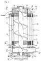
- the numeral 1 denotes a filtration cylinder for a screw drum filter; and 2 denotes a screw fitted to and extending through the cylindrical inner peripheral contour 3 of the filtration cylinder 1, the opposite ends thereof reaching an inlet case 4 and an outlet case 5.
- the filtration cylinder 1 is composed, between a front end plate 6 and a rear end plate 7, of an approximately horizontally extending alternately superposed array of a number of fixed plates 8 having openings, typically circular, and a number of annular floating plates 9 having geometrically similar openings slightly larger in diameter than the openings in said fixed plates 8 and also having circular outer peripheries, wherein the small clearances between such plates provide filtration clearances for sludge to be processed.
- the cylindrical inner peripheral contour 3 of the filtration cylinder 1 is defined by the row of openings in the fixed plates 8 arranged.
- a plurality of support bars 10 (in Fig. 1, there appears only one positioned at the lower end) installed between the front and rear end plates 6 and 7 are inserted into the support holes in alternately disposed fixed plates 8 and spacers 11 and are fixed together in close contact with each other, while the floating plates 9 are positioned in spaces defined by the thickness of the spacers 11.
- These floating plates 9 are supported, position-controlled, rotated (around their own axes) and swung by a plurality of eccentric shafts 12 (in Fig. 1, there appears only one positioned at the upper end) contacting their outer peripheral edges exposed beyond the outer edges of the fixed plates 8.
- each fixed plate 8 is an inverted triangular plate having its three apexes cut off, with the support bars 10 and spacers 11 disposed at such apexes.
- the opening edge of the fixed plate 8 defines said cylindrical inner peripheral contour 3 and in Fig. 2 the floating plate 9 disposed on either side of said plate 8 swings in a plane surrounded by three spaces 11 and within a range in which the opening edge 13 thereof does not enter the cylindrical inner peripheral contour 3.
- Three eccentric shafts 12 are rotatably installed between intermediate extensions 7a, 7b, 7c on the individual sides of the rear end plate 7, which has a basic shape congruent to the shape of the fixed plate 8, and intermediate extensions 6a, 6b, 6c (Fig. 4) of the front end plate 6 corresponding thereto, and are driven in operative connection to the screw 2 by a gear train 14 (Fig. 1) disposed outside the outlet case 5.
- the eccentric shafts 12 may be driven separately from or independently of the screw 2 by some other driving mechanism.
- the circular outer peripheral edge of the floating plate 9 projects beyond the middle portions of the three longer sides of the fixed plate 8 within said range of swing movement and is contacted and supported by the three eccentric shafts 12, all of the floating plates 9 being rotatively swung by the eccentric rotation of these eccentric shafts 12.
- Each eccentric shaft 12 is of integrated construction having small-diametered eccentric shafts 12a projecting from the opposite ends of the main body shaft; therefore, when the outer periphery of the main body shaft effects rotary movement, the floating plate 9 is frictionally driven thereby and also produces rotary motion.
- the floating plate 9 may be such that it is supported by the eccentric shafts only at its portions exposed beyond the adjacent longer sides of the fixed plate 8. This means that the floating plate 9 suffices for the purpose so long as it is constructed such that at least two equi-level regions in the lower portions of the floating plate 9 are exposed beyond the outer edge of the fixed plate 8.
- Fig. 3 shows the screw 2 rotated clockwise through 25° from the state shown in Fig. 2 and the eccentric shafts 12 rotated concurrently therewith counterclockwise through about 45°.
- the opening edge 13 of the floating plate 9 and the uppermost portion of the opening edge of the fixed plate 8 are separated farthest from each other and the lowermost portions of opening edges of the two plates approximately coincide with each other
- the opening edge 13 of the floating plate and the portion of the opening edge of the fixed plate opposed to the eccentric shaft 12 positioned at 30° lower right are separated farthest and their portions opposed to the eccentric shaft 12 positioned at 30° upper right approximately coincide with each other.
- the floating plate 9 swings in this manner in operative connection with the rotation of the screw 2.
- Fig. 4 is a section taken along the line B-B in Fig. 1, showing the construction of the inside of the inlet case 4.
- An U-type curved plate 16 having a number of small holes 15 and also having a curved surface slidably contacting the outer edges of the vanes of the screw 2 is installed in the case 4 to extend between the front and rear walls of the case (see Fig. 1), so as to receive sludge to be processed from the open upper end.
- the lower end of the inlet case 4 may be formed in a bag type having no opening 4a, in which case the introduced sludge to be processed will be fed as it is to the filtration cylinder 1.
- the sludge to be processed that is gradually compressed in the filtration cylinder 1 by the screw 2 is radially filtered through the filtration clearances permanently (slidingly) regenerated between the floating plates 9 and the fixed plates 8 by the aforesaid swing of the floating plates 9, and the filtrate water component moves along the peripheral edges of these plates 8 and 9, the greater part of which water component reaches the lower ends of the fixed plates 8 positioned between two lower eccentric shafts 12 and then flows down therefrom, without flowing into the bearings for the eccentric shafts 12, so that it does not cause corrosion or wear of the bearings.
- the thus compressed and concentrated cake from the sludge is discharged through the outlet port 5a at the lower end of the outlet case 5.
- Figs. 5 and 6 are views showing preferred opening shapes for the fixed and floating plates 8 and 9, respectively, and the contours of their opening edges 3a and 13a are defined by rounded wavelike closed curves along the circular base lines.
- the opening edge 13a of the floating plate is somewhat larger than the opening edge 3a of the fixed plate so that the former does not enter the latter during operation.
- the opening edges 3a and 13a maintain the area of contact with the sludge to be processed somewhat larger than in the case of a simple circle, thereby increasing the filtration efficiency.
- the opening edges are not pointed as in the case of triangular waves, there is obtained an effect that suspended particles hardly accumulate.
- the present invention provides a screw drum device including a means (eccentric shafts 12) for direct contact with the floating plates and having a simple construction adapted to prevent the filtrate water from entering the bearings for said means.
- the openings in the fixed and floating plate may be in the shape of rounded waves so as to provide a long-life screw drum device having a high degree of filtration efficiency.
Landscapes
- Chemical & Material Sciences (AREA)
- Chemical Kinetics & Catalysis (AREA)
- Filtration Of Liquid (AREA)
- Treatment Of Sludge (AREA)
Applications Claiming Priority (3)
| Application Number | Priority Date | Filing Date | Title |
|---|---|---|---|
| JP34278998 | 1998-12-02 | ||
| JP34278998 | 1998-12-02 | ||
| PCT/JP1999/006436 WO2000032292A1 (fr) | 1998-12-02 | 1999-11-18 | Dispositif de filtration de type tambour a vis |
Publications (2)
| Publication Number | Publication Date |
|---|---|
| EP1052007A1 true EP1052007A1 (fr) | 2000-11-15 |
| EP1052007A4 EP1052007A4 (fr) | 2001-04-25 |
Family
ID=18356520
Family Applications (1)
| Application Number | Title | Priority Date | Filing Date |
|---|---|---|---|
| EP99972941A Withdrawn EP1052007A4 (fr) | 1998-12-02 | 1999-11-18 | Dispositif de filtration de type tambour a vis |
Country Status (9)
| Country | Link |
|---|---|
| US (1) | US6338411B1 (fr) |
| EP (1) | EP1052007A4 (fr) |
| KR (1) | KR20010034447A (fr) |
| CN (1) | CN1154529C (fr) |
| AU (1) | AU763047B2 (fr) |
| CA (1) | CA2319075A1 (fr) |
| NZ (1) | NZ506137A (fr) |
| TW (1) | TW490312B (fr) |
| WO (1) | WO2000032292A1 (fr) |
Cited By (3)
| Publication number | Priority date | Publication date | Assignee | Title |
|---|---|---|---|---|
| EP2363278A1 (fr) * | 2010-03-01 | 2011-09-07 | Alonso Sánchez Osma | Dispositif pour séparer de la matière solide de l'eau |
| EP3613489A4 (fr) * | 2017-04-21 | 2020-11-04 | Wu, Yunping | Séparateur solide-liquide en spirale stratifié à mouvement pendulaire de torsion |
| EP3613574A4 (fr) * | 2017-04-21 | 2020-12-02 | Wu, Yunping | Séparateur solide-liquide en spirale stratifié à arbres multiples avec mouvement pendulaire |
Families Citing this family (25)
| Publication number | Priority date | Publication date | Assignee | Title |
|---|---|---|---|---|
| JP4480864B2 (ja) * | 2000-08-07 | 2010-06-16 | 株式会社鶴見製作所 | スクリュー式濾過脱水装置に係る環状可動プレート |
| KR100413164B1 (ko) * | 2001-06-27 | 2003-12-31 | (주)오에치케이 | 스크류식 고체·액체분리장치 |
| KR100413165B1 (ko) * | 2001-06-27 | 2003-12-31 | (주)오에치케이 | 스크류식 고체·액체분리장치 |
| TW200632147A (fr) * | 2004-11-12 | 2006-09-16 | ||
| KR100714417B1 (ko) * | 2006-06-09 | 2007-05-04 | 주식회사 유천엔지니어링 | 다중원판 외통회전식 스크류타입의 슬러지 탈수장치 |
| US7905994B2 (en) * | 2007-10-03 | 2011-03-15 | Moses Lake Industries, Inc. | Substrate holder and electroplating system |
| US20090188553A1 (en) * | 2008-01-25 | 2009-07-30 | Emat Technology, Llc | Methods of fabricating solar-cell structures and resulting solar-cell structures |
| CN101507887B (zh) * | 2008-12-27 | 2011-11-23 | 上海索原环境科技有限公司 | 蠕动筛型分离机及其实现方法 |
| US8262894B2 (en) | 2009-04-30 | 2012-09-11 | Moses Lake Industries, Inc. | High speed copper plating bath |
| KR100978040B1 (ko) * | 2010-02-22 | 2010-08-26 | (주)에이알케이 | 슬러지 탈수장치 |
| EP2560924B1 (fr) * | 2010-04-21 | 2015-01-28 | The Warb Trust (no. 1 Trust 13337/99) | Système et procédé de traitement de boue |
| KR101189731B1 (ko) | 2010-07-30 | 2012-10-10 | (주)태화종합기술공사 | 스크류식 탈수기 |
| JP4871437B1 (ja) | 2011-01-24 | 2012-02-08 | アムコン株式会社 | 固液分離装置 |
| KR101180639B1 (ko) * | 2012-07-27 | 2012-09-18 | 최갑진 | 유동식 스크류 탈수장치 |
| JP5854958B2 (ja) * | 2012-09-19 | 2016-02-09 | 株式会社鶴見製作所 | 固液分離装置 |
| CN103835058A (zh) * | 2012-11-20 | 2014-06-04 | 吴江市利群纺织有限公司 | 喷水纺织机进水滤网机构 |
| WO2015004707A1 (fr) | 2013-07-08 | 2015-01-15 | アムコン株式会社 | Dispositif de concentration d'un objet à traiter |
| CN105058842B (zh) * | 2015-06-11 | 2018-01-23 | 安尼康(福建)环保设备有限公司 | 一种具有半割环的固液分离装置 |
| CN105500755A (zh) * | 2016-01-27 | 2016-04-20 | 河南工程学院 | 无磨损磨片式固液分离机 |
| CN105642001A (zh) * | 2016-03-07 | 2016-06-08 | 东莞市威力固电路板设备有限公司 | 滚筒过滤系统 |
| CN108211450B (zh) * | 2018-03-19 | 2020-04-24 | 亚太泵阀有限公司 | 一种污水过滤处理装置 |
| CN110721896A (zh) * | 2019-10-24 | 2020-01-24 | 安徽省环境科学研究院 | 一种高效节水淀粉浆渣分离筛及分离方法 |
| CN110893293B (zh) * | 2019-12-08 | 2022-01-11 | 江苏佳森环保科技有限公司 | 一种具有自动清洗功能的废水处理设备 |
| CN113521839B (zh) * | 2021-08-17 | 2023-01-31 | 浙江理工大学科技与艺术学院 | 一种可进行印染污水再利用的循环式节能设备 |
| CN216155724U (zh) * | 2021-09-02 | 2022-04-01 | 吴云萍 | 一种具有可拆卸式驱动装置的无磨损叠片螺旋脱水设备 |
Family Cites Families (9)
| Publication number | Priority date | Publication date | Assignee | Title |
|---|---|---|---|---|
| DE2225231C3 (de) * | 1972-05-24 | 1976-01-08 | Hidetoshi Chikuho Kaho Fukuoka Hata (Japan) | Schneckenpresse |
| US4177148A (en) * | 1978-03-03 | 1979-12-04 | Hach Chemical Company | Mechanical strainer |
| JPS59218298A (ja) * | 1983-05-27 | 1984-12-08 | Sanshu Kaken Kogyo Kk | 多板濾過部を有するスクリユープレス脱水機 |
| JPS6019012A (ja) * | 1983-07-12 | 1985-01-31 | Sasaki Goro | スクリユ−式濾過方法およびその装置 |
| US4781615A (en) | 1987-08-31 | 1988-11-01 | Amp Incorporated | Cable terminating cover retention system |
| GB8825259D0 (en) * | 1988-10-25 | 1988-11-30 | Byers E V | Rotary screening device |
| JP2501173Y2 (ja) * | 1991-02-27 | 1996-06-12 | 石垣機工株式会社 | 外筒回転式スクリュ―プレス |
| JPH0763873B2 (ja) * | 1991-12-20 | 1995-07-12 | 富国工業株式会社 | 回転篩 |
| JP2501173B2 (ja) | 1993-06-18 | 1996-05-29 | 株式会社日立製作所 | 多段再生中継装置 |
-
1999
- 1999-11-18 KR KR1020007008230A patent/KR20010034447A/ko not_active Ceased
- 1999-11-18 EP EP99972941A patent/EP1052007A4/fr not_active Withdrawn
- 1999-11-18 CN CNB998025828A patent/CN1154529C/zh not_active Expired - Fee Related
- 1999-11-18 WO PCT/JP1999/006436 patent/WO2000032292A1/fr not_active Ceased
- 1999-11-18 AU AU11827/00A patent/AU763047B2/en not_active Ceased
- 1999-11-18 CA CA002319075A patent/CA2319075A1/fr not_active Abandoned
- 1999-11-18 NZ NZ506137A patent/NZ506137A/xx unknown
- 1999-11-18 US US09/601,252 patent/US6338411B1/en not_active Expired - Fee Related
-
2000
- 2000-06-09 TW TW089111296A patent/TW490312B/zh not_active IP Right Cessation
Cited By (3)
| Publication number | Priority date | Publication date | Assignee | Title |
|---|---|---|---|---|
| EP2363278A1 (fr) * | 2010-03-01 | 2011-09-07 | Alonso Sánchez Osma | Dispositif pour séparer de la matière solide de l'eau |
| EP3613489A4 (fr) * | 2017-04-21 | 2020-11-04 | Wu, Yunping | Séparateur solide-liquide en spirale stratifié à mouvement pendulaire de torsion |
| EP3613574A4 (fr) * | 2017-04-21 | 2020-12-02 | Wu, Yunping | Séparateur solide-liquide en spirale stratifié à arbres multiples avec mouvement pendulaire |
Also Published As
| Publication number | Publication date |
|---|---|
| AU1182700A (en) | 2000-06-19 |
| WO2000032292A1 (fr) | 2000-06-08 |
| AU763047B2 (en) | 2003-07-10 |
| EP1052007A4 (fr) | 2001-04-25 |
| US6338411B1 (en) | 2002-01-15 |
| KR20010034447A (ko) | 2001-04-25 |
| TW490312B (en) | 2002-06-11 |
| CN1289266A (zh) | 2001-03-28 |
| CN1154529C (zh) | 2004-06-23 |
| CA2319075A1 (fr) | 2000-06-08 |
| NZ506137A (en) | 2002-10-25 |
Similar Documents
| Publication | Publication Date | Title |
|---|---|---|
| US6338411B1 (en) | Screw drum type filtration device | |
| AU738767B2 (en) | Filter of processing volume ratio adapted screw press type | |
| KR100672218B1 (ko) | 스크류식 고체ㆍ액체분리장치 | |
| CN100519450C (zh) | 螺杆式淤泥脱水装置 | |
| JP4817473B2 (ja) | 可動板分割駆動式スクリュープレス装置 | |
| JP2541914B2 (ja) | 非回転ろ過プレ―トの摺動機構を有する連続ろ過装置 | |
| JP4562217B2 (ja) | 可動板回転駆動式スクリュープレス装置 | |
| HK1034917A (en) | Screw drum type filtration device | |
| JP4480864B2 (ja) | スクリュー式濾過脱水装置に係る環状可動プレート | |
| CN217898047U (zh) | 一种过滤柴油中微小颗粒的高效柴油滤芯 | |
| CN118901675B (zh) | 一种贝类捕集器及其捕集方法 | |
| CN117463054B (zh) | 一种市政污水处理装置 | |
| KR200347162Y1 (ko) | 스크류식 여과장치 | |
| CN117883908B (zh) | 一种前置过滤器 | |
| JP7063099B2 (ja) | 固液分離装置および固液分離装置の組立方法 | |
| RU2248238C1 (ru) | Распределительная головка вращающегося вакуумного фильтра | |
| JP3024020U (ja) | 濾過脱水装置 | |
| CN223474750U (zh) | 一种用于工业废气处理的洗涤塔 | |
| JP3347305B2 (ja) | 汚水・汚泥の濃縮装置 | |
| JPH0510883Y2 (fr) | ||
| JP4041318B2 (ja) | スクリュー式濾過脱水装置 | |
| JPS6131062Y2 (fr) | ||
| JPH03127601A (ja) | 金属切粉等の加工液の濾過装置 | |
| JP2007289839A (ja) | 多重円板脱水装置 | |
| JPS5916093Y2 (ja) | スカム分離除去装置 |
Legal Events
| Date | Code | Title | Description |
|---|---|---|---|
| PUAI | Public reference made under article 153(3) epc to a published international application that has entered the european phase |
Free format text: ORIGINAL CODE: 0009012 |
|
| AK | Designated contracting states |
Kind code of ref document: A1 Designated state(s): AT BE CH CY DE DK ES FI FR GB GR IE IT LI LU MC NL PT SE |
|
| 17P | Request for examination filed |
Effective date: 20001206 |
|
| A4 | Supplementary search report drawn up and despatched |
Effective date: 20010308 |
|
| AK | Designated contracting states |
Kind code of ref document: A4 Designated state(s): AT BE CH CY DE DK ES FI FR GB GR IE IT LI LU MC NL PT SE |
|
| RBV | Designated contracting states (corrected) |
Designated state(s): DE FR GB IT NL |
|
| STAA | Information on the status of an ep patent application or granted ep patent |
Free format text: STATUS: THE APPLICATION HAS BEEN WITHDRAWN |
|
| 18W | Application withdrawn |
Effective date: 20050720 |