EP1052031A2 - Dispositif rotatif de tri - Google Patents
Dispositif rotatif de tri Download PDFInfo
- Publication number
- EP1052031A2 EP1052031A2 EP00108824A EP00108824A EP1052031A2 EP 1052031 A2 EP1052031 A2 EP 1052031A2 EP 00108824 A EP00108824 A EP 00108824A EP 00108824 A EP00108824 A EP 00108824A EP 1052031 A2 EP1052031 A2 EP 1052031A2
- Authority
- EP
- European Patent Office
- Prior art keywords
- conveyor
- feature
- discharge
- conveyors
- feed
- Prior art date
- Legal status (The legal status is an assumption and is not a legal conclusion. Google has not performed a legal analysis and makes no representation as to the accuracy of the status listed.)
- Granted
Links
Images






Classifications
-
- B—PERFORMING OPERATIONS; TRANSPORTING
- B65—CONVEYING; PACKING; STORING; HANDLING THIN OR FILAMENTARY MATERIAL
- B65G—TRANSPORT OR STORAGE DEVICES, e.g. CONVEYORS FOR LOADING OR TIPPING, SHOP CONVEYOR SYSTEMS OR PNEUMATIC TUBE CONVEYORS
- B65G47/00—Article or material-handling devices associated with conveyors; Methods employing such devices
- B65G47/52—Devices for transferring articles or materials between conveyors i.e. discharging or feeding devices
- B65G47/64—Switching conveyors
- B65G47/644—Switching conveyors by a pivoting displacement of the switching conveyor
- B65G47/648—Switching conveyors by a pivoting displacement of the switching conveyor about a vertical axis
-
- B—PERFORMING OPERATIONS; TRANSPORTING
- B07—SEPARATING SOLIDS FROM SOLIDS; SORTING
- B07C—POSTAL SORTING; SORTING INDIVIDUAL ARTICLES, OR BULK MATERIAL FIT TO BE SORTED PIECE-MEAL, e.g. BY PICKING
- B07C5/00—Sorting according to a characteristic or feature of the articles or material being sorted, e.g. by control effected by devices which detect or measure such characteristic or feature; Sorting by manually actuated devices, e.g. switches
- B07C5/36—Sorting apparatus characterised by the means used for distribution
-
- B—PERFORMING OPERATIONS; TRANSPORTING
- B65—CONVEYING; PACKING; STORING; HANDLING THIN OR FILAMENTARY MATERIAL
- B65G—TRANSPORT OR STORAGE DEVICES, e.g. CONVEYORS FOR LOADING OR TIPPING, SHOP CONVEYOR SYSTEMS OR PNEUMATIC TUBE CONVEYORS
- B65G29/00—Rotary conveyors, e.g. rotating discs, arms, star-wheels or cones
-
- B—PERFORMING OPERATIONS; TRANSPORTING
- B65—CONVEYING; PACKING; STORING; HANDLING THIN OR FILAMENTARY MATERIAL
- B65G—TRANSPORT OR STORAGE DEVICES, e.g. CONVEYORS FOR LOADING OR TIPPING, SHOP CONVEYOR SYSTEMS OR PNEUMATIC TUBE CONVEYORS
- B65G37/00—Combinations of mechanical conveyors of the same kind, or of different kinds, of interest apart from their application in particular machines or use in particular manufacturing processes
- B65G37/02—Flow-sheets for conveyor combinations in warehouses, magazines or workshops
Definitions
- the invention relates to rotating sorting devices for sorting piece goods according to the preamble of claim 1.
- sorting goods receptacles for example cross belts, bags or trays, run in Form an endless chain.
- the goods to be sorted are slanted onto the oval from the side given up.
- the sorted goods ejected by making the transport movement a horizontal or vertical movement is superimposed.
- Sorting devices are also known, but less common, in which the Sorted goods are guided in a circle around a central axis.
- sorting devices where the discharge with help is made by stationary bumpers in the path of the Sorted goods are swung in.
- Other sorting devices use co-rotating ones Discharge devices.
- the material to be conveyed is, for example, in pockets or Peel; they are tilted, raised or lowered at the transfer point.
- the number of discharge devices is equal to the number of Tapping points or the number of sorting goods.
- the object of the present invention is a rotating sorting device to specify, which manages with a simple mechanism and the use of simple, inexpensive and reliable transmission devices for energy and Control signals enabled.
- the sorting device consists of any one A large number of tapping points arranged in a circle around a central axis stationary linear feeder and one continuously around the central axis rotating linear conveyor.
- Belt conveyors are suitable as feed and discharge conveyors, Roller conveyors, slides or the like. Since the conveyor rotates around a central axis, the energy and signal transmission takes place from this point.
- the rotating construction can be kept very simple and permanent.
- Another advantage is that there is not a discharge device at every tapping point must be provided. Rather, it is sufficient to control the feed of the discharge conveyor start and stop.
- the transfer point is between Feeders and conveyors near the axis, because here the tangential Speed component is small.
- the transfer point is chosen so that the The speed at which the conveyor moves past the transfer point is the same the transport speed of the feed conveyor. In this way, the sorted goods optimally handed over.
- a particularly problem-free handover can be achieved by the conveyor receives a cross slope in the area of the transfer point, which corresponds to the slope of the end of the Feed conveyor is adjusted.
- the end of the feed conveyor can be designed as a slide.
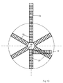
- the longitudinal axes of the conveyors are against the Direction of rotation pivoted from the radial.
- the advantage of this arrangement is that that the superimposition of tangential and radial movement of the goods to be sorted rotating conveyor a purely radial movement of the goods to be sorted at the removal point Consequence.
- the goods to be sorted can therefore also be at a high rotational speed Do not miss the tapping point.
- a A plurality of discharge conveyors are provided. These then rotate like spokes Rades around the central axis and are powered and powered by the axis Control signals supplied.
- An increase in the number of delivery points can be achieved by: several concentric circles are arranged around the central axis.
- the conveyors are of different lengths, telescopic and / or linearly movable educated.
- the tapping points are different Heights arranged.
- the conveyors are then designed with different slopes.
- the incline of the feed and / or discharge conveyors can also be changed in a controlled manner.
- the feed and / or discharge conveyors are belt conveyors realized.
- Alternative embodiments are roller conveyors or slides.
- At least one discharge conveyor contains a partial conveyor, which can be independently rotated, raised and lowered, tilted and / or With the aid of such a partial conveyor, the sorted goods can be moved through Lifting, lowering, turning, etc. brought into any position that is optimal for further processing become.
- each partial conveyor can have its own Tapping point can be assigned.
- the tapping points rotate in a controlled manner around the central axis.
- the Transfer from the conveyor to a specific delivery point is accelerated as required or be slowed down.
- the tapping points are on an annular ring Conveyor track. Thanks to this measure, it is possible to use ordinary boxes as delivery points or boxes to use.
- the tapping points themselves are as annular, possibly concentric conveyor tracks.
- the rotating sorting device is at least assigned a tangential conveyor track. This enables the bringing in of Sorted goods to the device according to the invention as well as the removal of the sorted Goods.
- Sorting devices there are two or more Sorting devices, wherein at least one of the removal points, formed by a chute, a belt conveyor or a roller conveyor that has a sorting device Sorted goods are transferred to a feed conveyor of the other sorting device Coupling several sorting devices can be the number of points of delivery and the Increase sorting performance significantly.
- the sorting devices can be next to each other depending on the space available or stand on top of each other.
- Fig. 1 as a top view and Fig. 2 as a side view show a first rotating Sorting device I.
- the conveyor 20, 21 sit on a hub 22, the rotates continuously around the central axis 0, in the present case counterclockwise.
- alternate short discharge conveyor 20 and long discharge conveyor 21 In order to be able to operate the two concentric circles of tapping points 30, 31, alternate short discharge conveyor 20 and long discharge conveyor 21.
- Conveyed goods 1, 2, 3, 4, 5 are located on the four feed conveyors 10, 11, the conveyed goods 2 has almost reached the transfer point.
- Other goods 6, 7 are also on the conveyors 20, 21.
- the number of discharge conveyors 20, 21 is significantly less than the number of removal points 30, 31, so that overall a very simple mechanism and a simple control electronics results.
- FIG. 3 shows a second embodiment of the rotating sorting device.
- Some delivery points are as Conveyor belts 32 realized.
- Fig. 4 shows a plan view of a formed from two rotating sorting devices I, II Sorting system.
- the conveyors 20 of the sorting device I transfer the conveyed goods directly on a first conveyor belt 23, which the goods to be conveyed onto the feed conveyor 10 Sorting device II passes in the same way, the discharge 20 of the Sorting device II the goods to be conveyed directly onto a second conveyor belt 24 Conveyed goods are transferred to one of the feed conveyors 10 of the first sorting device I.
- two rotating sorting devices I, II allows the number of Increase tapping points 30. If the throughput of the sorting system is also to be increased, this can be achieved by increasing the number of feeders 10, 11.
- the conveyors 20, 21 also serve as intermediate buffers.
- Fig. 5 shows a sorting system which consists of two rotating one above the other Sorting devices I, II is formed.
- the goods are conveyed with the help of a Transport device, for example a lift system, of the one sorting device I, II passed to the other sorting device II, I.
- the ends 11 of the feed conveyor 10 are as Slide realized.
- FIG. 6 shows a top view of a third rotating sorting device. You can see six Conveyors 20 rotating about the central axis 0. Each conveyor 20 has two or three partial conveyors 25, which can be rotated, raised and lowered, tilted and / or independently are movable. These partial conveyors 25 make it possible to sort the goods into the Bring further transport to optimal position.
- Fig. 7 shows a purely schematic side view of one of the discharge conveyor 20 in Fig. 6.
- FIG. 8 shows a further discharge conveyor 20 from FIG. 6 in a purely schematic manner.
- Partial conveyor 25 which are pivoted downward from the level of the discharge conveyor 20 can.
- Each partial conveyor 25 is assigned its own take-off point 33. Through this Increasing the number of delivery points further increases the flexibility of the sorting device.
- FIG. 9 shows a top view of a fourth rotating sorting device in a purely schematic manner.
- Such curved transport tracks can be used the radial and tangential speed vectors of the goods to be sorted Delivery point vary within wide limits.
- FIG. 10 shows a top view of a fifth rotating sorting device in a purely schematic manner.
- both the feed conveyor 10 and the discharge conveyor 20 and the removal conveyor 34 as Roller conveyor trained.
- FIG. 11 shows a top view of a sixth rotating sorting device in a purely schematic manner.
- the feeders are omitted for the sake of simplicity.
- the conveyor 20 rotate continuously around the central axis 0. You hand over the conveyed goods 1 to take-off points 30, which in turn stand on an annular conveyor track 35 designed as a roller conveyor and can be on this procedure.
- a second annular conveyor can be seen concentric to the annular conveyor track 35 Conveyor track 36. Finally, one can also see a roller track tangential conveyor track 37. Thanks to the conveyor tracks 35, 36, 37, the goods 1 can Sorting device supplied and removed after successful sorting. For this purpose, the conveyed goods 1 with the help of commercially available manipulators (not shown) between the different conveyor tracks 35, 36, 37 and the feed and Conveyors 10, 20 implemented.
- Fig. 12 shows a purely schematic side view of a feed conveyor 10, 11 and discharge conveyor 20 existing subunit of a sorting device.
- the feed conveyor 10 has one adjustable incline.
- the conveyor 20 has a cross slope that the slope of the End 11 of the feed conveyor 10 corresponds.
- FIG. 13 also shows a further sub-unit schematically. You can see two around them central axis 0 rotating discharge conveyor 20, the slope of which can be changed in a controlled manner. This makes it possible to remove the tapping points 30, which are arranged one above the other in three levels. 31, 32 to use specifically.
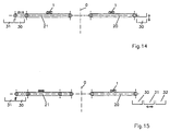
- the 14 shows schematically the side view of two rotating around the central axis 0 min Discharge conveyor 20, 21.
- the right discharge conveyor 20 is adjustable in height Tapping point 30 assigned.
- the left conveyor 21 are two concentric Tapping points 30, 31 assigned. In order to be able to use them specifically, the length of the Abierers 21 telescopically changeable.
- 15 shows a purely schematic side view of two further discharge conveyors 20, 21 right discharge conveyor 20 are assigned to three concentric removal points 30, 31, 32 are radially displaceable, so that the sorted goods 1 are directed to one of the take-off points 30, 31, 32 can be delivered.
- the left-hand conveyor 21, on the other hand, can be moved radially, so that the sorted goods are also here can be delivered specifically to one of the concentric tapping points 30, 31.
- FIG. 16 shows a plan view of a seventh sorting device. This has three around central axis 0 rotating discharge conveyor 20, the sorting 1 in one of the Deliver tapping points 30. As can be seen from the side view shown in FIG. 17, the feed conveyor 10 is arranged in a level below the level of the discharge conveyor 20. The End 11 of the feed conveyor 10 thus rises to the level of the discharge conveyor 20. The handover of the Sorted goods 1 take place in the area of the central axis 11 as soon as the longitudinal axes of Feed conveyor 10, 11 and discharge conveyor 20 are aligned.
- Feed conveyor 11 and discharge conveyor 20 are designed as slides. This Construction is characterized by a special simplicity.
- Fig. 19 shows purely schematically the side view of a discharge conveyor 20, the one as a slide trained tapping point 30 is assigned.
Landscapes
- Engineering & Computer Science (AREA)
- Mechanical Engineering (AREA)
- Discharge Of Articles From Conveyors (AREA)
- Branching, Merging, And Special Transfer Between Conveyors (AREA)
- Sorting Of Articles (AREA)
- Combined Means For Separation Of Solids (AREA)
- Intermediate Stations On Conveyors (AREA)
- Feeding Of Articles To Conveyors (AREA)
- Specific Conveyance Elements (AREA)
Applications Claiming Priority (2)
| Application Number | Priority Date | Filing Date | Title |
|---|---|---|---|
| DE29908272U | 1999-05-08 | ||
| DE29908272U DE29908272U1 (de) | 1999-05-08 | 1999-05-08 | Rotierende Sortiervorrichtung |
Publications (3)
| Publication Number | Publication Date |
|---|---|
| EP1052031A2 true EP1052031A2 (fr) | 2000-11-15 |
| EP1052031A3 EP1052031A3 (fr) | 2003-07-30 |
| EP1052031B1 EP1052031B1 (fr) | 2006-01-11 |
Family
ID=8073351
Family Applications (1)
| Application Number | Title | Priority Date | Filing Date |
|---|---|---|---|
| EP00108824A Expired - Lifetime EP1052031B1 (fr) | 1999-05-08 | 2000-04-26 | Dispositif rotatif de tri |
Country Status (6)
| Country | Link |
|---|---|
| EP (1) | EP1052031B1 (fr) |
| JP (1) | JP2000343045A (fr) |
| AT (1) | ATE315446T1 (fr) |
| DE (2) | DE29908272U1 (fr) |
| DK (1) | DK1052031T3 (fr) |
| ES (1) | ES2255912T3 (fr) |
Cited By (3)
| Publication number | Priority date | Publication date | Assignee | Title |
|---|---|---|---|---|
| CN106552771A (zh) * | 2016-12-05 | 2017-04-05 | 顺丰科技有限公司 | 无人机物流地面收纳平台系统及控制方法 |
| IT202200015579A1 (it) * | 2022-07-25 | 2024-01-25 | Gd Spa | Apparato e metodo per l’immagazzinamento di articoli |
| CH721113A1 (de) * | 2023-09-07 | 2025-03-14 | Ferag Ag | Vorrichtung und verfahren zum beschicken von transporttaschen eines hängeförderers |
Families Citing this family (4)
| Publication number | Priority date | Publication date | Assignee | Title |
|---|---|---|---|---|
| TWI415779B (zh) * | 2010-10-20 | 2013-11-21 | Inotera Memories Inc | 旋轉式儲存搬運系統及其控制方法 |
| CN112090765B (zh) * | 2019-06-17 | 2022-03-08 | 北京旷视机器人技术有限公司 | 货物分拣系统及方法 |
| WO2024004081A1 (fr) * | 2022-06-29 | 2024-01-04 | 武彦 塩川 | Dispositif de tri |
| CN116637827B (zh) * | 2023-05-29 | 2023-11-03 | 苏州众捷汽车零部件股份有限公司 | 一种离合器的气密性检测装置 |
Family Cites Families (3)
| Publication number | Priority date | Publication date | Assignee | Title |
|---|---|---|---|---|
| US1753036A (en) * | 1928-04-20 | 1930-04-01 | Timothy W Williamson | Mail-sorting apparatus |
| US5284252A (en) * | 1991-11-13 | 1994-02-08 | United Parcel Service Of America, Inc. | Automatic rotary sorter |
| US6227377B1 (en) * | 1997-09-09 | 2001-05-08 | United Parcel Service Of America, Inc. | Automated array sorter for conveyors |
-
1999
- 1999-05-08 DE DE29908272U patent/DE29908272U1/de not_active Expired - Lifetime
-
2000
- 2000-04-26 AT AT00108824T patent/ATE315446T1/de not_active IP Right Cessation
- 2000-04-26 ES ES00108824T patent/ES2255912T3/es not_active Expired - Lifetime
- 2000-04-26 DE DE50012039T patent/DE50012039D1/de not_active Expired - Lifetime
- 2000-04-26 EP EP00108824A patent/EP1052031B1/fr not_active Expired - Lifetime
- 2000-04-26 DK DK00108824T patent/DK1052031T3/da active
- 2000-05-08 JP JP2000134781A patent/JP2000343045A/ja active Pending
Cited By (5)
| Publication number | Priority date | Publication date | Assignee | Title |
|---|---|---|---|---|
| CN106552771A (zh) * | 2016-12-05 | 2017-04-05 | 顺丰科技有限公司 | 无人机物流地面收纳平台系统及控制方法 |
| CN106552771B (zh) * | 2016-12-05 | 2019-02-12 | 顺丰科技有限公司 | 无人机物流地面收纳平台系统及控制方法 |
| IT202200015579A1 (it) * | 2022-07-25 | 2024-01-25 | Gd Spa | Apparato e metodo per l’immagazzinamento di articoli |
| WO2024023639A1 (fr) * | 2022-07-25 | 2024-02-01 | G.D S.P.A. | Appareil et procédé de stockage d'articles |
| CH721113A1 (de) * | 2023-09-07 | 2025-03-14 | Ferag Ag | Vorrichtung und verfahren zum beschicken von transporttaschen eines hängeförderers |
Also Published As
| Publication number | Publication date |
|---|---|
| EP1052031A3 (fr) | 2003-07-30 |
| DK1052031T3 (da) | 2006-05-15 |
| DE29908272U1 (de) | 2001-02-22 |
| DE50012039D1 (de) | 2006-04-06 |
| ES2255912T3 (es) | 2006-07-16 |
| JP2000343045A (ja) | 2000-12-12 |
| EP1052031B1 (fr) | 2006-01-11 |
| ATE315446T1 (de) | 2006-02-15 |
Similar Documents
| Publication | Publication Date | Title |
|---|---|---|
| DE69720125T2 (de) | Transporteinheit für Produkte | |
| DE69001317T2 (de) | Automatischer hoch- und niedergeschwindigkeits-sortierfoerderer. | |
| EP3652096B1 (fr) | Dispositif de stockage et de convoyeur et procédé de fonctionnement du dispositif de stockage et de convoyeur | |
| DE4224609A1 (de) | Fördervorrichtung für Zigaretten | |
| DE102009016593A1 (de) | Vorrichtung zum Transport von Vorformlingen | |
| DE8714976U1 (de) | Sortiermaschine | |
| EP0320697B1 (fr) | Dispositif de fabrication et d'emballage de cigarettes | |
| EP0727370B1 (fr) | Installation de transport | |
| EP1052031B1 (fr) | Dispositif rotatif de tri | |
| DE60018456T2 (de) | Transportvorrichtung von einzelteilen mit einer verteilungsvorrichtung und blasformanlage zu herstellung von behältern mit einer solchen transportvorrichtung | |
| EP0648696B1 (fr) | Dispositif pour transférer des objets sur des voies de transport | |
| EP3802382B1 (fr) | Dispositif de transport et procédé de transport d'applicateurs de tampon | |
| EP0718219A2 (fr) | Dispositif pour individualiser des objets | |
| DE102015214869B4 (de) | Fördervorrichtung zum Transport und zur Dosierung von Zuführ-Teilen | |
| DE2945213C2 (de) | Förderbahn mit Eingabe- und Abwerfvorrichtungen | |
| DE69411786T2 (de) | Stapelvorrichtung | |
| DE1648459C3 (de) | Vorrichtung zum Zufuhren von zylindrischen Glaskörpern zu einer Kontrollstation | |
| EP4166485B1 (fr) | Dispositif de transport | |
| DE3510698C2 (fr) | ||
| DE3914360C2 (fr) | ||
| DE2849724C2 (de) | Vorrichtung zum Ausrichten von Flaschen | |
| DE3826638A1 (de) | Vorrichtung zum transportieren von waren | |
| DE19717141C2 (de) | Vorrichtung zum Sortieren und Verteilen von Stückgütern | |
| DD148602A1 (de) | Einrichtung zum vereinzeln und sortieren von staeben | |
| EP0450556A2 (fr) | Appareil de transfert |
Legal Events
| Date | Code | Title | Description |
|---|---|---|---|
| PUAI | Public reference made under article 153(3) epc to a published international application that has entered the european phase |
Free format text: ORIGINAL CODE: 0009012 |
|
| AK | Designated contracting states |
Kind code of ref document: A2 Designated state(s): AT BE CH CY DE DK ES FI FR GB GR IE IT LI LU MC NL PT SE |
|
| AX | Request for extension of the european patent |
Free format text: AL;LT;LV;MK;RO;SI |
|
| PUAL | Search report despatched |
Free format text: ORIGINAL CODE: 0009013 |
|
| AK | Designated contracting states |
Designated state(s): AT BE CH CY DE DK ES FI FR GB GR IE IT LI LU MC NL PT SE |
|
| AX | Request for extension of the european patent |
Extension state: AL LT LV MK RO SI |
|
| RIC1 | Information provided on ipc code assigned before grant |
Ipc: 7B 65G 47/64 B Ipc: 7B 07C 5/36 A |
|
| 17P | Request for examination filed |
Effective date: 20031021 |
|
| 17Q | First examination report despatched |
Effective date: 20040217 |
|
| AKX | Designation fees paid |
Designated state(s): AT BE CH CY DE DK ES FI FR GB GR IE IT LI LU MC NL PT SE |
|
| GRAP | Despatch of communication of intention to grant a patent |
Free format text: ORIGINAL CODE: EPIDOSNIGR1 |
|
| GRAS | Grant fee paid |
Free format text: ORIGINAL CODE: EPIDOSNIGR3 |
|
| GRAA | (expected) grant |
Free format text: ORIGINAL CODE: 0009210 |
|
| AK | Designated contracting states |
Kind code of ref document: B1 Designated state(s): AT BE CH CY DE DK ES FI FR GB GR IE IT LI LU MC NL PT SE |
|
| PG25 | Lapsed in a contracting state [announced via postgrant information from national office to epo] |
Ref country code: FI Free format text: LAPSE BECAUSE OF FAILURE TO SUBMIT A TRANSLATION OF THE DESCRIPTION OR TO PAY THE FEE WITHIN THE PRESCRIBED TIME-LIMIT Effective date: 20060111 Ref country code: IE Free format text: LAPSE BECAUSE OF FAILURE TO SUBMIT A TRANSLATION OF THE DESCRIPTION OR TO PAY THE FEE WITHIN THE PRESCRIBED TIME-LIMIT Effective date: 20060111 |
|
| REG | Reference to a national code |
Ref country code: CH Ref legal event code: EP |
|
| REG | Reference to a national code |
Ref country code: IE Ref legal event code: FG4D Free format text: LANGUAGE OF EP DOCUMENT: GERMAN |
|
| REF | Corresponds to: |
Ref document number: 50012039 Country of ref document: DE Date of ref document: 20060406 Kind code of ref document: P |
|
| REG | Reference to a national code |
Ref country code: CH Ref legal event code: NV Representative=s name: PATENTANWAELTE SCHAAD, BALASS, MENZL & PARTNER AG |
|
| REG | Reference to a national code |
Ref country code: SE Ref legal event code: TRGR |
|
| PG25 | Lapsed in a contracting state [announced via postgrant information from national office to epo] |
Ref country code: MC Free format text: LAPSE BECAUSE OF NON-PAYMENT OF DUE FEES Effective date: 20060430 |
|
| REG | Reference to a national code |
Ref country code: DK Ref legal event code: T3 |
|
| GBT | Gb: translation of ep patent filed (gb section 77(6)(a)/1977) |
Effective date: 20060424 |
|
| PG25 | Lapsed in a contracting state [announced via postgrant information from national office to epo] |
Ref country code: PT Free format text: LAPSE BECAUSE OF FAILURE TO SUBMIT A TRANSLATION OF THE DESCRIPTION OR TO PAY THE FEE WITHIN THE PRESCRIBED TIME-LIMIT Effective date: 20060612 |
|
| REG | Reference to a national code |
Ref country code: ES Ref legal event code: FG2A Ref document number: 2255912 Country of ref document: ES Kind code of ref document: T3 |
|
| REG | Reference to a national code |
Ref country code: IE Ref legal event code: FD4D |
|
| ET | Fr: translation filed | ||
| PLBE | No opposition filed within time limit |
Free format text: ORIGINAL CODE: 0009261 |
|
| STAA | Information on the status of an ep patent application or granted ep patent |
Free format text: STATUS: NO OPPOSITION FILED WITHIN TIME LIMIT |
|
| 26N | No opposition filed |
Effective date: 20061012 |
|
| PG25 | Lapsed in a contracting state [announced via postgrant information from national office to epo] |
Ref country code: GR Free format text: LAPSE BECAUSE OF FAILURE TO SUBMIT A TRANSLATION OF THE DESCRIPTION OR TO PAY THE FEE WITHIN THE PRESCRIBED TIME-LIMIT Effective date: 20060412 |
|
| PG25 | Lapsed in a contracting state [announced via postgrant information from national office to epo] |
Ref country code: LU Free format text: LAPSE BECAUSE OF NON-PAYMENT OF DUE FEES Effective date: 20060426 |
|
| PG25 | Lapsed in a contracting state [announced via postgrant information from national office to epo] |
Ref country code: CY Free format text: LAPSE BECAUSE OF FAILURE TO SUBMIT A TRANSLATION OF THE DESCRIPTION OR TO PAY THE FEE WITHIN THE PRESCRIBED TIME-LIMIT Effective date: 20060111 |
|
| PGFP | Annual fee paid to national office [announced via postgrant information from national office to epo] |
Ref country code: DK Payment date: 20090423 Year of fee payment: 10 Ref country code: ES Payment date: 20090424 Year of fee payment: 10 |
|
| PGFP | Annual fee paid to national office [announced via postgrant information from national office to epo] |
Ref country code: FR Payment date: 20090420 Year of fee payment: 10 Ref country code: NL Payment date: 20090427 Year of fee payment: 10 Ref country code: IT Payment date: 20090428 Year of fee payment: 10 Ref country code: AT Payment date: 20090423 Year of fee payment: 10 Ref country code: SE Payment date: 20090427 Year of fee payment: 10 |
|
| PGFP | Annual fee paid to national office [announced via postgrant information from national office to epo] |
Ref country code: BE Payment date: 20090429 Year of fee payment: 10 |
|
| PGFP | Annual fee paid to national office [announced via postgrant information from national office to epo] |
Ref country code: CH Payment date: 20090427 Year of fee payment: 10 |
|
| PGFP | Annual fee paid to national office [announced via postgrant information from national office to epo] |
Ref country code: GB Payment date: 20090424 Year of fee payment: 10 |
|
| BERE | Be: lapsed |
Owner name: *PSB G.M.B.H. MATERIALFLUSS + LOGISTIK Effective date: 20100430 |
|
| REG | Reference to a national code |
Ref country code: NL Ref legal event code: V1 Effective date: 20101101 |
|
| EUG | Se: european patent has lapsed | ||
| REG | Reference to a national code |
Ref country code: CH Ref legal event code: PL |
|
| REG | Reference to a national code |
Ref country code: DK Ref legal event code: EBP |
|
| GBPC | Gb: european patent ceased through non-payment of renewal fee |
Effective date: 20100426 |
|
| REG | Reference to a national code |
Ref country code: FR Ref legal event code: ST Effective date: 20101230 |
|
| PG25 | Lapsed in a contracting state [announced via postgrant information from national office to epo] |
Ref country code: NL Free format text: LAPSE BECAUSE OF NON-PAYMENT OF DUE FEES Effective date: 20101101 Ref country code: AT Free format text: LAPSE BECAUSE OF NON-PAYMENT OF DUE FEES Effective date: 20100426 |
|
| PG25 | Lapsed in a contracting state [announced via postgrant information from national office to epo] |
Ref country code: CH Free format text: LAPSE BECAUSE OF NON-PAYMENT OF DUE FEES Effective date: 20100430 Ref country code: LI Free format text: LAPSE BECAUSE OF NON-PAYMENT OF DUE FEES Effective date: 20100430 |
|
| PG25 | Lapsed in a contracting state [announced via postgrant information from national office to epo] |
Ref country code: GB Free format text: LAPSE BECAUSE OF NON-PAYMENT OF DUE FEES Effective date: 20100426 Ref country code: IT Free format text: LAPSE BECAUSE OF NON-PAYMENT OF DUE FEES Effective date: 20100426 Ref country code: BE Free format text: LAPSE BECAUSE OF NON-PAYMENT OF DUE FEES Effective date: 20100430 |
|
| PG25 | Lapsed in a contracting state [announced via postgrant information from national office to epo] |
Ref country code: DK Free format text: LAPSE BECAUSE OF NON-PAYMENT OF DUE FEES Effective date: 20100503 |
|
| REG | Reference to a national code |
Ref country code: ES Ref legal event code: FD2A Effective date: 20110714 |
|
| PG25 | Lapsed in a contracting state [announced via postgrant information from national office to epo] |
Ref country code: ES Free format text: LAPSE BECAUSE OF NON-PAYMENT OF DUE FEES Effective date: 20110704 |
|
| PG25 | Lapsed in a contracting state [announced via postgrant information from national office to epo] |
Ref country code: ES Free format text: LAPSE BECAUSE OF NON-PAYMENT OF DUE FEES Effective date: 20100427 |
|
| PGFP | Annual fee paid to national office [announced via postgrant information from national office to epo] |
Ref country code: DE Payment date: 20110506 Year of fee payment: 12 |
|
| PG25 | Lapsed in a contracting state [announced via postgrant information from national office to epo] |
Ref country code: FR Free format text: LAPSE BECAUSE OF NON-PAYMENT OF DUE FEES Effective date: 20100430 |
|
| PG25 | Lapsed in a contracting state [announced via postgrant information from national office to epo] |
Ref country code: SE Free format text: LAPSE BECAUSE OF NON-PAYMENT OF DUE FEES Effective date: 20100427 |
|
| REG | Reference to a national code |
Ref country code: DE Ref legal event code: R119 Ref document number: 50012039 Country of ref document: DE Effective date: 20121101 |
|
| PG25 | Lapsed in a contracting state [announced via postgrant information from national office to epo] |
Ref country code: DE Free format text: LAPSE BECAUSE OF NON-PAYMENT OF DUE FEES Effective date: 20121101 |