EP1052041A2 - Moule avec masselotte sous pression - Google Patents
Moule avec masselotte sous pression Download PDFInfo
- Publication number
- EP1052041A2 EP1052041A2 EP00109888A EP00109888A EP1052041A2 EP 1052041 A2 EP1052041 A2 EP 1052041A2 EP 00109888 A EP00109888 A EP 00109888A EP 00109888 A EP00109888 A EP 00109888A EP 1052041 A2 EP1052041 A2 EP 1052041A2
- Authority
- EP
- European Patent Office
- Prior art keywords
- sealing element
- casting mold
- mold according
- pantry
- compressed gas
- Prior art date
- Legal status (The legal status is an assumption and is not a legal conclusion. Google has not performed a legal analysis and makes no representation as to the accuracy of the status listed.)
- Withdrawn
Links
- 238000005266 casting Methods 0.000 claims abstract description 43
- 238000007789 sealing Methods 0.000 claims abstract description 39
- 239000003110 molding sand Substances 0.000 claims abstract description 15
- 239000011324 bead Substances 0.000 claims description 4
- 238000005520 cutting process Methods 0.000 claims description 3
- 238000004873 anchoring Methods 0.000 claims description 2
- 238000003780 insertion Methods 0.000 claims description 2
- 230000037431 insertion Effects 0.000 claims description 2
- 230000000149 penetrating effect Effects 0.000 claims 1
- 239000000463 material Substances 0.000 description 30
- 238000001816 cooling Methods 0.000 description 6
- 238000007711 solidification Methods 0.000 description 6
- 230000008023 solidification Effects 0.000 description 6
- 239000011888 foil Substances 0.000 description 4
- 238000004519 manufacturing process Methods 0.000 description 4
- 230000005484 gravity Effects 0.000 description 3
- 229910052782 aluminium Inorganic materials 0.000 description 2
- XAGFODPZIPBFFR-UHFFFAOYSA-N aluminium Chemical compound [Al] XAGFODPZIPBFFR-UHFFFAOYSA-N 0.000 description 2
- 239000000155 melt Substances 0.000 description 2
- 238000000034 method Methods 0.000 description 2
- 238000000465 moulding Methods 0.000 description 2
- 230000035515 penetration Effects 0.000 description 2
- 238000009423 ventilation Methods 0.000 description 2
- 229910000838 Al alloy Inorganic materials 0.000 description 1
- 230000015572 biosynthetic process Effects 0.000 description 1
- 238000011038 discontinuous diafiltration by volume reduction Methods 0.000 description 1
- 230000005496 eutectics Effects 0.000 description 1
- 238000005429 filling process Methods 0.000 description 1
- 239000007788 liquid Substances 0.000 description 1
- 230000008018 melting Effects 0.000 description 1
- 238000002844 melting Methods 0.000 description 1
- 229910052751 metal Inorganic materials 0.000 description 1
- 239000002184 metal Substances 0.000 description 1
- 239000004576 sand Substances 0.000 description 1
Images
Classifications
-
- B—PERFORMING OPERATIONS; TRANSPORTING
- B22—CASTING; POWDER METALLURGY
- B22C—FOUNDRY MOULDING
- B22C3/00—Selection of compositions for coating the surfaces of moulds, cores, or patterns
-
- B—PERFORMING OPERATIONS; TRANSPORTING
- B22—CASTING; POWDER METALLURGY
- B22C—FOUNDRY MOULDING
- B22C9/00—Moulds or cores; Moulding processes
- B22C9/08—Features with respect to supply of molten metal, e.g. ingates, circular gates, skim gates
Definitions
- the invention relates to a casting mold with a surrounding for molding provided with pressurized gas pantry.
- the cast material poured into a mold is subject to during the Cooling and solidification of a volume reduction.
- Casting material must therefore be refilled in the cooling and solidification phase.
- a reservoir for casting material to be refilled one or more are used when pouring the casting material provided next to the mold cavity to be filled pantry opposite the mold cavity are so insulated that the casting material in them only then completely solidified when all the casting material is already in the mold cavity or one of the Part of the mold cavity associated with the pantry is solidified.
- the gravity of the casting material can be used.
- WO 95/18689 it is also known to pressurize feeder chambers to cast material during the cooling and solidification phase from the pantry into the mold cavity to press. The compressed gas can be supplied to the pantry via a line or in the chamber itself.
- the present invention has for its object a new mold of the beginning to create mentioned type, which the production of castings with compared to State of the art enables increased quality and manufacturing reliability.
- the casting mold according to the invention solving this problem is characterized in that at least one wall part of the pantry coming into contact with the compressed gas is sealed against the escape of compressed gas in the molding sand.
- the pantry is more connected in nature Vessels connected to the mold cavity of the casting mold and the pantry sealing element which delimits a hat-like configuration.
- the pantry Compressed gas supplied or generated in the pantry then takes up within the pantry a limited only by the cast material level and the sealing element Volume from where compressed gas cannot escape into the molding sand.
- the depth the sealing element ultimately depends on how far the casting material level in the pantry with complete compensation of the shrinkage must decrease, the depth of the Sealing element may be less than this level difference, because during the Cooling process below the sealing element already on the inner wall of the pantry forms a sealing covering from solidified cast material.
- the sealing element can be a molded part which can preferably be produced by deep drawing from a metal foil, e.g. act an aluminum foil, the foil for reasons of Material savings should be as thin as possible.
- the molding should be at least one Have stability that it automatically with the help of inserting mold cores using devices (core setters) can be placed in the mold.
- the sealing element therefore has suitable beads on, through which a high degree of stability can be achieved with a small amount of material.
- the sealing element it would be conceivable for the sealing element to be particularly stable as a reusable part to train.
- the hat-like sealing element is included connected to a part projecting into the molding sand for anchoring in the molding sand, that in the hat-like sealing element preferably by a circumferential collar on Opening edge is formed, which is particularly in the case of a conical design of the hat-like Sealing element prevents the sealing element from becoming detached from the wall.
- the feed chamber is pressurized one that can be inserted into the mold under penetration to the pantry Pressure line provided.
- This pressure line is preferably included as a pressure line lance a cutting edge or tapered end and preferably lateral compressed gas outlet openings educated. With such a lance, the mold and in particular lightly pierce the sealing element, the sealing element advantageously one of these Grooving can have an even weaker vulnerability.
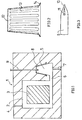
- Fig. 1 is generally a sand mold with a mold cavity 2 and a mold core 3 arranged in the mold cavity 2.
- the mold cavity 2 is connected to a ventilation duct 4.
- Reference numeral 5 denotes a feed chamber forming a reservoir for cast material, which communicates with the mold cavity 2 at 6.
- a filling channel 7 opens into the feeder chamber 5, via which the feeder chamber 5 and the mold cavity 2 can be filled with casting material from below using pressure.
- sealing element 8 is a cup-shaped, conical in the embodiment shown Designated sealing element, which an upper part of the surrounding by molding sand Seal chamber 5 seals.
- the sealing element described in more detail with reference to FIG. 2 consists of an aluminum foil in the embodiment shown and is in the deep-drawing process manufactured.
- a pipe lance 9 is pierced into the mold, the tip of which is the sealing element 8 has penetrated and has penetrated into the pantry 5.
- the pipe lance 9 has a cutting edge 10 at its tip, for their manufacture by axial end incisions formed tube wall legs with formation side openings 11 have been compressed.
- FIG. 2 where with the reference numeral 12 a weak point in the bottom wall of the cup-shaped sealing element 8, which indicates the penetration the pipe lance 9 in the pantry 5 facilitated.
- the sealing element points at its opening edge a circumferential collar 14.
- the sealing element can also include air holes, e.g. in Perforated shape.
- the pantry 5 and the mold cavity 2 is filled via the filling line 7 with casting material, the casting material is each supplied under a pressure that is equal to the material already filled in generated gravity at least compensates. If necessary, existing ventilation holes in the sealing element become clogged by the melt.
- the pipe lance 9 is connected to a pressure source via which of the pantry 5 exiting from the side openings 11 into the pantry Compressed air is supplied.
- the air pressure is at least equal to the gravity pressure of the still liquid casting material at the boundary formed in the pantry 5 between Compressed air and casting material.
- connection 6 which has a relatively large flow cross-section
- Cast material supplied from the pantry, being secured by air pressure is that this shrinkage compensation also affects that above the pantry located volume of the mold cavity extends. With sinking casting material level in the feed chamber 5 increases the pressure required for this.
- the sealing element 8 ensures that that which is required in each case in the feeder chamber 5 Pressure is maintained and there is no pressure drop due to escape of compressed air in the surrounding, not gas-tight molding sand.
- the sealing element 8 is so stable in the rest that it with the help of the insertion of cores Usually used devices can be used in the mold.
Landscapes
- Engineering & Computer Science (AREA)
- Mechanical Engineering (AREA)
- Casting Devices For Molds (AREA)
Applications Claiming Priority (2)
| Application Number | Priority Date | Filing Date | Title |
|---|---|---|---|
| DE19922534 | 1999-05-11 | ||
| DE1999122534 DE19922534A1 (de) | 1999-05-11 | 1999-05-11 | Gießform mit druckbeaufschlagbarer Speiserkammer |
Publications (2)
| Publication Number | Publication Date |
|---|---|
| EP1052041A2 true EP1052041A2 (fr) | 2000-11-15 |
| EP1052041A3 EP1052041A3 (fr) | 2003-12-17 |
Family
ID=7908252
Family Applications (1)
| Application Number | Title | Priority Date | Filing Date |
|---|---|---|---|
| EP00109888A Withdrawn EP1052041A3 (fr) | 1999-05-11 | 2000-05-10 | Moule avec masselotte sous pression |
Country Status (2)
| Country | Link |
|---|---|
| EP (1) | EP1052041A3 (fr) |
| DE (1) | DE19922534A1 (fr) |
Cited By (1)
| Publication number | Priority date | Publication date | Assignee | Title |
|---|---|---|---|---|
| US7601431B2 (en) | 2005-11-21 | 2009-10-13 | General Electric Company | Process for coating articles and articles made therefrom |
Family Cites Families (2)
| Publication number | Priority date | Publication date | Assignee | Title |
|---|---|---|---|---|
| US2568428A (en) * | 1949-09-09 | 1951-09-18 | Irvin A Billiar | Mold with riser and exothermic insert |
| US3513904A (en) * | 1967-10-26 | 1970-05-26 | Wyman Curtis Lane | Self-pressurizing feeder head device |
-
1999
- 1999-05-11 DE DE1999122534 patent/DE19922534A1/de not_active Withdrawn
-
2000
- 2000-05-10 EP EP00109888A patent/EP1052041A3/fr not_active Withdrawn
Cited By (1)
| Publication number | Priority date | Publication date | Assignee | Title |
|---|---|---|---|---|
| US7601431B2 (en) | 2005-11-21 | 2009-10-13 | General Electric Company | Process for coating articles and articles made therefrom |
Also Published As
| Publication number | Publication date |
|---|---|
| DE19922534A1 (de) | 2000-11-16 |
| EP1052041A3 (fr) | 2003-12-17 |
Similar Documents
| Publication | Publication Date | Title |
|---|---|---|
| DE10014591C1 (de) | Verfahren zum steigenden Gießen in Sandformen mit gerichteter Erstarrung von Gußteilen | |
| DE60111190T2 (de) | Verfahren und vorrichtung zur herstellung von gegossenen schaumkörpern | |
| EP1345716B1 (fr) | Masselotte presentant un corps tubulaire | |
| DE102006055988A1 (de) | Speisereinsatz und Speiserelement | |
| DE8110973U1 (de) | Geschlossener speisereinsatz | |
| DE20112425U1 (de) | Speisereinsatz mit metallischem Speiserfuß | |
| DE69324537T2 (de) | Metallguss unter Verwendung einer mit Speisern versehenen Form | |
| DE102015202709A1 (de) | Verwendung eines Speisereinsatzes und Verfahren zum Herstellen einer Gießform mit vertikaler Formteilung | |
| DE2802103A1 (de) | Verfahren zum giessen mittels einer vakuumgeformten kokille sowie kokille hierfuer | |
| DE1267801B (de) | Begasungsvorrichtung fuer die Kokille einer Niederdruckgiessanlage | |
| DE19922534A1 (de) | Gießform mit druckbeaufschlagbarer Speiserkammer | |
| DE602006001000T2 (de) | Verfahren und form für die herstellung von hotmelt-tintenpellets | |
| DE69809720T2 (de) | Verfahren, druckversorgungselement und druckversorgungssystem zum aktiven versorgung von gussstücken | |
| EP3727723A1 (fr) | Procédé de production d'une partie de moule ainsi qu'insert d'alimentation destiné à être utilisé dans un tel procédé | |
| DE10142357B4 (de) | Speiser mit einem rohrähnlichen Körper | |
| DE102011008082A1 (de) | Gussvorrichtung und Verfahren zur Herstellung zum Ein-,An- und/oder Umgießen eines faserverstärkten Kunststoffbauteils mit einer Leichtmetallschmelze | |
| DE10210681A1 (de) | Gießverfahren und Gießform mit exothermem Material | |
| DD265994A3 (de) | Druckgiessverfahren | |
| WO2024007045A1 (fr) | Dispositif de transport de matière fondue, ainsi que dispositif de transport de matière fondue équipé de la lance et procédé de fabrication d'une lance pour le dispositif de transport de matière fondue | |
| DE3872873T2 (de) | Giesserei-anschnitt-system. | |
| CH442628A (de) | Verfahren zur Herstellung von Gusstücken und verlorenes Modell zu dessen Ausführung | |
| EP3593923B1 (fr) | Procédé de coulée en continu, en particulier dans une installation de coulée verticale permettant de couler de l'acier | |
| EP3695917B1 (fr) | Insert de masselotte, procédé de fabrication d'un corps de masselotte pour un insert de masselotte ainsi que pièce maîtresse et boîte à noyaux destinés à la fabrication d'un corps de masselotte | |
| EP1556224B1 (fr) | Cartouche d'encre a mettre en place sur une tete d'impression | |
| EP3368234B1 (fr) | Mandrin de formage doté d'une enveloppe pouvant être élargie et modèle de coulée doté d'un mandrin de formage ainsi que procédé de coulée de métaux |
Legal Events
| Date | Code | Title | Description |
|---|---|---|---|
| PUAI | Public reference made under article 153(3) epc to a published international application that has entered the european phase |
Free format text: ORIGINAL CODE: 0009012 |
|
| AK | Designated contracting states |
Kind code of ref document: A2 Designated state(s): AT BE CH CY DE DK ES FI FR GB GR IE IT LI LU MC NL PT SE |
|
| AX | Request for extension of the european patent |
Free format text: AL;LT;LV;MK;RO;SI |
|
| RIN1 | Information on inventor provided before grant (corrected) |
Inventor name: LELLIG, KLAUS DR. Inventor name: BARSCHKETT, DIRK |
|
| RIN1 | Information on inventor provided before grant (corrected) |
Inventor name: LELLIG, KLAUS DR. Inventor name: BARSCHKETT, DIRK |
|
| RAP1 | Party data changed (applicant data changed or rights of an application transferred) |
Owner name: DISA INDUSTRIES A/S Owner name: VAW ALUCAST GMBH |
|
| PUAL | Search report despatched |
Free format text: ORIGINAL CODE: 0009013 |
|
| AK | Designated contracting states |
Kind code of ref document: A3 Designated state(s): AT BE CH CY DE DK ES FI FR GB GR IE IT LI LU MC NL PT SE |
|
| AX | Request for extension of the european patent |
Extension state: AL LT LV MK RO SI |
|
| RIC1 | Information provided on ipc code assigned before grant |
Ipc: 7B 22D 27/13 B Ipc: 7B 22C 9/08 B Ipc: 7B 22C 3/00 A |
|
| AKX | Designation fees paid | ||
| REG | Reference to a national code |
Ref country code: DE Ref legal event code: 8566 |
|
| STAA | Information on the status of an ep patent application or granted ep patent |
Free format text: STATUS: THE APPLICATION IS DEEMED TO BE WITHDRAWN |
|
| 18D | Application deemed to be withdrawn |
Effective date: 20040618 |