EP1052119A1 - Procédé pour déterminer la position des roues dans un système de surveillance de pression des pneumatiques d'un véhicule - Google Patents
Procédé pour déterminer la position des roues dans un système de surveillance de pression des pneumatiques d'un véhicule Download PDFInfo
- Publication number
- EP1052119A1 EP1052119A1 EP00109579A EP00109579A EP1052119A1 EP 1052119 A1 EP1052119 A1 EP 1052119A1 EP 00109579 A EP00109579 A EP 00109579A EP 00109579 A EP00109579 A EP 00109579A EP 1052119 A1 EP1052119 A1 EP 1052119A1
- Authority
- EP
- European Patent Office
- Prior art keywords
- wheel
- tire pressure
- pressure control
- time
- frequency signal
- Prior art date
- Legal status (The legal status is an assumption and is not a legal conclusion. Google has not performed a legal analysis and makes no representation as to the accuracy of the status listed.)
- Granted
Links
Images

Classifications
-
- B—PERFORMING OPERATIONS; TRANSPORTING
- B60—VEHICLES IN GENERAL
- B60C—VEHICLE TYRES; TYRE INFLATION; TYRE CHANGING; CONNECTING VALVES TO INFLATABLE ELASTIC BODIES IN GENERAL; DEVICES OR ARRANGEMENTS RELATED TO TYRES
- B60C23/00—Devices for measuring, signalling, controlling, or distributing tyre pressure or temperature, specially adapted for mounting on vehicles; Arrangement of tyre inflating devices on vehicles, e.g. of pumps or of tanks; Tyre cooling arrangements
- B60C23/02—Signalling devices actuated by tyre pressure
- B60C23/04—Signalling devices actuated by tyre pressure mounted on the wheel or tyre
- B60C23/0408—Signalling devices actuated by tyre pressure mounted on the wheel or tyre transmitting the signals by non-mechanical means from the wheel or tyre to a vehicle body mounted receiver
- B60C23/0415—Automatically identifying wheel mounted units, e.g. after replacement or exchange of wheels
- B60C23/0416—Automatically identifying wheel mounted units, e.g. after replacement or exchange of wheels allocating a corresponding wheel position on vehicle, e.g. front/left or rear/right
Definitions
- the invention relates to a method for performing the assignment of Tire pressure control devices for wheel positions in one Tire pressure control system of a motor vehicle according to the preamble of Claim 1.
- Tire pressure monitoring systems have been developed that associate one with each wheel Tire pressure control device included, the tire pressure of the Automobile tires measure automatically and at least a critical one Report any deviation from a target tire pressure to the motor vehicle driver.
- the Tire pressure monitoring devices can e.g. B. vulcanized into the tire or be glued or attached to or in the valve or on or in the rim his. Appropriate training is known.
- a tire pressure control system is known in which a tire pressure control device for each tire of the motor vehicle assigned.
- Each tire pressure control device communicates at regular intervals Intervals a measured pressure signal together with an individual ID to a central unit.
- value pairs are the Shape (identifier of the tire pressure monitoring device / wheel position) for each wheel of the motor vehicle stored so that by appropriate comparison in the Central unit can be deduced which identifier with the associated pressure signal from which wheel position of the motor vehicle is sent.
- a deviation of the transmitted pressure signal from one The motor vehicle driver is given a predetermined value at a wheel position by the Central unit displayed so that it can take appropriate action.
- each tire pressure control device is assigned a rotation sensor which is switched on for a first time interval. During the first time interval, a first defined angular position of the wheel to which the rotation sensor is assigned is determined from the signal of the rotation sensor. The tire control device transmits the individual identifier to the central unit at a first point in time t 1 at which the wheel assumes this first defined angular position.
- the same revolution sensor is later switched on for a second time interval, while the signal defines the same defined angular position of the wheel as in the first time interval.
- the tire pressure control device transmits its individual identifier to the central unit at a second point in time t 2 , in which the wheel assumes this defined angular position, the central unit knowing that the wheel from which the individual identifier was transmitted, between the points in time t 1 and t 2 has made an integer number of revolutions.
- the central unit now checks which speed sensor (the speed sensors are fixed sensors of a slip control system) or which wheel position transmitted an integer number of revolutions between times t 1 and t 2 .
- the corresponding wheel position is assigned in the central unit to the individual identifier transmitted by the tire pressure control device.
- the remaining tire pressure monitoring devices of the motor vehicle are assigned to their wheel position in the same way.
- the method known from DE 197 34 323 is a reliable one Assignment of tire pressure control devices to the wheel positions in one Tire pressure control system of a motor vehicle possible.
- tire pressure monitoring system needed in everyone Tire pressure control device a rotation sensor, which reduces the cost of Systems drives up.
- the rotation sensors strain the batteries of the tire pressure monitoring devices, although they are only during short time intervals can be switched on. This shortens the Battery life, so that the desired high battery life only is difficult to implement.
- a new mapping is done by changing the intensity of each Tire pressure monitoring devices sent signals from receivers, from one of which is permanently assigned to a wheel position, is measured and each signal from a tire pressure control device Wheel position is assigned at which it generates the highest signal intensity (For example, the signal intensity of the tire pressure control device, the located in the tire on the left front, the largest on the receiver, the the wheel position is assigned to the front left, so that a corresponding Assignment can be determined).
- the corresponding assignments will be stored in the central unit.
- the invention has for its object a method for performing the Assignment of tire pressure control devices to wheel positions in one To create tire pressure control system of a motor vehicle that deals with a can carry out inexpensive tire pressure control system.
- Extended high-frequency signal Each tire pressure monitoring device transmits its data, in particular its individual identifier and the pressure signal, in the form of high-frequency signals.
- An extended high-frequency signal is understood to mean a high-frequency signal that is considerably longer (that is at least an order of magnitude longer), than the high-frequency signals usually emitted by a tire pressure monitoring device.
- each extended radio frequency signal from the Tire pressure control device emitted with constant maximum amplitude, the result of the rotation of the wheel from which the elongated High frequency signal is sent, one of the rotation angle of the wheel or time-dependent individual course, as it does in Claim 2 is claimed.
- the invention takes advantage of the observation that the constant Maximum amplitude of a transmitted radio frequency signal due to the rotation of the wheel depends on the angle of rotation of the wheel or on the time gets individual course, so that based on the signal course to a relative angular position of the wheel can be inferred.
- the individual course is likely due to the different geometric Conditions in the wheel arches of the motor vehicle and on the time Change the distance of a tire pressure control device to that Wheel housing, which it is guided past during rotation.
- each time interval is during which an extended radio frequency signal is sent from a wheel is at least so long that the wheel in the time interval at least one Turns.
- the advantage of this training is the fact that first and second transmitted by a tire pressure control device prolonged high-frequency signal inevitably the same in some areas have a temporal profile from which a matching angular position can be determined.
- the length is dependent on the specified number of revolutions at which the centrifugal force sensor generates a signal so that it is ensured that the wheel during the transmission of the extended radio frequency signal makes at least one complete revolution (the centrifugal force sensor creates this So signal at x revolutions per minute, so for the length of the prolonged high-frequency signals thus a time of at least 1 / x minutes given).
- the advantage of the training according to claim 5 is therein see the first and second from a tire pressure control device emitted high-frequency signal with certain areas match.
- the central transmitter preferably also sends information about the Length of the tire pressure control devices to send out extended high-frequency signal to this, as in claim 7 is claimed.
- One of the vehicle speed is preferred dependent length transmitted, which is dimensioned so that it is ensured that the extended radio frequency signals are at least so long that each wheel, from from which an extended radio frequency signal is sent, at least one Turns during the broadcast.
- Assignment procedure started by pressing a switch.
- the switch should preferably be operated by the driver.
- the advantage This further training is to be seen in the fact that the assignment procedure only then is carried out when necessary, e.g. B. after a tire change.
- each extended radio frequency signal is a separate signal that is associated with constant maximum amplitude is sent.
- the signals transmitted by the tire pressure monitoring devices frequency modulated and are transmitted with constant maximum amplitude, the individual identifier in the extended radio frequency signal is included.
- the first and second extended radio frequency signal the first and second time in which the wheel assumes a corresponding relative angular position
- Cross correlation is a common mathematical method (for more details see figure description).
- the advantage of this training is the fact that there is a match relative angular position in the extended radio frequency signal in a simple manner and can be found reliably.
- FIG. 1 shows a highly schematic representation of a motor vehicle with wheels 2a to 2d, which has a tire pressure control system.
- the tire pressure control system contains, inter alia, tire pressure control devices 4a to 4d, one of which is contained in the tire of the wheels 2a to 2d (e.g. in the tire rubber or in or on the valve), or one of which is associated with a tire, e.g. B. by appropriate positioning and attachment to the rim.
- the tire pressure control devices 4a to 4d have a transmitter, with the aid of which they can transmit data in the form of high-frequency signals to a receiver 6 without contact.
- the receiver 6 transmits the data received by the tire pressure monitoring devices 4a to 4d via the transmission path 8 to a central unit 10.
- the receiver 6 is designed as a receiving antenna, with the aid of which the central unit 10 receives the transmitted data.
- the tire pressure control system also contains speed sensors 12a to 12d, which are fastened to the motor vehicle and are each assigned to a fixed wheel 2a to 2d of the motor vehicle.
- Each speed sensor 12a to 12d is also connected to the central unit via a transmission path 14a to 14d.
- the central unit 10 can use the transmission path to assign the signal from a speed sensor 12a to 12d to a wheel position.
- the tire pressure monitoring devices 4a to 4d transmit each an individual identifier and print data to the central unit 10. There the transmitted print data are evaluated and specified Compare print data. Soak the transmitted print data via certain extent from the specified print data, this will be the Motor vehicle driver displayed by the central unit 10.
- each tire pressure control device 4a to 4d transmits each tire pressure control device 4a to 4d at time intervals in addition to the individual identifier and possibly the print data extended high-frequency signal to the central unit 10.
- the extended high-frequency signals and that of the speed sensors 12a to 12d signals transmitted to the central unit 10 are stored in the central unit 10 an assignment of the tire pressure control devices 4a to 4d to the Wheel positions performed. This is detailed with the following Figures explained.
- Each transmitted high-frequency signal is preferably so long that the corresponding wheel 2a to 2d from which it is sent out during the duration of the signal makes at least one revolution. For example thereby be largely ensured that in the Tire pressure control devices 4a to 4d have a length of time for the extended ones High-frequency signals is specified, which is selected so that already at low speeds of the motor vehicle each wheel 2a to 2d during this length makes at least one turn.
- everyone Tire pressure control device 4a to 4d via a centrifugal force sensor 16a to 16d have the above a predetermined number of revolutions of the wheel 2a to 2d generates a signal, with a tire pressure monitoring device extending one High-frequency signal with the specified length only sends if that Centrifugal force sensor signal is present.
- the length of the lengthened High-frequency signal so on the number of revolutions at which the centrifugal force sensor 16a to 16d generates a signal, tuned that the wheel 2a to 2d at least one revolution during the transmission of the extended High frequency signal makes.
- the tire pressure monitoring system may have a central one Transmitter 18 and each tire pressure control device via a (not drawn) recipient.
- the central transmitter 18 sends a signal to all air pressure control devices 4a to 4d, which is an extended one immediately after receiving the signal Transmit high-frequency signal to the central unit 10.
- the central transmitter information about the length of the extended Transmit radio frequency signal from the tire pressure monitoring devices 4a to 4d to be transmitted. The length is determined by the central transmitter 18 preferably depending on the speed of the motor vehicle specified that it is ensured that each wheel 2a to 2d of the motor vehicle at least during the transmission of the extended high-frequency signal makes one turn.
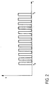
- FIG. 2 shows a diagram in which the signal generated by the speed sensors 12a to 12d is plotted over time.
- the speed sensors 12a to 12d can be sensors of a slip control system, for example, which are known per se and have a gear wheel disk with a certain number of teeth. With a full revolution of the motor vehicle wheel 2a to 2d, each tooth of the gear wheel of the corresponding speed sensor 12a to 12d generates a pulse, so that in the central unit 10 (see FIG. 1) the number of revolutions between the times is calculated from the number of pulses between two times can. In the diagram shown in FIG. 2, it was assumed, for example, that the gear disk has 6 teeth. Since the diagram has 12 signals between the times t 0 and t 1 , the motor vehicle wheel 2a to 2d has therefore made two revolutions between these times.
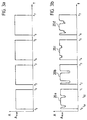
- FIG. 3a shows a diagram in which the magnitude of the amplitude of the extended high-frequency signals, which are generated by the tire pressure monitoring devices 4a to 4d, is plotted over time.
- the high frequency signal between the times t 0 and t 1 is from the tire pressure control device 4a
- the high frequency signal between the times t 2 and t 3 is from the tire pressure control device 4b
- the high frequency signal between the times t 4 and t 5 is from the tire pressure control device 4c
- the high frequency signal between times t 6 and t 7 is generated by the tire pressure control device 4d.
- the diagram shows that the amplitude amount of each generated high-frequency signal reaches the value A max over the entire length (in reality, the high-frequency signals are vibration signals, so that the maximum amplitude amount is reached twice during a vibration process; however, since it is is a high-frequency signal, the two maximum values are so close together during an oscillation period that only simplifies the envelope curve "of the amplitude was drawn.
- the time intervals between the times t 0 and t 1 or between t 2 and t 3 , t 4 and t 5 , t 6 and t 7 are so long that the corresponding motor vehicle wheel 2a to 2d , whose tire pressure control device has generated the extended high-frequency signal, has made at least one revolution in the time intervals mentioned.
- FIG. 3b shows a diagram in which the amplitude amount of the extended high-frequency signals received by the central unit 10 is plotted over time.
- the diagram shows that in the time interval from t 0 to t 1 of the tire pressure control device 4a, the central unit 10 receives a high-frequency signal with the profile 20a, in the time interval from t 2 to t 3 from the tire pressure control device 4b a high-frequency signal with the profile 20b, im Time interval from t 4 to t 5 receives a high-frequency signal with the curve 20c from the tire pressure control device 4c and a high-frequency signal with the curve 20d in the time interval from t 6 to t 7 .
- the received maximum amplitude of the high-frequency signal 20a largely has the maximum amount A max over the entire time interval from t 0 to t 1 .
- the central unit 10 receives a significantly reduced maximum amplitude only in the range of times t 01 and t 02 .
- Such a course of the amplitude received by the central unit 10 over time is due to the following:
- the tire pressure control device 4a rotates with the motor vehicle wheel 2a during the transmission of the extended high-frequency signal. As a result, the tire pressure control device 4a always takes a different position with respect to the wheel housing or to the ground contact surface of the wheel 2a.
- Interference in the transmitted radio-frequency signal or other effects means that the amplitude of the radio-frequency signal no longer reaches the same maximum value in the entire time interval, but changes in certain relative angular positions of the tire pressure control device 4a. A change in the transmitted amplitude always takes place in the same angular position of the tire pressure control device 4a.
- the central unit 10 thus receives an extended high-frequency signal 20a from the tire pressure control device 4a, which has an individual profile that is dependent on the angle of rotation of the wheel and on time.
- the other high-frequency signals 20b, 20c and 20d also have an individual profile that is dependent on the angle of rotation of the corresponding wheel and on time.
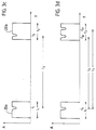
- the tire pressure control device 4a is assigned to the corresponding wheel position in which it is located: First, the tire pressure control device 4a sends its individual identifier to the central unit 10 Tire pressure control device 4a transmits a first extended high-frequency signal 20a to the central unit 10, which lasts for a first time interval I 1 . As a result of the rotation of the wheel, the extended high-frequency signal 20a has an individual profile which is dependent on the angle of rotation of the wheel or on the time, so that the high-frequency signal shown in FIG. 3c is received by the central unit 10.
- both extended high-frequency signals certainly have the reduction in the amplitude of the high-frequency signal explained in connection with FIGS. 3a and 3b, namely the first extended high-frequency signal 20a at the first time t 1 and the second extended high-frequency signal 20a at the second time t 2 .
- the wheel 2a which is associated with the tire pressure control device 4a, has made an integer number of revolutions in the third time interval I 3 from t 1 to t 2 .
- the central unit 10 now evaluates how many signals in the time interval I 3 have been transmitted to the speed sensors 12a to 12d via the transmission paths 14a to 14d.
- the number of transmitted signals is then used to calculate how many revolutions the wheels 2a to 2d assigned to the speed sensors 12a to 12d have made in the time interval I 3 .
- the individual identifier transmitted by the tire pressure control device 4a is assigned to that wheel position in which the wheel has made an integral number of revolutions in the time interval I 3 .
- the following number of revolutions is calculated in the central unit, if it is assumed that the toothed disc of the speed sensors has 6 teeth: number of revolutions of the wheel 2a - 100.1; Number of revolutions of the wheel 2b - 100.5; Number of revolutions of the wheel 2c - 100.5; Number of revolutions of the wheel 2d - 100.3.
- the wheel 2a has in the wheel position in the time interval I 3 front right "is made an integer number of revolutions.
- the remaining tire pressure control devices 4b to 4d are assigned to the wheel positions in the same way.
- Figure 3d shows largely the same diagram as Figure 3c.
- the only difference can be seen in the fact that in the interval I 2 a reduction in the amplitude of the extended high-frequency signal occurs twice, the corresponding motor vehicle wheel in the interval I 2 , which is as long as the interval I 1 , the corresponding angular position in which the reduction takes place, takes twice.
- Such a case constellation can occur, for example, in that the motor vehicle wheel rotates at a greater speed in the time interval I 2 than in the time interval I 1 .
- the time interval I 3 in which the corresponding motor vehicle wheel has made an integer number of revolutions can be selected either from t 1 to t 20 or from t 1 to t 21 and can be carried out accordingly as explained in connection with FIG. 3c .
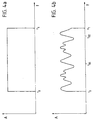
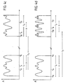
- FIG. 4a shows a diagram in which the magnitude of the amplitude of an extended high-frequency signal generated by the tire pressure control device 4a is plotted over time.
- the high frequency signal is sent from the tire control device 4a in the time interval from t 0 to t 1 .
- the diagram according to FIG. 4 is analogous to the diagram shown in FIG. 3a, so that reference is made to the corresponding description of the figures.
- FIG. 4b shows a diagram in which the amount of the amplitude received by the central unit 10 is plotted over time. Due to the rotation of the wheel and due to the changing angular position of the tire pressure control device 4a relative to the wheel housing, the central unit 10 receives an extended high-frequency signal, which has an individual profile that is dependent on the time or the angle of rotation of the wheel. Since the course of the high-frequency signal received by the central unit 10 depends on the angle of rotation of the wheel, it has a periodic course, the length of the period being determined by the duration of one revolution of the motor vehicle wheel.
- the tire pressure control device 4a first transmits its individual identifier at any point in time and immediately thereafter a first extended high-frequency signal that persists over a first time interval I 1 .
- the central unit 10 receives the individual identifier and the first extended high-frequency signal shown on the left in FIG. 4c.
- the same tire pressure control device 4a sends its individual identifier and immediately thereafter a second extended high-frequency signal that persists over a second time interval I 2 to the central unit 10.
- the central unit 10 receives the second extended high-frequency signal shown on the right in FIG. 4a.
- the two time intervals I 1 , I 2 are at least so long that the wheel 2a, from which the extended high-frequency signals are transmitted, makes at least one revolution in this time interval.
- the two time intervals I 1 and I 2 are preferably of the same length.
- the two received extended high-frequency signals are pushed one above the other in such a way that there is maximum overlap of these signals.
- the maximum overlap area X extends from time t 10 to time t 11 in the first time interval I 1 and from time t 20 to time t 21 in time interval I 2 .
- the wheel 2a In the two overlap areas, the wheel 2a, from which the extended high-frequency signal was transmitted, takes the same angular position at corresponding times. For example, at time t 10, the wheel 2a assumes the same angular position as at time t 20 and at time t 11 the same angular position as at time t 21 . The same applies to all times between times t 10 and t 11 or t 20 and t 21 if the time between times t 20 and t 21 is at the same distance from t 20 as that between times t 10 and Time at t 11 at time t 10 .
- the wheel 2a from which the extended high-frequency signal was emitted, makes an integer number of revolutions between two appropriately selected points in time, that is to say for example between the points in time t 10 and t 20 (ie in the time interval I 3 ).
- the central unit 10 With the aid of the speed sensors 12a to 12d, the central unit 10 now checks which wheel of the motor vehicle has made an integral number of revolutions in the time interval I 3 . This takes place, as has already been explained in connection with FIG. 3, so that reference is made to the corresponding statements at this point.
- the individual identifier transmitted by the tire pressure control device 4a becomes the corresponding wheel position (in the example front right ").
- the remaining tire pressure monitoring devices 4b to 4d are assigned to their wheel positions in the same way.
- the central unit 10 determines that the wheel is in the overlap area X has taken the same angular position between times t 10 and t 11 or between times t 20 and t 21 corresponding to one another, for example the same angular position is taken at times t 10 and t 20 or t 11 and t 21 . The same applies to those between times t 10 and t 11 or t 20 and t 21 lying times.
- the wheel 2a has the same angular position at the times t a and t b , since the time t a from the time t 10 has the same relative distance as the time t b from the time t 20 .
Landscapes
- Engineering & Computer Science (AREA)
- Mechanical Engineering (AREA)
- Measuring Fluid Pressure (AREA)
Applications Claiming Priority (2)
| Application Number | Priority Date | Filing Date | Title |
|---|---|---|---|
| DE19921413A DE19921413C1 (de) | 1999-05-08 | 1999-05-08 | Verfahren zur Durchführung der Zuordnung von Reifendruckkontrollvorrichtungen zu Radpositionen in einem Reifendruckkontrollsystem eines Kraftfahrzeuges |
| DE19921413 | 1999-05-08 |
Publications (2)
| Publication Number | Publication Date |
|---|---|
| EP1052119A1 true EP1052119A1 (fr) | 2000-11-15 |
| EP1052119B1 EP1052119B1 (fr) | 2002-10-09 |
Family
ID=7907519
Family Applications (1)
| Application Number | Title | Priority Date | Filing Date |
|---|---|---|---|
| EP00109579A Expired - Lifetime EP1052119B1 (fr) | 1999-05-08 | 2000-05-05 | Procédé pour déterminer la position des roues dans un système de surveillance de pression des pneumatiques d'un véhicule |
Country Status (2)
| Country | Link |
|---|---|
| EP (1) | EP1052119B1 (fr) |
| DE (2) | DE19921413C1 (fr) |
Cited By (18)
| Publication number | Priority date | Publication date | Assignee | Title |
|---|---|---|---|---|
| EP1214208A1 (fr) * | 1999-08-16 | 2002-06-19 | The Goodyear Tire & Rubber Company | Procede et systeme pour surveiller un etat dynamique d'un element rotatif, notamment d'un pneumatique |
| WO2002057097A3 (fr) * | 2001-01-17 | 2002-12-19 | Microchip Tech Inc | Procede et appareil permettant de mesurer la pression de gonflage des pneumatiques et de localiser les pneumatiques |
| US6571617B2 (en) | 2001-01-17 | 2003-06-03 | Microchip Technology Incorporated | Method and apparatus using directional antenna or learning modes for tire inflation pressure monitoring and location determination |
| FR2833523A1 (fr) * | 2001-12-18 | 2003-06-20 | Johnson Contr Automotive Elect | Systeme de controle de la pression des pneumatiques des roues d'un vehicule |
| EP1319531A3 (fr) * | 2001-12-12 | 2003-11-19 | Pacific Industrial Co., Ltd. | Appareil et méthode pour la surveillance de l'état des pneumatiques |
| FR2844748A1 (fr) * | 2002-09-25 | 2004-03-26 | Johnson Contr Automotive Elect | Systeme de controle de la pression des pneumatiques des roues d'un vehicule automobile |
| EP1616723A1 (fr) * | 2004-07-15 | 2006-01-18 | Nissan Motor Co., Ltd. | Système de contrôle de la pression de l'air de pneumatiques |
| DE102004053696A1 (de) * | 2004-11-06 | 2006-05-11 | Leopold Kostal Gmbh & Co. Kg | Reifendruckkontrollsystem für ein Kraftfahrzeug |
| US7116213B2 (en) | 2002-11-22 | 2006-10-03 | Michelin Recherche Et Technique S.A. | Acoustic wave device with modulation functionality |
| US8151127B2 (en) | 2000-07-26 | 2012-04-03 | Bridgestone Americas Tire Operations, Llc | System for conserving battery life in a battery operated device |
| US8266465B2 (en) | 2000-07-26 | 2012-09-11 | Bridgestone Americas Tire Operation, LLC | System for conserving battery life in a battery operated device |
| CN102686417A (zh) * | 2009-10-14 | 2012-09-19 | 感应动力有限公司 | 测量和分析轮胎气压并分配车轮位置的方法以及轮胎气压测量系统 |
| WO2013135628A1 (fr) * | 2012-03-16 | 2013-09-19 | Continental Automotive Gmbh | Dispositif et procédé pour la détermination d'une position angulaire absolue d'une roue d'un véhicule |
| EP2810797A1 (fr) * | 2013-06-03 | 2014-12-10 | Kabushiki Kaisha Tokai Rika Denki Seisakusho | Système de détermination de position de pneu |
| CN105658451A (zh) * | 2013-10-15 | 2016-06-08 | 大陆汽车有限公司 | 用于定位机动车中的轮的安装位置的方法和装置 |
| DE102015115731A1 (de) | 2015-09-17 | 2017-03-23 | Huf Hülsbeck & Fürst Gmbh & Co. Kg | Verfahren zur Zuordnung von Reifendruckkontrollvorrichtungen zu Radpositionen eines Fahrzeuges |
| CN110290946A (zh) * | 2016-12-22 | 2019-09-27 | 法国大陆汽车公司 | 用于配对安装在机动车辆车轮中的测量模块的方法和装置 |
| CN116323261A (zh) * | 2020-09-04 | 2023-06-23 | 大陆汽车科技有限公司 | 用于检测机动车辆的至少一个车轮的位置变化的方法 |
Families Citing this family (21)
| Publication number | Priority date | Publication date | Assignee | Title |
|---|---|---|---|---|
| DE10135936B4 (de) * | 2001-07-24 | 2005-01-05 | Siemens Ag | Einrichtung für das Überwachen mindestens eines Parameters für mehrere Fahrzeugräder |
| DE10144360B4 (de) | 2001-09-10 | 2018-12-27 | Continental Automotive Gmbh | Verfahren zum Zuordnen von Reifendruckmessvorrichtungen eines Kraftfahrzeugs zu Radpositionen und Vorrichtung zum Messen des Reifendrucks |
| DE10144359A1 (de) | 2001-09-10 | 2003-04-03 | Siemens Ag | Vorrichtung zum Messen des Reifendrucks eines jeden Rades eines Kraftfahrzeug und Verfahren zum Betreiben der Vorrichtung |
| US6693522B2 (en) * | 2001-10-12 | 2004-02-17 | Lear Corporation | System and method for tire pressure monitoring including automatic tire location recognition |
| DE10152338B4 (de) | 2001-10-24 | 2004-11-18 | Siemens Ag | Verfahren und System zur Überwachung der Räder eines Kraftfahrzeuges |
| DE10240159B3 (de) * | 2002-08-30 | 2004-07-15 | Nolex Ag | Reifenluftdruck-Kontrollvorrichtung |
| DE10259944A1 (de) | 2002-12-20 | 2004-07-01 | Continental Teves Ag & Co. Ohg | Verfahren zur automatischen Bestimmung der Einbaupositionen von Rädern in einem Kraftfahrzeug |
| DE10316074B4 (de) * | 2003-04-08 | 2006-01-26 | Global Dynamix Ag | Reifenluftdruck-Kontrollvorrichtung |
| DE10341785B4 (de) * | 2003-09-10 | 2006-04-27 | Global Dynamix Ag | Verfahren zur Zuordnung eines Radmoduls zu seiner Radposition und dafür geeignete Reifenluftdruck-Kontrollvorrichtung |
| DE10342297B4 (de) * | 2003-09-12 | 2014-08-21 | Continental Automotive Gmbh | Verfahren und Einrichtung zur Ermittlung der Radposition |
| DE102004040790A1 (de) * | 2004-08-23 | 2006-03-16 | Global Dynamix Ag | Vorrichtung und Verfahren zur Reifenluftdruckkontrolle |
| DE102005004833A1 (de) | 2005-02-02 | 2006-08-10 | Global Dynamix Ag | Reifenluftdruck-Kontrolleinrichtung und Verfahren zur Reifenluftdruckkontrolle |
| DE102005004825B4 (de) * | 2005-02-02 | 2007-06-06 | Global Dynamix Ag | Radmodul, Reifenluftdruck-Kontrolleinrichtung und Verfahren zur Reifenluftdruckkontrolle |
| DE102005018107B3 (de) * | 2005-04-19 | 2006-10-12 | Siemens Ag | Verfahren zur Bestimmung der Drehrichtung von rotierenden Körpern |
| DE102005026974A1 (de) | 2005-06-10 | 2007-01-04 | Global Dynamix Ag | Verfahren und System zur Bestimmung einer Radposition von Rädern an einem Fahrzeug |
| DE102009059788B4 (de) * | 2009-12-21 | 2014-03-13 | Continental Automotive Gmbh | Verfahren und Vorrichtung zum Lokalisieren der Verbaupositionen von Fahrzeugrädern in einem Kraftfahrzeug |
| DE102010021570A1 (de) | 2010-05-26 | 2011-12-01 | Gm Global Technology Operations Llc (N.D.Ges.D. Staates Delaware) | Verfahren zur Zuordnung von Reifendrucksensoren eines Reifendruckkontrollsystem zu Radpositionen |
| FR2969962B1 (fr) | 2010-12-30 | 2013-02-08 | Continental Automotive France | Procede de determination d'un angle de pivotement d'unite roue montee sur une valve de gonflage de type "snap-in" |
| FR2974033B1 (fr) | 2011-04-14 | 2013-05-10 | Continental Automotive France | Procede de localisation de la position de roues d'un vehicule |
| KR101351920B1 (ko) | 2012-08-21 | 2014-01-20 | 현대모비스 주식회사 | 타이어 압력 모니터링 장치 및 방법 |
| DE102020106754B4 (de) * | 2020-03-12 | 2025-04-17 | Zf Cv Systems Global Gmbh | Verfahren zur automatischen Zuordnung von Reifendrucksensoren |
Citations (2)
| Publication number | Priority date | Publication date | Assignee | Title |
|---|---|---|---|---|
| DE4205911A1 (de) | 1992-02-26 | 1993-09-02 | Uwatec Ag | Kontrollvorrichtung fuer den luftdruck von luftbereiften fahrzeugraedern |
| EP0895879A2 (fr) * | 1997-08-08 | 1999-02-10 | Continental Aktiengesellschaft | Procédé pour déterminer la position des roues dans un système de surveillance de pression des pneumatiques |
-
1999
- 1999-05-08 DE DE19921413A patent/DE19921413C1/de not_active Expired - Fee Related
-
2000
- 2000-05-05 EP EP00109579A patent/EP1052119B1/fr not_active Expired - Lifetime
- 2000-05-05 DE DE50000610T patent/DE50000610D1/de not_active Expired - Lifetime
Patent Citations (3)
| Publication number | Priority date | Publication date | Assignee | Title |
|---|---|---|---|---|
| DE4205911A1 (de) | 1992-02-26 | 1993-09-02 | Uwatec Ag | Kontrollvorrichtung fuer den luftdruck von luftbereiften fahrzeugraedern |
| EP0895879A2 (fr) * | 1997-08-08 | 1999-02-10 | Continental Aktiengesellschaft | Procédé pour déterminer la position des roues dans un système de surveillance de pression des pneumatiques |
| DE19734323A1 (de) | 1997-08-08 | 1999-02-11 | Continental Ag | Verfahren zur Durchführung der Zuordnung der Radposition zu Reifendruckkontrollvorrichtungen in einem Reifendruckkontrollsystem eines Kraftfahrzeugs |
Cited By (30)
| Publication number | Priority date | Publication date | Assignee | Title |
|---|---|---|---|---|
| EP1214208A1 (fr) * | 1999-08-16 | 2002-06-19 | The Goodyear Tire & Rubber Company | Procede et systeme pour surveiller un etat dynamique d'un element rotatif, notamment d'un pneumatique |
| US8151127B2 (en) | 2000-07-26 | 2012-04-03 | Bridgestone Americas Tire Operations, Llc | System for conserving battery life in a battery operated device |
| US8266465B2 (en) | 2000-07-26 | 2012-09-11 | Bridgestone Americas Tire Operation, LLC | System for conserving battery life in a battery operated device |
| WO2002057097A3 (fr) * | 2001-01-17 | 2002-12-19 | Microchip Tech Inc | Procede et appareil permettant de mesurer la pression de gonflage des pneumatiques et de localiser les pneumatiques |
| US6571617B2 (en) | 2001-01-17 | 2003-06-03 | Microchip Technology Incorporated | Method and apparatus using directional antenna or learning modes for tire inflation pressure monitoring and location determination |
| EP1319531A3 (fr) * | 2001-12-12 | 2003-11-19 | Pacific Industrial Co., Ltd. | Appareil et méthode pour la surveillance de l'état des pneumatiques |
| FR2833523A1 (fr) * | 2001-12-18 | 2003-06-20 | Johnson Contr Automotive Elect | Systeme de controle de la pression des pneumatiques des roues d'un vehicule |
| WO2003051652A1 (fr) * | 2001-12-18 | 2003-06-26 | Johnson Controls Automotive Electronics | Systeme de controle de la pression des pneumatiques des roues d'un vehicule |
| EP1403099A1 (fr) * | 2002-09-25 | 2004-03-31 | Johnson Controls Automotive Electronics | Système de contrôle de la pression des pneumatiques des roues d'un véhicule automobile |
| FR2844748A1 (fr) * | 2002-09-25 | 2004-03-26 | Johnson Contr Automotive Elect | Systeme de controle de la pression des pneumatiques des roues d'un vehicule automobile |
| US7116213B2 (en) | 2002-11-22 | 2006-10-03 | Michelin Recherche Et Technique S.A. | Acoustic wave device with modulation functionality |
| US7230525B2 (en) | 2004-07-15 | 2007-06-12 | Nissan Motor Co., Ltd. | Tire air pressure monitoring system |
| EP1616723A1 (fr) * | 2004-07-15 | 2006-01-18 | Nissan Motor Co., Ltd. | Système de contrôle de la pression de l'air de pneumatiques |
| DE102004053696A1 (de) * | 2004-11-06 | 2006-05-11 | Leopold Kostal Gmbh & Co. Kg | Reifendruckkontrollsystem für ein Kraftfahrzeug |
| WO2006048271A1 (fr) | 2004-11-06 | 2006-05-11 | Leopold Kostal Gmbh & Co. Kg | Systeme de verification de pression de pneumatiques pour vehicule automobile |
| CN100564079C (zh) * | 2004-11-06 | 2009-12-02 | 利奥波德·科世达责任有限股份公司 | 汽车的轮胎压力控制系统 |
| CN102686417A (zh) * | 2009-10-14 | 2012-09-19 | 感应动力有限公司 | 测量和分析轮胎气压并分配车轮位置的方法以及轮胎气压测量系统 |
| CN102686417B (zh) * | 2009-10-14 | 2016-02-03 | 玛克西姆综合公司 | 测量和分析轮胎气压并分配车轮位置的方法以及轮胎气压测量系统 |
| CN104303015A (zh) * | 2012-03-16 | 2015-01-21 | 大陆汽车有限公司 | 用于确定汽车车轮的绝对角度位置的装置和方法 |
| WO2013135628A1 (fr) * | 2012-03-16 | 2013-09-19 | Continental Automotive Gmbh | Dispositif et procédé pour la détermination d'une position angulaire absolue d'une roue d'un véhicule |
| US9701287B2 (en) | 2012-03-16 | 2017-07-11 | Continental Automotive Gmbh | Device and method for determining an absolute angular position of a wheel of a vehicle |
| EP2810797A1 (fr) * | 2013-06-03 | 2014-12-10 | Kabushiki Kaisha Tokai Rika Denki Seisakusho | Système de détermination de position de pneu |
| US9180742B2 (en) | 2013-06-03 | 2015-11-10 | Kabushiki Kaisha Tokai Rika Denki Seisakusho | Tire position determination system having tire pressure sensors and using axle rotation detectors |
| CN105658451A (zh) * | 2013-10-15 | 2016-06-08 | 大陆汽车有限公司 | 用于定位机动车中的轮的安装位置的方法和装置 |
| US10046608B2 (en) | 2013-10-15 | 2018-08-14 | Continental Automotive Gmbh | Method and arrangement for locating the installation position of wheels in a motor vehicle |
| DE102015115731A1 (de) | 2015-09-17 | 2017-03-23 | Huf Hülsbeck & Fürst Gmbh & Co. Kg | Verfahren zur Zuordnung von Reifendruckkontrollvorrichtungen zu Radpositionen eines Fahrzeuges |
| CN110290946A (zh) * | 2016-12-22 | 2019-09-27 | 法国大陆汽车公司 | 用于配对安装在机动车辆车轮中的测量模块的方法和装置 |
| CN110290946B (zh) * | 2016-12-22 | 2021-10-29 | 法国大陆汽车公司 | 用于配对安装在机动车辆车轮中的测量模块的方法和装置 |
| CN116323261A (zh) * | 2020-09-04 | 2023-06-23 | 大陆汽车科技有限公司 | 用于检测机动车辆的至少一个车轮的位置变化的方法 |
| CN116323261B (zh) * | 2020-09-04 | 2025-07-22 | 大陆汽车科技有限公司 | 用于检测机动车辆的至少一个车轮的位置变化的方法 |
Also Published As
| Publication number | Publication date |
|---|---|
| DE50000610D1 (de) | 2002-11-14 |
| DE19921413C1 (de) | 2000-11-23 |
| EP1052119B1 (fr) | 2002-10-09 |
Similar Documents
| Publication | Publication Date | Title |
|---|---|---|
| EP1052119B1 (fr) | Procédé pour déterminer la position des roues dans un système de surveillance de pression des pneumatiques d'un véhicule | |
| EP0806306B1 (fr) | Système de surveillance de pression des pneumatiques d'un véhicule automobile et procédé de son adjonction à la position d'un pneumatique | |
| DE19734323B4 (de) | Verfahren zur Durchführung der Zuordnung der Radposition zu Reifendruckkontrollvorrichtungen in einem Reifendruckkontrollsystem eines Kraftfahrzeugs | |
| DE10144360B4 (de) | Verfahren zum Zuordnen von Reifendruckmessvorrichtungen eines Kraftfahrzeugs zu Radpositionen und Vorrichtung zum Messen des Reifendrucks | |
| DE10247761B4 (de) | System und Verfahren zur Reifendrucküberwachung einschliesslich einer automatischen Reifenlagererkennung | |
| DE19534616B4 (de) | Reifendruck-Überwachungseinrichtung | |
| DE112013003908B4 (de) | Radpositionserfassungsvorrichtung und Reifenluftdruckerfassungsvorrichtung mit derselben | |
| DE112012005253B4 (de) | Radpositionsdetektor und Reifenfülldruckdetektor mit demselben | |
| EP1053114A1 (fr) | Procede pour faire fonctionner une unite servant a surveiller et a signaler sans fil une variation de pression dans des pneus de vehicules | |
| EP0806307B1 (fr) | Système de surveillance de pression des pneumatiques | |
| WO1998005518A1 (fr) | Procede pour le traitement des signaux d'un systeme de surveillance de la pression des pneus | |
| DE19849390C2 (de) | Verfahren zur Durchführung der Zuordnung von Luftdruckkontrollvorrichtungen zu Radpositionen in einem Luftdruckkontrollsystem eines Kraftfahrzeuges | |
| EP1059177A1 (fr) | Procédé pour déterminer la position des roues dans un système de surveillance de pression des pneumatiques d'un véhicule automobile | |
| DE112013000606T5 (de) | Radspositionsdetektor und Reifenfülldruckdetektor mit demselben | |
| DE10223214A1 (de) | Verfahren zum Zuordnen von Reifenmodulen zu Radpositionen eines Reifendrucküberwachungssytems für ein Kraftfahrzeug und Vorrichtung zum Überwachen des Reifendrucks | |
| DE10307265A1 (de) | System und Verfahren zur Reifendrucküberwachung mit automatischer Reifenpositionserkennung | |
| DE102013101681A1 (de) | Reifendruck-Erfassungsvorrichtung mit einer Lenkpositionserfassungsfunktion | |
| DE102010000919B4 (de) | Verfahren zur Reifenluftdruckmessung und -auswertung mit einer Zuordnung von Radpositionen sowie Reifenluftdruckmesssystem | |
| EP2648926B1 (fr) | Procédé de transmission radio chiffrée de données | |
| EP1807270B1 (fr) | Systeme de verification de pression de pneumatiques pour vehicule automobile | |
| DE102009015567A1 (de) | Vorrichtung und Verfahren zum Überwachen eines Fahrzeugzustands | |
| DE10152337A1 (de) | Verfahren und System zur Ermittlung von Radpositionen | |
| DE102020106754B4 (de) | Verfahren zur automatischen Zuordnung von Reifendrucksensoren | |
| DE10229465B4 (de) | Anordnung zur Überwachung wenigstens eines Parameters für mehrere Fahrzeugräder | |
| DE102006055878B4 (de) | Verfahren zum Zuordnen von Identifikationscodes in Funksignalen von Reifendruckkontrolleinrichtungen an Fahrzeugrädern zu deren Position und zum Durchführen des Verfahrens ausgestattetes Fahrzeug |
Legal Events
| Date | Code | Title | Description |
|---|---|---|---|
| PUAI | Public reference made under article 153(3) epc to a published international application that has entered the european phase |
Free format text: ORIGINAL CODE: 0009012 |
|
| AK | Designated contracting states |
Kind code of ref document: A1 Designated state(s): DE FR GB IT |
|
| AX | Request for extension of the european patent |
Free format text: AL;LT;LV;MK;RO;SI |
|
| 17P | Request for examination filed |
Effective date: 20010515 |
|
| AKX | Designation fees paid |
Free format text: DE FR GB IT |
|
| GRAG | Despatch of communication of intention to grant |
Free format text: ORIGINAL CODE: EPIDOS AGRA |
|
| GRAG | Despatch of communication of intention to grant |
Free format text: ORIGINAL CODE: EPIDOS AGRA |
|
| GRAH | Despatch of communication of intention to grant a patent |
Free format text: ORIGINAL CODE: EPIDOS IGRA |
|
| 17Q | First examination report despatched |
Effective date: 20020326 |
|
| GRAH | Despatch of communication of intention to grant a patent |
Free format text: ORIGINAL CODE: EPIDOS IGRA |
|
| GRAA | (expected) grant |
Free format text: ORIGINAL CODE: 0009210 |
|
| AK | Designated contracting states |
Kind code of ref document: B1 Designated state(s): DE FR GB IT |
|
| REG | Reference to a national code |
Ref country code: GB Ref legal event code: FG4D Free format text: NOT ENGLISH |
|
| REF | Corresponds to: |
Ref document number: 50000610 Country of ref document: DE Date of ref document: 20021114 |
|
| GBT | Gb: translation of ep patent filed (gb section 77(6)(a)/1977) |
Effective date: 20030206 |
|
| ET | Fr: translation filed | ||
| PLBE | No opposition filed within time limit |
Free format text: ORIGINAL CODE: 0009261 |
|
| STAA | Information on the status of an ep patent application or granted ep patent |
Free format text: STATUS: NO OPPOSITION FILED WITHIN TIME LIMIT |
|
| 26N | No opposition filed |
Effective date: 20030710 |
|
| PGFP | Annual fee paid to national office [announced via postgrant information from national office to epo] |
Ref country code: GB Payment date: 20140521 Year of fee payment: 15 |
|
| PGFP | Annual fee paid to national office [announced via postgrant information from national office to epo] |
Ref country code: FR Payment date: 20140527 Year of fee payment: 15 Ref country code: IT Payment date: 20140528 Year of fee payment: 15 |
|
| GBPC | Gb: european patent ceased through non-payment of renewal fee |
Effective date: 20150505 |
|
| PG25 | Lapsed in a contracting state [announced via postgrant information from national office to epo] |
Ref country code: IT Free format text: LAPSE BECAUSE OF NON-PAYMENT OF DUE FEES Effective date: 20150505 |
|
| REG | Reference to a national code |
Ref country code: FR Ref legal event code: ST Effective date: 20160129 |
|
| PG25 | Lapsed in a contracting state [announced via postgrant information from national office to epo] |
Ref country code: GB Free format text: LAPSE BECAUSE OF NON-PAYMENT OF DUE FEES Effective date: 20150505 |
|
| PG25 | Lapsed in a contracting state [announced via postgrant information from national office to epo] |
Ref country code: FR Free format text: LAPSE BECAUSE OF NON-PAYMENT OF DUE FEES Effective date: 20150601 |
|
| PGFP | Annual fee paid to national office [announced via postgrant information from national office to epo] |
Ref country code: DE Payment date: 20180531 Year of fee payment: 19 |
|
| REG | Reference to a national code |
Ref country code: DE Ref legal event code: R119 Ref document number: 50000610 Country of ref document: DE |
|
| PG25 | Lapsed in a contracting state [announced via postgrant information from national office to epo] |
Ref country code: DE Free format text: LAPSE BECAUSE OF NON-PAYMENT OF DUE FEES Effective date: 20191203 |