EP1052130A2 - Régulateur de pression d'embout de remplissage - Google Patents
Régulateur de pression d'embout de remplissage Download PDFInfo
- Publication number
- EP1052130A2 EP1052130A2 EP00303848A EP00303848A EP1052130A2 EP 1052130 A2 EP1052130 A2 EP 1052130A2 EP 00303848 A EP00303848 A EP 00303848A EP 00303848 A EP00303848 A EP 00303848A EP 1052130 A2 EP1052130 A2 EP 1052130A2
- Authority
- EP
- European Patent Office
- Prior art keywords
- fuel
- interior region
- fuel tank
- diaphragm
- delivery apparatus
- Prior art date
- Legal status (The legal status is an assumption and is not a legal conclusion. Google has not performed a legal analysis and makes no representation as to the accuracy of the status listed.)
- Withdrawn
Links
- 239000000945 filler Substances 0.000 title abstract description 7
- 239000000446 fuel Substances 0.000 claims abstract description 370
- 239000002828 fuel tank Substances 0.000 claims abstract description 141
- 238000004891 communication Methods 0.000 claims description 25
- 239000012530 fluid Substances 0.000 claims description 25
- 238000000034 method Methods 0.000 claims description 9
- 230000004044 response Effects 0.000 claims description 7
- 230000035807 sensation Effects 0.000 claims description 3
- 239000000203 mixture Substances 0.000 description 60
- 239000007788 liquid Substances 0.000 description 44
- 238000007789 sealing Methods 0.000 description 9
- 230000007246 mechanism Effects 0.000 description 7
- 238000013022 venting Methods 0.000 description 6
- 230000007423 decrease Effects 0.000 description 4
- 230000009467 reduction Effects 0.000 description 4
- 239000003795 chemical substances by application Substances 0.000 description 3
- 230000001105 regulatory effect Effects 0.000 description 3
- 230000004043 responsiveness Effects 0.000 description 3
- 238000001179 sorption measurement Methods 0.000 description 3
- 230000008859 change Effects 0.000 description 2
- 230000008569 process Effects 0.000 description 2
- 230000003134 recirculating effect Effects 0.000 description 2
- 230000003247 decreasing effect Effects 0.000 description 1
- 230000001419 dependent effect Effects 0.000 description 1
- 238000001514 detection method Methods 0.000 description 1
- 238000007599 discharging Methods 0.000 description 1
- 238000001704 evaporation Methods 0.000 description 1
- 230000008020 evaporation Effects 0.000 description 1
- 239000000463 material Substances 0.000 description 1
- 238000012986 modification Methods 0.000 description 1
- 230000004048 modification Effects 0.000 description 1
- 230000007935 neutral effect Effects 0.000 description 1
- 238000005192 partition Methods 0.000 description 1
Images


Classifications
-
- B—PERFORMING OPERATIONS; TRANSPORTING
- B60—VEHICLES IN GENERAL
- B60K—ARRANGEMENT OR MOUNTING OF PROPULSION UNITS OR OF TRANSMISSIONS IN VEHICLES; ARRANGEMENT OR MOUNTING OF PLURAL DIVERSE PRIME-MOVERS IN VEHICLES; AUXILIARY DRIVES FOR VEHICLES; INSTRUMENTATION OR DASHBOARDS FOR VEHICLES; ARRANGEMENTS IN CONNECTION WITH COOLING, AIR INTAKE, GAS EXHAUST OR FUEL SUPPLY OF PROPULSION UNITS IN VEHICLES
- B60K15/00—Arrangement in connection with fuel supply of combustion engines or other fuel consuming energy converters, e.g. fuel cells; Mounting or construction of fuel tanks
- B60K15/03—Fuel tanks
- B60K15/04—Tank inlets
-
- B—PERFORMING OPERATIONS; TRANSPORTING
- B60—VEHICLES IN GENERAL
- B60K—ARRANGEMENT OR MOUNTING OF PROPULSION UNITS OR OF TRANSMISSIONS IN VEHICLES; ARRANGEMENT OR MOUNTING OF PLURAL DIVERSE PRIME-MOVERS IN VEHICLES; AUXILIARY DRIVES FOR VEHICLES; INSTRUMENTATION OR DASHBOARDS FOR VEHICLES; ARRANGEMENTS IN CONNECTION WITH COOLING, AIR INTAKE, GAS EXHAUST OR FUEL SUPPLY OF PROPULSION UNITS IN VEHICLES
- B60K15/00—Arrangement in connection with fuel supply of combustion engines or other fuel consuming energy converters, e.g. fuel cells; Mounting or construction of fuel tanks
- B60K15/03—Fuel tanks
- B60K15/04—Tank inlets
- B60K2015/0458—Details of the tank inlet
- B60K2015/048—Arrangements for sealing the fuel inlet during filling
-
- Y—GENERAL TAGGING OF NEW TECHNOLOGICAL DEVELOPMENTS; GENERAL TAGGING OF CROSS-SECTIONAL TECHNOLOGIES SPANNING OVER SEVERAL SECTIONS OF THE IPC; TECHNICAL SUBJECTS COVERED BY FORMER USPC CROSS-REFERENCE ART COLLECTIONS [XRACs] AND DIGESTS
- Y10—TECHNICAL SUBJECTS COVERED BY FORMER USPC
- Y10T—TECHNICAL SUBJECTS COVERED BY FORMER US CLASSIFICATION
- Y10T137/00—Fluid handling
- Y10T137/8593—Systems
- Y10T137/86292—System with plural openings, one a gas vent or access opening
- Y10T137/86324—Tank with gas vent and inlet or outlet
Definitions
- This invention relates to vehicle fuel systems including a fuel tank and a fill cup for receiving liquid fuel. More particularly, this invention relates to a fuel vapor recirculation systems for communicating fuel vapor from the fuel tank to the fill cup.
- fuel vapor is generated in the fuel tank during operation of the vehicle, for example, by evaporation or by sloshing of the liquid fuel against the walls of the fuel tank. Excessive pressure can build up in the fuel tank as a result of the newly formed fuel vapor unless control devices are provided to vent the fuel vapor from the fuel tank. These control devices communicate the fuel vapor to a canister which contains adsorption agents that are intended to adsorb the fuel vapors.
- a fuel system including a fuel tank, a fuel vapor discharge apparatus coupled to the fuel tank, a fuel delivery apparatus coupled to the fuel tank, and a fuel vapor recirculation apparatus.
- the fuel tank is formed to include an interior region and the fuel vapor discharge apparatus vents fuel vapor from the interior region of the fuel tank.
- the fuel delivery apparatus is formed to include an interior region and delivers fuel to the interior region of the fuel tank.
- the fuel vapor recirculation apparatus is in fluid communication with the interior region of the fuel tank to deliver fuel vapor from the interior region of the fuel tank to the interior region of the fuel delivery apparatus.
- the fuel vapor recirculation apparatus includes a sensor, a housing, and a flow restrictor.
- the sensor is in fluid communication with the interior region of the fuel delivery apparatus to sense pressure extant in the interior region of the fuel delivery apparatus.
- the flow restrictor is coupled to the sensor and is positioned to lie in the housing to move between a first position restricting the flow of fuel vapor from the fuel tank to the fuel delivery apparatus in response to sensations from the sensor and a second position permitting flow of fuel vapor from the fuel tank to the fuel delivery apparatus in response to sensations from the sensor.
- a method for communicating fuel vapor from an interior region of a vehicle fuel tank to an interior region of a fuel delivery apparatus coupled to the vehicle fuel tank includes the steps of providing a conduit and a valve, sensing pressure, and moving the valve.
- the conduit defines a passage configured to communicate fuel vapor from an interior region of a fuel tank to an interior region of a fuel delivery apparatus.
- the valve is coupled to the conduit and includes a flow restrictor configured to move between a first position restricting the flow of fuel vapor through the passage and a second position permitting the flow of fuel vapor through the passage and a sensor coupled to the valve.
- the sensing step senses pressure extant in the interior region of the fuel delivery apparatus.
- the moving step moves the valve to the second position when pressure extant in the interior region of the fuel delivery apparatus is at a predetermined level.
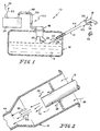
- FIG. 1 An illustration of a conventional fuel system 10 is shown in Fig. 1.
- Conventional fuel system 10 includes a fuel tank 12 for storage of liquid fuel 14, a fuel delivery apparatus 16 for delivering liquid fuel 14 to fuel tank 12 from a fuel dispensing nozzle 18, and a fuel vapor discharge apparatus 20 for discharging excess fuel vapor 22 from fuel tank 12.
- Fuel vapor discharge apparatus 20 includes a canister 24 that contains an adsorption agent (not shown) that adsorbs the fuel vapor 22 vented from fuel tank 12. As shown in Fig. 2, outside air 26 is introduced into conventional fuel system 10 through fuel delivery apparatus 16. Outside air 26 is difficult to pass through canister 24 and requires that the size of canister 24 be increased to compensate for the difficulty in passing outside air 26 through canister 24.
- an adsorption agent not shown
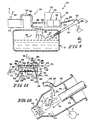
- a fuel system 28, according to the present disclosure reduces the amount of outside air 26 passed though a canister 30 and also decreases the amount of fuel vapor 22 processed by canister 30.
- fuel system 28 includes fuel tank 12, a fuel delivery apparatus 34, a fuel vapor discharge apparatus 36 including canister 30, and a fuel vapor recirculation apparatus 38 for recirculating fuel vapor 22 from fuel tank 12 to fuel delivery apparatus 34.
- canister 30 The size of canister 30 is reduced by reducing the volume of fuel vapor 22 and outside air 26 passed through canister 30.
- the volume of fuel vapor 22 passed through canister 30 is reduced by recirculating fuel vapor 22 from fuel tank 12 to fuel delivery apparatus 34. Recirculation reduces the volume of outside air 26 introduced to fuel system 28 by replacing outside air 26 with fuel vapor 22.
- Recirculation provides fuel vapor/air mixture 48 to fuel delivery apparatus 34 from fuel tank 12 that would otherwise be routed to canister 30 but now displaces a portion of outside air 26 that would otherwise be drawn into fuel system 28.
- Recirculation reduces the volume of fuel vapor 22 present in fuel system 28 that must be adsorbed by canister 30. Because fuel vapor 22 is recirculated back to fuel delivery apparatus 34, fuel vapor 22 has a second chance to condense into liquid fuel 14 in fuel tank 12 or in liquid fuel 14 being introduced to fuel system 28. Condensing reduces the volume of fuel vapor 22 by convening fuel vapor 22 into liquid fuel 14. Thus, because less fuel vapor 22 exists in fuel system 28, less fuel vapor 22 needs to be adsorbed by canister 30 of fuel system 28 and the size of canister 30 of fuel system 28 can be reduced in comparison to canister 24 of conventional fuel system 10.
- canister 30 according to the present disclosure operates more efficiently than canister 24 of conventional fuel system 10 because canister 24 of conventional fuel system 10 must process more efficiency-reducing outside air 26 than canister 30 must process.
- canister 30 of fuel system 28 according to the present disclosure is designed to be smaller than less efficiently operating canister 24 of conventional fuel system 10. By reducing the size of canister 30 through recirculation, labor and material costs can be reduced for fuel system 28 in comparison to conventional fuel system 10.
- Fuel delivery apparatus 16 of conventional fuel system 10 includes a fill cup 40 for accepting fuel dispensing nozzle 18 during refueling, a closure cap 42 for closing over and substantially sealing fill cup 40 after refueling, and a filler neck 44 coupled to fill cup 40 and fuel tank 12 for communicating liquid fuel 14 to fuel tank 12.
- a fill cup 40 for accepting fuel dispensing nozzle 18 during refueling
- a closure cap 42 for closing over and substantially sealing fill cup 40 after refueling
- a filler neck 44 coupled to fill cup 40 and fuel tank 12 for communicating liquid fuel 14 to fuel tank 12.
- liquid fuel 14 As liquid fuel 14 travels though fuel delivery apparatus 34 and fuel tank 12, liquid fuel 14 transforms from its liquid state to a vapor state into fuel vapor 22. Outside air 26 mixes with fuel vapor 22 to form fuel vapor/air mixture 48 within conventional fuel system 10. Fuel vapor/air mixture 48 must often be vented from fuel tank 12 to prevent excess build up of pressure in fuel tank 12 that impedes the flow of liquid fuel 14 into fuel tank 14 and can create potential structure-damaging pressure within conventional fuel system 10.
- Fuel vapor discharge apparatus 20 communicates fuel vapor/air mixture 48 from fuel tank 12, adsorbs a portion of fuel vapor 22 within fuel vapor/air mixture 48, and releases outside air 26 within fuel vapor/air mixture 48 and the remaining portion of fuel vapor 22 into the atmosphere.
- Fuel vapor discharge apparatus 20 includes an ORVR control valve 46 coupled to fuel tank 12 for regulating the flow of fuel vapor/air mixture 48 from fuel tank 12 and preventing the flow of liquid fuel 14 from fuel tank 12 in the event of vehicle roll-over.
- Fuel vapor discharge apparatus 20 of conventional fuel system 10 further includes canister 24 for adsorbing fuel vapor 22 and a fuel vapor discharge conduit 50 coupled to ORVR control value 46 and canister 24 for communicating fuel vapor/air mixture 48 from ORVR control valve 46 to canister 24.
- Fuel vapor discharge apparatus 36 of the present disclosure communicates fuel vapor/air mixture 48 from fuel tank 12, adsorbs a portion of fuel vapor 22 within fuel vapor/air mixture 48, and releases outside air 26 within fuel vapor/air mixture 48 and the remaining portion of fuel vapor 22 into the atmosphere.
- Fuel vapor discharge apparatus 20 includes ORVR control valve 46 coupled to fuel tank 12 for regulating the flow of fuel vapor/air mixture 48 from fuel tank 12 and preventing the flow of liquid fuel 14 from fuel tank 12 in the event of vehicle roll-over.
- Fuel vapor discharge apparatus 36 further includes canister 30 for adsorbing fuel vapor 22 and a fuel vapor discharge conduit 54 coupled to ORVR control value 46, and canister 30.
- Fuel delivery apparatus 34 of fuel system 28 includes a fill cup 52 for accepting fuel dispensing nozzle 18 during refueling, gas cap 42 for closing over and substantially sealing fill cup 52 after refueling, filler neck 44 coupled to fill cup 52 and fuel tank 12, and an interior region 83 defined by fill cup 52 and filler neck 44 for communicating liquid fuel 14 to fuel tank 12.
- Fill cup 52 is coupled to fuel vapor recirculation apparatus 38 and includes a sealing mechanism 45 that loosely receives fuel dispensing nozzle 18 during refueling.
- the introduction of liquid fuel 14 into fuel system 28 creates negative pressure within fill cup 52.
- the negative pressure created within fill cup 52 draws fuel vapor/air mixture 48 through fuel vapor recirculation apparatus 38 into and through fill cup 52 and outside air 26 past sealing mechanism 45.
- fuel vapor/air mixture 48 By drawing fuel vapor/air mixture 48 through recirculation apparatus 38, fuel vapor/air mixture 48 is recirculated from fuel tank 12 into fill cup 52. Fuel vapor/air mixture 48 is drawn from fuel tank 12 to fill cup 52 by the negative pressure created in fill cup 52 during refueling and is then entrained into the liquid fuel 14 back into fuel tank 12. This recirculation of fuel vapor/air mixture 48 reduces the volume of outside 26 drawn into fill cup 52. The recirculation of fuel vapor/air mixture 48 causes this reduction by displacing a portion of the outside air 26 normally drawn into fill cup 52 with recirculated fuel vapor/air mixture 48.
- fuel vapor 22 within fuel vapor/air mixture 48 has an additional chance to condense within liquid fuel 14, fuel tank 12, and the other components of fuel system 28.
- This condensing transforms fuel vapor 22 from its vapor state to a liquid state into liquid fuel 14.
- the overall volume of fuel vapor 22 and fuel vapor/air mixture 48 is reduced so that the condensed portion of the fuel vapor/air mixture 48 need not be vented from fuel tank 12 of fuel system 28. Therefore, less fuel vapor/air mixture 48 needs to vented from fuel system 28 to prevent excess build up of pressure in fuel tank 12 that impedes the flow of liquid fuel 14 into fuel tank 12 and creates potential structural damaging pressure within fuel system 28.
- Fuel vapor recirculation apparatus 38 includes a fuel vapor recirculation conduit 56 for communicating fuel vapor/air mixture 48, a pressure sensor 58 for detecting pressure levels in fill cup 52, and a flow restrictor 60 for regulating the flow of fuel vapor/air mixture 48 though fuel vapor recirculation conduit 52.
- pressure sensor 58 and flow restrictor 60 act as a recirculation control valve 62 that both senses the pressure level in fill cup 52 and regulates the flow of fuel vapor/air mixture 48 through fuel vapor recirculation conduit 56 based on the pressure level in fill cup 52 and fuel tank 12.
- Fuel vapor recirculation apparatus 38 further includes ORVR control valve 46 coupled to fuel tank 12 and a portion 47 of fuel vapor discharge conduit 54 coupled to ORVR control valve 46 so that fuel vapor recirculation apparatus 38 and fuel vapor discharge apparatus 20 share several components.
- fuel vapor recirculation conduit 52 is coupled to ORVR control valve 46 or directly to fuel tank 12.
- Fuel vapor recirculation conduit 56 helps communicate fuel vapor/air mixture 48 from fuel tank 12 to fill cup 52 during recirculation.
- Fuel vapor recirculation conduit 56 is coupled to portion 47 of fuel vapor discharge conduit 54 and fill cup 52 so that fuel vapor recirculation conduit 56 is in fluid communication with fuel tank 12 of fuel system 28 and fill cup 52, respectively.
- Pressure differentials between fuel tank 12 and fill cup 52 pull fuel vapor/air mixture 48 through fuel vapor recirculation conduit 56 from fill tank 12 into fill cup 52.
- the negative pressure in fill cup 52 created during refueling causes fuel vapor/air mixture 48 to recirculate from fuel tank 12 to fill cup 52 through fuel vapor recirculation conduit 56.
- Recirculation control valve 62 operates to regulate this flow of fuel vapor/air mixture 48 through fuel vapor recirculation conduit 56 based on these pressure differentials.
- Pressure sensor 58 detects the pressure differentials between fill cup 52 and fuel tank 12 and flow restrictor 60 increases or decreases the flow resistance through fuel vapor recirculation apparatus 38 based on the detection by pressure sensor 58. This change in flow resistance adjusts the flow rate of fuel vapor/air mixture 48 from fuel tank 12 to fill cup 52.
- pressure sensor 58 detects an increased pressure differential
- flow restrictor 60 decreases the flow restriction in fuel vapor recirculation apparatus 38 to permit more fuel vapor/air mixture 48 to flow to fill cup 52.
- pressure sensor 58 detects a decreased pressure differential
- flow restrictor 60 increases the flow restriction in fuel vapor recirculation apparatus 38 to reduce the flow of fuel vapor/air mixture 48 to fill cup 52 .
- liquid fuel 14 is introduced into fuel system 28 at a relatively low rate of flow.
- This low rate of flow of liquid fuel 14 creates a neutral pressure condition with very little if any negative pressure within fill cup 52 so that fill cup 52 is at or near atmospheric pressure as represented by a diagrammatic pressure gage 64 as shown in Fig. 4 (diagrammatic pressure gage 64 is shown for illustrative purposes).
- pressure sensor 58 detects a reduced pressure differential between fill cup 52 at atmospheric pressure and fuel tank 12. Accordingly, flow restrictor 60 prevents any recirculation of fuel vapor/air mixture 48 through fuel vapor recirculation apparatus 38.
- liquid fuel 14 is introduced into fuel system 28 at a moderate rate of flow.
- This moderate rate of flow of liquid fuel 14 creates a moderate pressure condition with moderately negative pressure within fill cup 52 so that fill cup 52 is below atmospheric pressure as represented by diagrammatic pressure gage 64 as shown in Fig. 7.
- pressure sensor 58 detects an increased pressure differential between fill cup 52 at moderately negative pressure and fuel tank 12. Accordingly, flow restrictor 60 permits moderate recirculation of fuel vapor/air mixture 48 though fuel vapor recirculation apparatus 38.
- liquid fuel 14 is introduced into fuel system 28 at a high rate of flow.
- This high rate of flow of liquid fuel 14 creates elevated pressure condition with elevated negative pressure within fill cup 52 so that fill cup 52 is below atmospheric pressure as represented by diagrammatic pressure gage 64 as shown in Fig. 10.
- pressure sensor 58 detects an even greater pressure differential between fill cup 52 at elevated negative pressure and fuel tank 12.
- recirculation control valve 62 permits variable recirculation of fuel vapor/air mixture 48 though fuel vapor recirculation apparatus 38 based on the pressure levels in fill cup 52 and fuel tank 12. As previously mentioned, this recirculation of fuel vapor/air mixture 48 reduces the level of outside air 26 drawn into fill cup 52 and allows fuel vapor/air mixture 48 to be recirculated and condensed within fuel system 28.
- fuel vapor recirculation apparatus 38 reacts to changing pressure differentials between fill cup 52 and fuel tank 12. This responsiveness permits fuel vapor recirculation apparatus 38 to dynamically change the flow restriction and flow rate of fuel vapor/air mixture 48 from fuel tank 12 to fill cup 52. Thus, fuel vapor/air mixture 48 is communicated at flow rates dependent upon the pressure levels in fuel tank 12 and fill cup 52.
- the dynamic control of flow rates of fuel vapor/air mixture 48 though fuel vapor recirculation apparatus 38 permits fuel system 28 to substantially maximize the reduction of outside air 26 drawn into fuel system 28 without a substantial threat of releasing fuel vapor/air mixture 48 though fill cup 52 into the atmosphere.
- a non-dynamic or fixed fuel vapor recirculation apparatus would not respond to changes in pressure differentials between a fuel tank and a fill cup.
- the responsiveness of fuel vapor recirculation system 28 permits substantial maximization of the reduction of outside air drawn into fill cup 52 while substantially minimizing the threat of releasing fuel vapor/air mixture 48 into the atmosphere through fill cup 52.
- recirculation control valve 62 provides the dynamic responsiveness previously mentioned.
- Recirculation control valve 62 combines flow restrictor 60 and pressure sensor 58.
- a presently preferred embodiment of a recirculation control valve 162 includes a housing 66 defining an interior region 68, an inlet passageway 70, and an outlet passageway 72, a pressure sensor 158 positioned to lie within interior region 68, and a flow restrictor 160 positioned to lie within interior region 68.
- Pressure sensor 158 includes a first diaphragm 74 and a first spring 82 positioned to lie between first diaphragm 74 and housing 66 as shown for example in Fig. 5.
- First diaphragm 74 includes a fill cup side 94, a fuel tank side 96, a valve seat 78, and an aperture 76 defined by valve seat 78.
- First diaphragm 74 and a second diaphragm 80 partition interior region 68.
- First diaphragm 74 cooperates with housing 66 to define a fill cup reference chamber 88 as shown, for example, in Fig. 5.
- First and second diaphragms 74, 80 cooperate with housing 66 to define a fuel tank reference chamber 90.
- Fill cup reference chamber 88 is in fluid communication with fill cup 52 through outlet passageway 72 and fuel vapor recirculation conduit 56.
- fuel tank reference chamber 90 is in fluid communication with fuel tank 12 through inlet passageway 72, fuel vapor recirculation conduit 56, fuel vapor discharge conduit 54, and ORVR control valve 46.
- fill cup reference chamber 88 is at substantially the same pressure level as fill cup 52 and fuel tank reference chamber 90 is at substantially the same pressure level as fuel tank 12.
- Pressure sensor 158 reacts to changes in pressure differentials between fill cup 52 and fuel tank 14. Pressure differentials that exists between fill cup 52 and fuel tank 12 exist at substantially the same level or proportion in fill cup reference chamber 88 and fuel tank reference chamber 90, respectively. Such pressure differentials create unbalanced forces on fill cup and fuel tank sides 94, 96 of first diaphragm 74. For example, when greater pressure exists within fuel tank 12 or fuel tank pressure chamber 90 than in fill cup 52 or fill cup reference chamber 88, respectively, a greater force exist on fuel tank side 94 of first diaphragm 74 than exists on fill cup side 96 of first diaphragm 74.
- first diaphragm 74 When an unbalance in forces reaches a predetermined level, first diaphragm 74 will advance in direction 92.
- the moderate rate of flow of liquid fuel 14 into fill cup 52 creates a moderately negative pressure level in fill cup 52.
- the particular level of pressure differential required to move first diaphragm 74 is set to a predetermined level.
- the predetermined level is set by the particular spring characteristics of first spring 82.
- First spring 82 biases first diaphragm 74 in direction 98 by pressing against housing 66 as shown in Figs. 5, 8, and 11.
- spring 82 can be set to apply a compressive force against first diaphragm 74 so that a larger pressure differential is required between fuel tank and fill cup sides 94, 96 of first diaphragm 74 to move first diaphragm 74 from its first position as shown in Fig. 5.
- the spring constant of first spring 82 can be selected to require a larger or smaller pressure differential between fuel tank 12 and fill cup 52 to move first diaphragm 74 a particular distance in direction 92.
- Flow restrictor 160 regulates the flow rate of fuel vapor/air mixture 48 that travels through fuel vapor recirculation conduit 56 from fuel tank 12 to fill cup 52.
- Flow restrictor 160 includes first and second diaphragms 74, 80, a second spring 112 positioned to lie between first and second diaphragms 74, 80, a valve member 110 positioned to lie between second spring 112 and valve seat 78 of first diaphragm 74, and a ram 114 coupled to housing 66 as shown for example in Figs. 5, 8, 11. Second spring 112 biases valve member 110 in direction 92 toward valve seat 78 and ram 114.
- first diaphragm 74 moves in reaction to changing pressure differentials as discussed above, flow restrictor 160 changes the degree of restriction in fuel vapor recirculation conduit 56.
- second diaphragm 80, second spring 112, and valve member 110 also move in direction 92.
- a gap 116 exists between ram 114 and valve member 110.
- gap 116 decreases until gap 116 is closed as shown in Figs. 8 and 11.
- ram 114 prevents valve member 110 from moving further in direction 92.
- first and second diaphragms 74, 80 and second spring 112 continue to move in direction 92 creating a gap 118 between valve seat 78 and valve member 110 as shown, for example, in Fig. 8.
- Gap 118 provides a flow passageway 120 from inlet passageway 70 to outlet passageway 72 through aperture 76 of first diaphragm 74 as shown in Fig. 8.
- gap 118 increases as shown in Fig. 11.
- flow passageway 120 becomes less restrictive and allows greater flow of fuel vapor/air mixture 48 through fuel vapor recirculation apparatus 38.
- flow passageway 120 is closed as shown in Fig. 5 when a small pressure differential exists between fuel tank 12 and fill cup 52, slightly open when a moderate pressure differential exists between fuel tank 12 and fill cup 52, and significantly open when an elevated pressure differential exists between fuel tank 12 and fill cup 52.
- Recirculation control valve 162 includes first and second pressure check valves 120, 122 having first and second check balls 130, 132 and first and second check valve seats 131, 133 to aid in the travel of second diaphragm 80.
- Second diaphragm 80 and housing 66 define a third chamber 124. As second diaphragm 80 moves back and forth in directions 92, 98 in response to pressure differential changes between fuel tank 12 and fill cup 52, air within third chamber 124 is expanded or compressed, respectively.
- first check valve 120 is positioned to lie within housing 66 and creates an air passageway 126 between third chamber 124 and the atmosphere.
- first check ball 130 lifts to open air passageway 126 and relieve the negative pressure within third chamber 121 Because the pressure within third chamber 124 is relieved, the movement of second diaphragm 80 in direction 92 is not significantly hampered.
- second check valve 122 is positioned to lie within second diaphragm 80 and creates an air passageway 134 between third chamber 124 and fuel tank reference chamber 90.
- second check ball 130 lifts to open air passageway 134 and relieve the positive pressure within third chamber 124. Because the pressure within third chamber 124 is relieved, the movement of second diaphragm 80 in direction 98 is not significantly hampered.
- the flow restrictor may be a ball valve, a butterfly valve, a solenoid valve, or any other valve-type restrictor known to one of ordinary skill in the art.
- the flow restrictor may be coupled anywhere to the conduit or other component of the fuel vapor recirculation apparatus to control the flow rate through the fuel vapor recirculation apparatus.
- the pressure sensor may be a differential pressure sensor or any other pressure detector that detects the pressure level in the fill cup with reference to the fuel tank or other reference point. The sensor may be mechanically, pneumatically, or electrically coupled to the flow restrictor in any manner such that it controls the restriction provided by the flow restrictor.
Landscapes
- Engineering & Computer Science (AREA)
- Life Sciences & Earth Sciences (AREA)
- Sustainable Development (AREA)
- Sustainable Energy (AREA)
- Chemical & Material Sciences (AREA)
- Combustion & Propulsion (AREA)
- Transportation (AREA)
- Mechanical Engineering (AREA)
- Cooling, Air Intake And Gas Exhaust, And Fuel Tank Arrangements In Propulsion Units (AREA)
- Supplying Secondary Fuel Or The Like To Fuel, Air Or Fuel-Air Mixtures (AREA)
Applications Claiming Priority (2)
| Application Number | Priority Date | Filing Date | Title |
|---|---|---|---|
| US09/309,120 US6170538B1 (en) | 1999-05-10 | 1999-05-10 | Filler neck cup pressure regulator |
| US309120 | 1999-05-10 |
Publications (1)
| Publication Number | Publication Date |
|---|---|
| EP1052130A2 true EP1052130A2 (fr) | 2000-11-15 |
Family
ID=23196782
Family Applications (1)
| Application Number | Title | Priority Date | Filing Date |
|---|---|---|---|
| EP00303848A Withdrawn EP1052130A2 (fr) | 1999-05-10 | 2000-05-08 | Régulateur de pression d'embout de remplissage |
Country Status (3)
| Country | Link |
|---|---|
| US (1) | US6170538B1 (fr) |
| EP (1) | EP1052130A2 (fr) |
| CA (1) | CA2307964A1 (fr) |
Cited By (2)
| Publication number | Priority date | Publication date | Assignee | Title |
|---|---|---|---|---|
| EP1493605A2 (fr) | 2003-07-02 | 2005-01-05 | Eaton Corporation | Contrôle de la recirculation de vapeur pendant le remplissage d'un réservoir avec un buse de distribution à travers un tube de remplissage |
| DE102004039163A1 (de) * | 2004-08-11 | 2006-02-23 | Kautex Textron Gmbh & Co. Kg | Kraftstoffbehälter für ein Kfz |
Families Citing this family (17)
| Publication number | Priority date | Publication date | Assignee | Title |
|---|---|---|---|---|
| US20010029994A1 (en) | 2000-03-23 | 2001-10-18 | Brown Gregory P. | Fuel tank valve apparatus |
| US6648016B2 (en) | 2002-01-24 | 2003-11-18 | Alfmeier Corporation | Valve assembly for a fuel tank |
| DE10227698A1 (de) * | 2002-06-21 | 2004-01-15 | Rasmussen Gmbh | Vorrichtung zum Ausgleichen des Drucks in einem Kraftfahrrzeugtank |
| US7617851B2 (en) * | 2004-05-28 | 2009-11-17 | Ti Group Automotive Systems, L.L.C. | Refueling vapor recovery system |
| US7882862B2 (en) * | 2005-06-30 | 2011-02-08 | Stant Usa Corp. | Fuel and vapor vent management system for filler neck |
| US7823610B2 (en) * | 2006-01-20 | 2010-11-02 | Stant Usa Corp. | Refueling shut-off system with fill-limit vent valve |
| US7654410B2 (en) * | 2006-01-31 | 2010-02-02 | Nissan Technical Center North America, Inc. | Vehicle reservoir tank |
| DE102011009745B4 (de) * | 2011-01-28 | 2012-09-13 | Kautex Textron Gmbh & Co. Kg | Einfüllstutzen für einen Nebenflüssigkeitsbehälter |
| US9745907B2 (en) | 2015-01-27 | 2017-08-29 | Ford Global Technologies, Llc | Systems and methods for inferring fuel vapor canister loading rate |
| US10364762B2 (en) | 2015-01-27 | 2019-07-30 | Ford Global Technologies, Llc | Systems and methods for inferring fuel vapor canister loading rate |
| US9856805B2 (en) | 2015-01-27 | 2018-01-02 | Ford Global Technologies, Llc | Systems and methods for inferring fuel vapor canister loading rate |
| US9856804B2 (en) | 2015-01-27 | 2018-01-02 | Ford Global Technologies, Llc | Systems and methods for inferring fuel vapor canister loading rate |
| FI10900U1 (fi) * | 2015-03-20 | 2015-06-18 | Rausteel Oy | Polttoainesäiliö |
| CN105443455B (zh) * | 2015-12-22 | 2017-12-01 | 芜湖顺荣汽车部件有限公司 | 油箱再循环管的开孔直径的调节方法 |
| CN105466644A (zh) * | 2015-12-22 | 2016-04-06 | 芜湖顺荣汽车部件有限公司 | 用于油箱的油气检测装置 |
| US10301166B2 (en) * | 2016-10-07 | 2019-05-28 | Ford Global Technologies, Llc | Systems and methods for controlling vehicle refueling |
| BE1031088B1 (fr) | 2022-11-30 | 2024-06-24 | Plastic Omnium Advanced Innovation And Res Sa | Méthode d'optimisation structurelle d'un ensemble de remplissage d'un système à carburant |
Family Cites Families (8)
| Publication number | Priority date | Publication date | Assignee | Title |
|---|---|---|---|---|
| US3477611A (en) | 1968-04-03 | 1969-11-11 | Ford Motor Co | Fuel tank having reduced fuel vapor emission |
| US3907153A (en) | 1974-02-19 | 1975-09-23 | Gen Motors Corp | Fuel tank venting system |
| US4690293A (en) | 1985-07-17 | 1987-09-01 | Toyota Jidosha Kabushiki Kaisha | Filler cap structure for a fuel tank |
| EP0648637A1 (fr) * | 1993-09-15 | 1995-04-19 | General Motors Corporation | Dispositif de recyclage de vapeurs |
| JP2920226B2 (ja) | 1994-12-28 | 1999-07-19 | 本田技研工業株式会社 | 蒸発燃料放出抑制装置 |
| US5687778A (en) | 1995-05-01 | 1997-11-18 | Stant Manufacturing Inc. | Dual valve tank venting system |
| JPH0932670A (ja) | 1995-07-25 | 1997-02-04 | Honda Motor Co Ltd | 蒸発燃料制御弁 |
| US6003499A (en) * | 1998-01-07 | 1999-12-21 | Stant Manufacturing Inc. | Tank vent control apparatus |
-
1999
- 1999-05-10 US US09/309,120 patent/US6170538B1/en not_active Expired - Lifetime
-
2000
- 2000-05-08 EP EP00303848A patent/EP1052130A2/fr not_active Withdrawn
- 2000-05-09 CA CA002307964A patent/CA2307964A1/fr not_active Abandoned
Non-Patent Citations (1)
| Title |
|---|
| None |
Cited By (3)
| Publication number | Priority date | Publication date | Assignee | Title |
|---|---|---|---|---|
| EP1493605A2 (fr) | 2003-07-02 | 2005-01-05 | Eaton Corporation | Contrôle de la recirculation de vapeur pendant le remplissage d'un réservoir avec un buse de distribution à travers un tube de remplissage |
| DE102004039163A1 (de) * | 2004-08-11 | 2006-02-23 | Kautex Textron Gmbh & Co. Kg | Kraftstoffbehälter für ein Kfz |
| US7219704B2 (en) | 2004-08-11 | 2007-05-22 | Kautex Textron Gmbh & Co. Kg | Fuel tank for a motor vehicle |
Also Published As
| Publication number | Publication date |
|---|---|
| US6170538B1 (en) | 2001-01-09 |
| CA2307964A1 (fr) | 2000-11-10 |
Similar Documents
| Publication | Publication Date | Title |
|---|---|---|
| US6170538B1 (en) | Filler neck cup pressure regulator | |
| JPH0741882Y2 (ja) | 蒸発燃料処理装置 | |
| US5755248A (en) | Fuel tank venting control valve assembly | |
| US4815436A (en) | Apparatus for preventing the outlfow of a fuel from a fuel tank for vehicle | |
| JP3150702B2 (ja) | 二段式バルブを備えた蒸気回収装置 | |
| US6003499A (en) | Tank vent control apparatus | |
| EP0648637A1 (fr) | Dispositif de recyclage de vapeurs | |
| US5868120A (en) | Fuel vapor management system for motor vehicles | |
| US4193383A (en) | Vacuum operated valve arrangement | |
| US20060011257A1 (en) | Tank venting system | |
| US5390643A (en) | Pressure control apparatus for fuel tank | |
| EP0792767A2 (fr) | Réservoir de carburant pour automobile | |
| US11491866B2 (en) | Evaporative emissions fuel tank venting system with pressure relief | |
| MX2007006903A (es) | Valvula de control de recuperacion de vapor. | |
| JPH086647B2 (ja) | 燃料蒸発ガス制御システム | |
| US6810862B2 (en) | Fuel tank vapor relief valve and method of making same | |
| JP3515648B2 (ja) | 蒸発燃料処理装置 | |
| US7055556B2 (en) | Controlling vapor recirculation during refueling of a tank through a filler tube from a dispensing nozzle | |
| EP0869022B1 (fr) | Dispositif de distribution des vapeurs pour réservoir de carburant | |
| CN112240257B (zh) | 燃料箱的阀单元 | |
| JP3739434B2 (ja) | 燃料蒸気排出防止装置 | |
| JP2008008238A (ja) | 燃料タンクシステム | |
| JP3247742B2 (ja) | 燃料タンクのベントカットバルブ | |
| US20240083242A1 (en) | Fuel tank isolation valve with separate springs and path of over relief functions | |
| JP2001165003A (ja) | 燃料タンク |
Legal Events
| Date | Code | Title | Description |
|---|---|---|---|
| PUAI | Public reference made under article 153(3) epc to a published international application that has entered the european phase |
Free format text: ORIGINAL CODE: 0009012 |
|
| 17P | Request for examination filed |
Effective date: 20000525 |
|
| AK | Designated contracting states |
Kind code of ref document: A2 Designated state(s): AT BE CH CY DE DK ES FI FR GB GR IE IT LI LU MC NL PT SE |
|
| AX | Request for extension of the european patent |
Free format text: AL;LT;LV;MK;RO;SI |
|
| STAA | Information on the status of an ep patent application or granted ep patent |
Free format text: STATUS: THE APPLICATION IS DEEMED TO BE WITHDRAWN |
|
| 18D | Application deemed to be withdrawn |
Effective date: 20021203 |