EP1052361A1 - Profilé de jonction pour façades, fenêtres et similaires - Google Patents
Profilé de jonction pour façades, fenêtres et similaires Download PDFInfo
- Publication number
- EP1052361A1 EP1052361A1 EP00109084A EP00109084A EP1052361A1 EP 1052361 A1 EP1052361 A1 EP 1052361A1 EP 00109084 A EP00109084 A EP 00109084A EP 00109084 A EP00109084 A EP 00109084A EP 1052361 A1 EP1052361 A1 EP 1052361A1
- Authority
- EP
- European Patent Office
- Prior art keywords
- hollow
- profile
- support
- hollow profile
- connection profile
- Prior art date
- Legal status (The legal status is an assumption and is not a legal conclusion. Google has not performed a legal analysis and makes no representation as to the accuracy of the status listed.)
- Withdrawn
Links
Images



Classifications
-
- E—FIXED CONSTRUCTIONS
- E06—DOORS, WINDOWS, SHUTTERS, OR ROLLER BLINDS IN GENERAL; LADDERS
- E06B—FIXED OR MOVABLE CLOSURES FOR OPENINGS IN BUILDINGS, VEHICLES, FENCES OR LIKE ENCLOSURES IN GENERAL, e.g. DOORS, WINDOWS, BLINDS, GATES
- E06B1/00—Border constructions of openings in walls, floors, or ceilings; Frames to be rigidly mounted in such openings
- E06B1/56—Fastening frames to the border of openings or to similar contiguous frames
- E06B1/60—Fastening frames to the border of openings or to similar contiguous frames by mechanical means, e.g. anchoring means
- E06B1/6015—Anchoring means
-
- E—FIXED CONSTRUCTIONS
- E06—DOORS, WINDOWS, SHUTTERS, OR ROLLER BLINDS IN GENERAL; LADDERS
- E06B—FIXED OR MOVABLE CLOSURES FOR OPENINGS IN BUILDINGS, VEHICLES, FENCES OR LIKE ENCLOSURES IN GENERAL, e.g. DOORS, WINDOWS, BLINDS, GATES
- E06B1/00—Border constructions of openings in walls, floors, or ceilings; Frames to be rigidly mounted in such openings
- E06B1/70—Sills; Thresholds
- E06B1/702—Window sills
-
- E—FIXED CONSTRUCTIONS
- E06—DOORS, WINDOWS, SHUTTERS, OR ROLLER BLINDS IN GENERAL; LADDERS
- E06B—FIXED OR MOVABLE CLOSURES FOR OPENINGS IN BUILDINGS, VEHICLES, FENCES OR LIKE ENCLOSURES IN GENERAL, e.g. DOORS, WINDOWS, BLINDS, GATES
- E06B1/00—Border constructions of openings in walls, floors, or ceilings; Frames to be rigidly mounted in such openings
- E06B1/70—Sills; Thresholds
- E06B2001/707—Thresholds with special provision for insulation
Definitions
- the invention relates to a connection profile for facades, windows or similar.
- connection profiles for facades, windows, etc. that can be used to support weather plates or the like Support by screwing, welding or the like attached to the associated load-bearing profile. This has the disadvantage that on the one hand the type of fastening is complex and on the other hand the stability of such fastened supports does not have the desired degree.
- the invention has for its object a connection profile for facades, windows or the like to create with the simple and safe way of supporting e.g. for weather plates can be stably attached to the associated support profile.
- the invention provides a connection profile for use with Facades, windows or the like, which is simple and quick way to attach supports to support weather plates or the like.
- connection profile has at least one a hollow chamber provided, preferably made of Plastic, on.
- a support on its side facing the hollow profile Is provided with an engaging nose, can fast and easy to attach to the hollow profile, that the engagement nose while simultaneously pivoting the Insert the support into the engagement chamber and then the support in their final position is shifted.
- the hollow profile is provided with a receiving groove, in which a rib protruding laterally from the support after the Hook the support into the engagement chamber to ensure the end position engages.
- connection profile preferably consists of two hollow profiles 1, 2 which are substantially parallel to each other and are arranged side by side.
- the hollow profile 1 preferably consists of a stable plastic material, which has lower heat conduction has, and the hollow profile 2 made of metal, preferably extruded Aluminum.
- the hollow profiles 1 and 2 are still in Explanation made firmly connected, this Connection takes place in that the hollow profile 2 next to the Hollow profile 1 shifted upwards in the vertical direction and thus anchored to the hollow profile 1 or the hollow profile 1 from above with a profile section 1a into the hollow profile 2 is inserted, as will be described below.
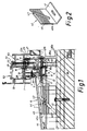
- the hollow profile 1, preferably made of plastic, has one with 3 designated indentation chamber formed on the outer surface 4 is opened by a web of the hollow profile 1, i.e. one Insertion channel for an engagement nose 5, not further specified a prop 6.
- the support 6 preferably consists of an extruded Hollow aluminum profile and has a substantially according to FIG. 1 triangular shape.
- the support 6 is used for example a weather plate 7 which, after the support 6 has been attached placed above the support 6 on this and opposite Hollow profile 1 is screwed.
- the hollow profile 1 is shown in FIG. 1 in the region of the engagement chamber 3 provided with a nose 4a which extends vertically downwards, which partially closes the engagement chamber 3 towards the top and defines a contact surface for the engagement nose 5 of the support 6, the engagement nose 5 of the support 6 essentially runs vertically (Fig. 1) and approximately perpendicular to the plane of Support 6 is at the lower area of the support 6 in FIG. 1 an essentially horizontal rib 8 is formed, after the support 6 has been attached to the hollow profile 1 in a likewise horizontally extending receiving groove 9 of the Hollow profile 1 comes to rest and thereby the positioning the support 6 relative to the hollow profile 1 causes.
- the support 6 has an end face facing the hollow profile 1 11, from which the rib 8 projects approximately vertically and from which displaces the nose 5 in the direction of the hollow profile 2 is so that the nose 5 engages behind the nose 4a as soon as the Support 6 is engaged or inserted into the hollow profile 1.
- the support 6 is on by a Web 12 defined extension of the outer surface 4 of the hollow profile 1 on, i.e. the support 6 is in its shown in Fig. 1 Condition partially flat on the hollow profile 1.
- the hollow profile 1 has a horizontal web connected to the web 4 13 in the area of the upper side of the hollow profile 1 and a horizontal web 14 in the lower region, the webs 13, 14 by a further one, in the direction of the hollow profile 2 offset web 15 are interconnected.
- the Web 15 is defined in terms of shape by a further engagement chamber 16, the engagement chamber 16 is approximately the same, but has a mirror-symmetrical design like the indentation chamber 3 and wherein the engagement chamber 16 as a nose Extension of the web 15 covered in the manner of a projection is, this nose is designated 17.
- the one labeled 15a lower web section is in alignment with the upper web section 15.
- the aluminum profile 2 is with a angled leg 18 provided by a vertical Web 20 of the hollow profile 2 protrudes to the left in Fig.
- the parallel to the web 20 and at a distance extending further web 21 defines the other side of the Hollow section 2.
- At the top of the hollow section are two behind above-reaching web sections 22, 23 are provided, of which the web section 2 in an approximately vertical and after groove 24 of the hollow profile which engages at the top while the web portion 23 at its free end with a latch 23a is provided and in a corresponding side of the hollow profile engage extending locking groove 1c in the hollow profile 1 can.
- the profile section located above the hollow profile 2 1a of the hollow profile 1 thus overlaps the hollow profile 2 and partially engages in the hollow profile 2 in the area between the two web sections 22, 23 when the two Hollow sections 1, 2 comply with the arrangement shown in Fig. 1.
- FIG. 1 Referred.
- the hollow profile 2 with a provided approximately central transverse web 28, the vertical Crosspieces 20, 21 interconnect and in addition to that upper and lower, not specified crossbar runs.
- the web portion 22 with a locking lug corresponding to the Latch 23 may be provided, and the profile section 1a has in this case, a locking groove corresponding to this locking lug, so that both the web section 22 and the web section 23 in engage corresponding locking grooves in profile section 1a.
- screwing means starting from the hollow profile 2 screw through the hollow profile 1 and opposite screwing a screw channel, screw holes or the like, provided in the support 6 and designated 30 in Fig. 1 are.
- These screw holes or screw channels 30 are in the position of the support 6 shown in Fig. 1 substantially in the horizontal direction and are in the profile of the Support 6 formed, which is preferably made of extruded aluminum consists.
- screwing means 32 provided the 1, for example, screwed into the hollow profile 2 from below and a support compared to one in FIG. 1 cause with 34 designated building.
- screw-in means 32 can be used to support the connection profile
- Angle 36 can be used, which is a substantially vertical Web 36a and a horizontal, lying on the structure 34 Has foot 36b.
- This angle 36 can on the Hollow profile 2 facing surface be grooved and in an associated Creasing on the surface of the hollow profile facing it 2 engage, using the screws labeled 38 an intimate connection in the area of the grooved surfaces between hollow profile 2 and angle 36 is ensured.
- each angle 40 is with its base surface 41st using screws and dowels on the surface of the structure 34 anchored. Furthermore, each angle 40 is inclined Provide slot 43, with the help of a positioning versus an essentially horizontal one Screw channel, a screw hole or the like possible is provided in the support 6 at different positions and is denoted by 44 in FIG. 1, for example. In Fig. 1, however, the angle 40 is opposite a screw hole or another screw channel fixed to the right of Screw channel 44 is shown in Fig. 1 and designated 44 ' is.
- this wall provided with predetermined breaking points or bending points, which are indicated at 46 and a shortening of the vertical Allow legs to a desired length.
- connection profile described above with reference to FIG. 1 is in the illustrated embodiment below profile parts 51, 52, 53, which for example to the side end or to the end opposite serve to put on window units.
- FIG. 3 shows one compared to the embodiment according to FIG. 1 modified embodiment, the same parts with the same 1 are provided and not again to be discribed.
- At the bottom of the hollow section 2 is screwed through screw 60 an angle 62, the vertically extending legs of the angle 62 on the profile 2 from below, while the vertical leg 62b of the Anchor 62 anchored on the building side by further screw means 64 is, the building is designated 66.
- the outer surfaces of the angle 62 can also in this embodiment be grooved to adjust the height compared to building 66, i.e. in the vertical direction, too enable and on the other hand also with grooves Disks 68, 69 engage, creating a reciprocal Engagement between the grooves at the bottom of the Profile 2 on the one hand and the opposite grooved surface the angle 62 is guaranteed on the other hand.
- same thing applies to the interlocking between one on the building side on the structure 66 arranged metal plate 70 which at the angle 62 facing surface is grooved, and the vertical Leg 62b of the angle 62.
- the hollow profiles facing the outside 1 made of an insulating material, preferably plastic, produce and the hollow profile 2, arranged on the room side is to manufacture from extruded aluminum.
- the intimate connection between the two hollow profiles 1 and 2 results high stability and at the same time the desired insulation between outside and room side.
- the support designated in Fig. 1 with 6 serves, as mentioned, for Edition of a weather plate 7, the screw 74 on the Hollow profile 1 can be attached.
- the weather sheet 7 easily in the remaining space between the outside profile 51 and to use the hollow section 1 is in the support 6 near the Snap lip 5 has an approximately part-circular groove 76 provided which the attachment of the angled to the connection profile Weather plate 7 facilitates and retrofitting the weather plate 7 is also possible.
- the support 6 also has the purpose that the weather plate 7th after its attachment and arrangement on the connecting profile can be walked on.
- the two hollow profiles 1 and 2 are aligned essentially with each other, as can be seen from the drawings.
- a profile chamber 78 designed to hold a holding profile 79 is used for a film 80 or the like, the room side of the profile 2 projecting vertically downwards, then for example horizontally continued is provided.
- Fig. 4 shows a modified embodiment of the invention Connection profile. Compared to Fig. 1, the same parts are in Fig. 4 provided with the same reference numerals.
- the nose 17 of the hollow profile 1 formed on the lower right side of the hollow section 1 in FIG. 4 and is engaged with a bent leg 18, on the lower left side of the hollow profile in FIG. 4 2 is formed.
- the hollow profile 1 compared to the hollow profile 2 on the lower Connection area of both hollow sections received what opposite the embodiment of, for example, Fig. 1 result has that the stability of the connection is increased and that with 16 designated in Fig. 1 ff. Omitted.
Landscapes
- Engineering & Computer Science (AREA)
- Civil Engineering (AREA)
- Structural Engineering (AREA)
- Mechanical Engineering (AREA)
- Joining Of Building Structures In Genera (AREA)
Applications Claiming Priority (2)
| Application Number | Priority Date | Filing Date | Title |
|---|---|---|---|
| DE19921858 | 1999-05-11 | ||
| DE1999121858 DE19921858A1 (de) | 1999-05-11 | 1999-05-11 | Anschlußprofil für Fassaden, Fenster oder dergleichen |
Publications (1)
| Publication Number | Publication Date |
|---|---|
| EP1052361A1 true EP1052361A1 (fr) | 2000-11-15 |
Family
ID=7907804
Family Applications (1)
| Application Number | Title | Priority Date | Filing Date |
|---|---|---|---|
| EP00109084A Withdrawn EP1052361A1 (fr) | 1999-05-11 | 2000-05-03 | Profilé de jonction pour façades, fenêtres et similaires |
Country Status (2)
| Country | Link |
|---|---|
| EP (1) | EP1052361A1 (fr) |
| DE (1) | DE19921858A1 (fr) |
Cited By (2)
| Publication number | Priority date | Publication date | Assignee | Title |
|---|---|---|---|---|
| EP1832705A1 (fr) | 2006-03-07 | 2007-09-12 | Susanne Haager | Structure d'appui ou d'étanchéification d'une ouverture de bâtiment d'un élément obturateur, par exemple, une fenêtre, une porte ou analogue |
| WO2007110849A1 (fr) * | 2006-03-28 | 2007-10-04 | Kingspan Holdings (Irl) Limited | Système d'isolation de rebord |
Families Citing this family (1)
| Publication number | Priority date | Publication date | Assignee | Title |
|---|---|---|---|---|
| DE102006020228A1 (de) * | 2006-04-27 | 2007-10-31 | Sylid Systemlogistik Und Industriedienstleistung Gmbh | Montagesystem für Fenster und dergleichen |
Citations (2)
| Publication number | Priority date | Publication date | Assignee | Title |
|---|---|---|---|---|
| DE3221753A1 (de) * | 1982-06-09 | 1983-12-15 | Herbert 6782 Rodalben Borkhoff | Aeusseres mauerabdeck - und montagesystem fuer fenster, tueren und fassaden |
| EP0787880A1 (fr) * | 1996-01-31 | 1997-08-06 | Peter Willrich | Dispositif de réglage de hauteur pour une finition en partie inférieure de portes ou de fenêtres |
Family Cites Families (3)
| Publication number | Priority date | Publication date | Assignee | Title |
|---|---|---|---|---|
| DE9318973U1 (de) * | 1993-12-10 | 1994-02-10 | Siegenia-Frank Kg, 57074 Siegen | Bodenschwelle bzw. Abdeckprofil für Blendrahmen von Schiebe- oder Hebe-Schiebefenstern und -türen o.dgl. |
| DE29701604U1 (de) * | 1997-01-28 | 1997-03-27 | HT Troplast AG, 53840 Troisdorf | Profilsystem zur Herstellung von Türen |
| DE29809233U1 (de) * | 1998-05-26 | 1998-11-26 | Holthus, Klaus-Dieter, 31619 Binnen | Alu-Fensterbank mit einem Montageclip |
-
1999
- 1999-05-11 DE DE1999121858 patent/DE19921858A1/de not_active Ceased
-
2000
- 2000-05-03 EP EP00109084A patent/EP1052361A1/fr not_active Withdrawn
Patent Citations (2)
| Publication number | Priority date | Publication date | Assignee | Title |
|---|---|---|---|---|
| DE3221753A1 (de) * | 1982-06-09 | 1983-12-15 | Herbert 6782 Rodalben Borkhoff | Aeusseres mauerabdeck - und montagesystem fuer fenster, tueren und fassaden |
| EP0787880A1 (fr) * | 1996-01-31 | 1997-08-06 | Peter Willrich | Dispositif de réglage de hauteur pour une finition en partie inférieure de portes ou de fenêtres |
Cited By (3)
| Publication number | Priority date | Publication date | Assignee | Title |
|---|---|---|---|---|
| EP1832705A1 (fr) | 2006-03-07 | 2007-09-12 | Susanne Haager | Structure d'appui ou d'étanchéification d'une ouverture de bâtiment d'un élément obturateur, par exemple, une fenêtre, une porte ou analogue |
| WO2007110849A1 (fr) * | 2006-03-28 | 2007-10-04 | Kingspan Holdings (Irl) Limited | Système d'isolation de rebord |
| GB2436714B (en) * | 2006-03-28 | 2010-12-22 | Kingspan Holdings | A cill insulating system |
Also Published As
| Publication number | Publication date |
|---|---|
| DE19921858A1 (de) | 2000-11-30 |
Similar Documents
| Publication | Publication Date | Title |
|---|---|---|
| DE4447144C2 (de) | Trägersystem für elektrische Leitungen | |
| DE10136681C2 (de) | Rahmengestell | |
| DE3726255C2 (de) | Trennwand | |
| EP0436869A2 (fr) | Liaison au niveau du raccordement entre poteau et traverse d'une structure porteuse pour ou un mur de façade | |
| EP0104428B1 (fr) | Latte ou plaque de support d'un revêtement de rideau pour un mur ou plafond | |
| DE2610998C3 (de) | Halterung zur Befestigung von Bekleidungsplatten vor einer Bauwerkswand | |
| EP2589725B1 (fr) | Élément de liaison et système de profil d'aération pour façades de bâtiments ventilées à l'arrière | |
| EP1870529A1 (fr) | Mur/ensemble de coffre pour une construction de cadre | |
| EP0364768B1 (fr) | Elément de cloison de séparation | |
| EP3889384A1 (fr) | Profilé extrudé de section creuse de fenêtre ou de porte, système doté d'un tel profilé de section creuse et cadre fabriqué à partir de celui-ci | |
| EP3091133B1 (fr) | Système de retenue pour éléments de paroi | |
| DE9203467U1 (de) | Bauelementsatz und daraus hergestellte Zellenanordnung | |
| EP1052360A1 (fr) | Profilé de jonction pour façades, fenêtres et similaires | |
| DE29508686U1 (de) | Bausatz zum Erstellen von Umkleidekabinen, Trennwänden u.dgl. | |
| DE29509555U1 (de) | Schaltschrank mit Montageplatte als Einzel- oder Anreihschrank | |
| DE19921858A1 (de) | Anschlußprofil für Fassaden, Fenster oder dergleichen | |
| DE4421614C2 (de) | Fassadenverkleidung | |
| EP0348853A2 (fr) | Tendeur | |
| CH624449A5 (en) | Device for connecting a covering frame to a base frame for windows, facades or room partitions | |
| EP0213451B1 (fr) | Rail pour une construction de support d'un bardage de mur ou plafond | |
| CH707596A2 (de) | Halteprofil. | |
| CH683438A5 (de) | Profilierte Abstand- und Halteleiste. | |
| DE3833964A1 (de) | Befestigungssystem fuer unterdecken | |
| DE19860743C1 (de) | Wandhalter für Verkleidungstafeln, insbesondere Fassadenelemente | |
| EP1388627B1 (fr) | Dispositif de fixation pour une ferrure |
Legal Events
| Date | Code | Title | Description |
|---|---|---|---|
| PUAI | Public reference made under article 153(3) epc to a published international application that has entered the european phase |
Free format text: ORIGINAL CODE: 0009012 |
|
| AK | Designated contracting states |
Kind code of ref document: A1 Designated state(s): AT CH DE LI LU |
|
| AX | Request for extension of the european patent |
Free format text: AL;LT;LV;MK;RO;SI |
|
| 17P | Request for examination filed |
Effective date: 20010412 |
|
| AKX | Designation fees paid |
Free format text: AT CH DE LI LU |
|
| STAA | Information on the status of an ep patent application or granted ep patent |
Free format text: STATUS: THE APPLICATION IS DEEMED TO BE WITHDRAWN |
|
| 18D | Application deemed to be withdrawn |
Effective date: 20021202 |