EP1052363A1 - Cadre de profilés, notamment de profilés en U pour le maintien d'éléments planes commes des vitres, des panneaux en matière plastique et similaires - Google Patents
Cadre de profilés, notamment de profilés en U pour le maintien d'éléments planes commes des vitres, des panneaux en matière plastique et similaires Download PDFInfo
- Publication number
- EP1052363A1 EP1052363A1 EP99109138A EP99109138A EP1052363A1 EP 1052363 A1 EP1052363 A1 EP 1052363A1 EP 99109138 A EP99109138 A EP 99109138A EP 99109138 A EP99109138 A EP 99109138A EP 1052363 A1 EP1052363 A1 EP 1052363A1
- Authority
- EP
- European Patent Office
- Prior art keywords
- leg
- profile frame
- tooth
- stop
- groove
- Prior art date
- Legal status (The legal status is an assumption and is not a legal conclusion. Google has not performed a legal analysis and makes no representation as to the accuracy of the status listed.)
- Withdrawn
Links
- 239000004033 plastic Substances 0.000 title claims abstract description 11
- 229920003023 plastic Polymers 0.000 title claims abstract description 11
- 239000011521 glass Substances 0.000 claims abstract description 9
- 230000015572 biosynthetic process Effects 0.000 claims description 37
- 230000008719 thickening Effects 0.000 claims description 14
- PWHULOQIROXLJO-UHFFFAOYSA-N Manganese Chemical compound [Mn] PWHULOQIROXLJO-UHFFFAOYSA-N 0.000 claims description 4
- XUIMIQQOPSSXEZ-UHFFFAOYSA-N Silicon Chemical compound [Si] XUIMIQQOPSSXEZ-UHFFFAOYSA-N 0.000 claims description 4
- 229910052748 manganese Inorganic materials 0.000 claims description 4
- 239000011572 manganese Substances 0.000 claims description 4
- 229910052710 silicon Inorganic materials 0.000 claims description 4
- 239000010703 silicon Substances 0.000 claims description 4
- 229910000838 Al alloy Inorganic materials 0.000 claims description 3
- 210000002414 leg Anatomy 0.000 description 103
- 238000007373 indentation Methods 0.000 description 10
- 239000000853 adhesive Substances 0.000 description 4
- 230000001070 adhesive effect Effects 0.000 description 4
- 210000000078 claw Anatomy 0.000 description 3
- 238000009434 installation Methods 0.000 description 3
- 238000004519 manufacturing process Methods 0.000 description 3
- 238000000034 method Methods 0.000 description 3
- 239000000654 additive Substances 0.000 description 2
- 229910052782 aluminium Inorganic materials 0.000 description 2
- XAGFODPZIPBFFR-UHFFFAOYSA-N aluminium Chemical compound [Al] XAGFODPZIPBFFR-UHFFFAOYSA-N 0.000 description 2
- 239000000463 material Substances 0.000 description 2
- 229910052751 metal Inorganic materials 0.000 description 2
- 239000002184 metal Substances 0.000 description 2
- 238000000926 separation method Methods 0.000 description 2
- 230000006978 adaptation Effects 0.000 description 1
- 230000000996 additive effect Effects 0.000 description 1
- 238000005516 engineering process Methods 0.000 description 1
- 239000003000 extruded plastic Substances 0.000 description 1
- 238000001125 extrusion Methods 0.000 description 1
- 210000003746 feather Anatomy 0.000 description 1
- 238000003780 insertion Methods 0.000 description 1
- 230000037431 insertion Effects 0.000 description 1
- 238000012986 modification Methods 0.000 description 1
- 230000004048 modification Effects 0.000 description 1
- 238000000465 moulding Methods 0.000 description 1
- 238000003825 pressing Methods 0.000 description 1
- 230000000284 resting effect Effects 0.000 description 1
- 230000000630 rising effect Effects 0.000 description 1
- 238000007789 sealing Methods 0.000 description 1
- 238000003860 storage Methods 0.000 description 1
- 210000000689 upper leg Anatomy 0.000 description 1
Images


Classifications
-
- E—FIXED CONSTRUCTIONS
- E05—LOCKS; KEYS; WINDOW OR DOOR FITTINGS; SAFES
- E05D—HINGES OR SUSPENSION DEVICES FOR DOORS, WINDOWS OR WINGS
- E05D15/00—Suspension arrangements for wings
- E05D15/06—Suspension arrangements for wings for wings sliding horizontally more or less in their own plane
- E05D15/0621—Details, e.g. suspension or supporting guides
- E05D15/0626—Details, e.g. suspension or supporting guides for wings suspended at the top
-
- E—FIXED CONSTRUCTIONS
- E06—DOORS, WINDOWS, SHUTTERS, OR ROLLER BLINDS IN GENERAL; LADDERS
- E06B—FIXED OR MOVABLE CLOSURES FOR OPENINGS IN BUILDINGS, VEHICLES, FENCES OR LIKE ENCLOSURES IN GENERAL, e.g. DOORS, WINDOWS, BLINDS, GATES
- E06B3/00—Window sashes, door leaves, or like elements for closing wall or like openings; Layout of fixed or moving closures, e.g. windows in wall or like openings; Features of rigidly-mounted outer frames relating to the mounting of wing frames
- E06B3/54—Fixing of glass panes or like plates
- E06B3/58—Fixing of glass panes or like plates by means of borders, cleats, or the like
- E06B3/585—Fixing of glass panes or like plates by means of borders, cleats, or the like adjustable, e.g. for accommodating panes of various thickness, or with provisions for altering the clamping force on the pane
- E06B3/5857—Fixing of glass panes or like plates by means of borders, cleats, or the like adjustable, e.g. for accommodating panes of various thickness, or with provisions for altering the clamping force on the pane the fixing being adjustable, e.g. in one of several possible positions
-
- E—FIXED CONSTRUCTIONS
- E05—LOCKS; KEYS; WINDOW OR DOOR FITTINGS; SAFES
- E05Y—INDEXING SCHEME ASSOCIATED WITH SUBCLASSES E05D AND E05F, RELATING TO CONSTRUCTION ELEMENTS, ELECTRIC CONTROL, POWER SUPPLY, POWER SIGNAL OR TRANSMISSION, USER INTERFACES, MOUNTING OR COUPLING, DETAILS, ACCESSORIES, AUXILIARY OPERATIONS NOT OTHERWISE PROVIDED FOR, APPLICATION THEREOF
- E05Y2600/00—Mounting or coupling arrangements for elements provided for in this subclass
- E05Y2600/10—Adjustable
- E05Y2600/30—Adjustment motion
- E05Y2600/33—Stepwise motion
-
- E—FIXED CONSTRUCTIONS
- E05—LOCKS; KEYS; WINDOW OR DOOR FITTINGS; SAFES
- E05Y—INDEXING SCHEME ASSOCIATED WITH SUBCLASSES E05D AND E05F, RELATING TO CONSTRUCTION ELEMENTS, ELECTRIC CONTROL, POWER SUPPLY, POWER SIGNAL OR TRANSMISSION, USER INTERFACES, MOUNTING OR COUPLING, DETAILS, ACCESSORIES, AUXILIARY OPERATIONS NOT OTHERWISE PROVIDED FOR, APPLICATION THEREOF
- E05Y2600/00—Mounting or coupling arrangements for elements provided for in this subclass
- E05Y2600/50—Mounting methods; Positioning
- E05Y2600/52—Toolless
- E05Y2600/526—Gluing or cementing
-
- E—FIXED CONSTRUCTIONS
- E05—LOCKS; KEYS; WINDOW OR DOOR FITTINGS; SAFES
- E05Y—INDEXING SCHEME ASSOCIATED WITH SUBCLASSES E05D AND E05F, RELATING TO CONSTRUCTION ELEMENTS, ELECTRIC CONTROL, POWER SUPPLY, POWER SIGNAL OR TRANSMISSION, USER INTERFACES, MOUNTING OR COUPLING, DETAILS, ACCESSORIES, AUXILIARY OPERATIONS NOT OTHERWISE PROVIDED FOR, APPLICATION THEREOF
- E05Y2600/00—Mounting or coupling arrangements for elements provided for in this subclass
- E05Y2600/60—Mounting or coupling members; Accessories therefor
- E05Y2600/628—Profiles; Strips
-
- E—FIXED CONSTRUCTIONS
- E05—LOCKS; KEYS; WINDOW OR DOOR FITTINGS; SAFES
- E05Y—INDEXING SCHEME ASSOCIATED WITH SUBCLASSES E05D AND E05F, RELATING TO CONSTRUCTION ELEMENTS, ELECTRIC CONTROL, POWER SUPPLY, POWER SIGNAL OR TRANSMISSION, USER INTERFACES, MOUNTING OR COUPLING, DETAILS, ACCESSORIES, AUXILIARY OPERATIONS NOT OTHERWISE PROVIDED FOR, APPLICATION THEREOF
- E05Y2800/00—Details, accessories and auxiliary operations not otherwise provided for
- E05Y2800/15—Applicability
- E05Y2800/17—Universally applicable
-
- E—FIXED CONSTRUCTIONS
- E05—LOCKS; KEYS; WINDOW OR DOOR FITTINGS; SAFES
- E05Y—INDEXING SCHEME ASSOCIATED WITH SUBCLASSES E05D AND E05F, RELATING TO CONSTRUCTION ELEMENTS, ELECTRIC CONTROL, POWER SUPPLY, POWER SIGNAL OR TRANSMISSION, USER INTERFACES, MOUNTING OR COUPLING, DETAILS, ACCESSORIES, AUXILIARY OPERATIONS NOT OTHERWISE PROVIDED FOR, APPLICATION THEREOF
- E05Y2800/00—Details, accessories and auxiliary operations not otherwise provided for
- E05Y2800/15—Applicability
- E05Y2800/17—Universally applicable
- E05Y2800/178—Universally applicable on wings having different thicknesses
-
- E—FIXED CONSTRUCTIONS
- E05—LOCKS; KEYS; WINDOW OR DOOR FITTINGS; SAFES
- E05Y—INDEXING SCHEME ASSOCIATED WITH SUBCLASSES E05D AND E05F, RELATING TO CONSTRUCTION ELEMENTS, ELECTRIC CONTROL, POWER SUPPLY, POWER SIGNAL OR TRANSMISSION, USER INTERFACES, MOUNTING OR COUPLING, DETAILS, ACCESSORIES, AUXILIARY OPERATIONS NOT OTHERWISE PROVIDED FOR, APPLICATION THEREOF
- E05Y2800/00—Details, accessories and auxiliary operations not otherwise provided for
- E05Y2800/20—Combinations of elements
- E05Y2800/205—Combinations of elements forming a unit
Definitions
- the invention relates to a profile frame, in particular.
- U-profile frame for holding surface elements such as Glass panes, plastic plates or the like, with an as Stop leg designed U-leg for fixing one side of the surface element, with an as Fixing leg executed other U-legs for Definition of the other side of the surface element, and with a U-base designed as a support leg, the Support leg essentially perpendicular to the Stop leg to form an L-shaped receiving leg is connected for the surface element, where also the fixing leg in the course of the attachment of the Panel element clamped between the stop legs and locking leg lockable with the receiving leg is, wherein the fixing leg by means of a Tongue and groove connection connectable to the receiving leg is, and wherein the fixing leg, the spring and the Receiving leg has the groove, or vice versa.
- a profile frame of the configuration described above is known from the German utility model 297 18 854 become.
- a generic embodiment is in the WO 95/22 676.
- the procedure is such that the Fixing leg is pivotable and in the course of Fastening of the surface element via locking latches on L-shaped receiving leg is held.
- the procedure is unsatisfactory from an assembly point of view, especially since the swivel mounting by one in one Semicircular engaging pin is realized.
- the known embodiment in terms the thickness of the surface element to be clamped to one extremely small thickness range is restricted. This has as a result that for different strength glass or Plastic panes or plates each have adapted profile frames need to be stocked.
- Profile frame of the configuration described above are generally used in conjunction with sliding element devices used, such as by the European Patent 0 577 669 have become known. In this context, they mainly serve one movable sliding element or a surface element on its To fix the top and bottom edge. - Of course are also all other applications of the described Profile frame for holding surface elements in the frame the invention. Without a doubt, this also includes Fixed installation of glass panes in building openings, from Plastic plate brackets on building walls, etc. - In any case, the state of the art may not work in all Satisfy points.
- the invention is based on the technical problem, one Profile frame of the configuration described above to train that flexible adaptation to different Strengths of the surface element is made possible and at the same time a perfect mounting and mounting and dismantling succeed.
- the invention proposes generic profile frame, in particular U-profile frame for holding surface elements such as glass panes, Plastic plates or the like.
- the spring or Spring leg has a toothing that in a appropriate tooth formation in the groove or the groove channel intervenes.
- the Teeth formed on the top of the spring leg and has at least one triangular tooth, which in engages at least one triangular tooth formation.
- This has guide and clamp thickening generally one to one in the groove leg in Locking direction arranged behind the tooth formation Guide and clamp receptacle adapted thickness.
- Words is the strength or thickness of the leadership and Clamping thickening to the clear width behind the Tooth formation provided guide and clamping receptacle customized. This is with reference to the figure description to be explained in more detail. In any case, this is one flawless introduction, guidance and mounting of the Feather leg reached.
- the triangular tooth can be in cross section as an equilateral or be formed isosceles triangle, the base of which with the top of the guide and clamp thickening coincides.
- the Tooth formation at least one corresponding triangular tooth formation in the form of a tooth formation isosceles or isosceles cross section.
- the basis of this tooth formation falls with the Extension of the top of the guide and clamp receptacle together.
- the triangular tooth is preferably in the Cross section as a right triangle with on the Guide and clamp thickening vertical on the upper side rising barb flank and adjoining it Stop tooth flank formed.
- Triangular tooth formation is therefore in cross section as a catheter open right triangle with vertical arranged for transverse extension of the spring leg Barb tooth formation and the hypotenuse (of the triangle) Representative stop tooth formation executed.
- barb tooth flank and barb tooth formation formed a barb, which is a separation of the fixation leg and on the other hand, receiving leg prevented.
- a precise fit of different strengths Surface elements possible if the teeth at least has a tooth which in an associated Tooth molding with several molded and in Locking direction teeth arranged one behind the other intervenes.
- Profile frame as an extruded profile made of an aluminum alloy made with manganese and silicon additives. Because such a design is not only easy and durable, but can also be easily design in color or with a plastic cover Mistake. Accordingly, a surface design achievable that the previously outlined different Installation conditions (fixed installation or consideration in Connection with sliding element devices) takes into account.
- the aforementioned choice of materials is large Allows elasticity so that the spring leg through Lifting the support leg (after removing the resting surface element) from the groove or the groove channel can be pulled while separating the profile frame. Consequently, disassembly of the surface element is in at the same time perfect and precise mounting possible.
- the inclusion of surface elements is also successful different thicknesses with a single profile frame, so that the manufacturing and storage costs compared to the stand the technology (WO 95/22 676) are significantly reduced.
- a profile frame according to the Embodiment an extruded profile frame, shown which is made of an aluminum alloy with manganese and Silicon additive is made.
- This profile frame is a U-profile frame for holding Surface elements 1, according to the embodiment Panes of glass.
- This U-profile frame has a basic structure U-legs 2a designed as stop legs 2a for Fixing a side 1a of the surface element 1.
- a fixing leg 3a other U-leg 3a to fix the other side 1b of the surface element 1.
- a Support legs 2b designed U-base 2b provided. It it should be emphasized that according to the embodiment two U-legs 2a, 3a substantially perpendicular to U-base 2b are arranged, but also any other angles are encompassed by the invention.
- the support leg 2b is essentially vertical the stop leg 2a to form an L-shaped Receiving leg 2 connected to the surface element 1, molded in the embodiment.
- the fixing leg 3a is in the course of fastening the surface element 1 under Clamping between stop leg 2a and fixing leg 3a lockable with the receiving leg 2, like this 2 and 3 can be seen in particular.
- Locking is the fixing leg 3a by means of a Tongue and groove connection 3b, 5 with the receiving leg 2 connectable.
- This tongue and groove connection 3b, 5 acts it is a spring or a spring leg 3b, which engages in a groove or a groove channel 5.
- fixing leg 3a with the receiving leg 2 so connected that the fixing leg 3a with its spring 3b or the spring leg 3b into the groove or the groove channel 5 of the receiving leg 2 engages.
- fixing leg 3a also basically the groove or have the groove channel 5, while the tongue or Spring leg 3b is arranged on the receiving leg 2.
- a groove leg 4 is provided, which together with the one above Support leg 2a the aforementioned rectangular Groove channel 5 or the groove 5 forms.
- the fixing leg 3a has the associated spring leg 3b or the spring 3b on the fixing leg 3a is molded.
- the spring leg 3b is after Embodiment perpendicular to the fixing leg 3a arranged and forms an L-shaped with this Pressure leg 3.
- the fixing leg 3a or Pressure leg 3 is in the groove channel 5 in Locking direction V insertable spring leg 3b lockable with the receiving leg 2.
- the profile frame according to the invention essentially from two L-shaped legs 2, 3.
- that of the two respective L-legs 2a and 2b or 3a and 3b included angles are not mandatory right angle must be, but basically other Angle arrangements are conceivable.
- Both of the aforementioned legs 2, 3 can be simple, inexpensive and fast in one go Manufacture aluminum extrusion process. Of course can also extruded plastic profiles at this point are used.
- the grooved leg 4 is parallel to the support leg 2b arranged (see. Fig. 1, 2).
- the Support leg 2b to the thickness B of the to be clamped surface element 1 adapted length L. (see in particular FIGS. 2 and 3).
- the groove leg 4 has according to the embodiment, a leading edge 6 of the Support leg 2b protruding by a predetermined amount M. Length. That is, the length of the nut leg 4 continues in essentially from the sum of L + M.
- the spring leg 3b has a toothing 7, which in a corresponding tooth formation 8 engages in the groove channel 5.
- the aforementioned toothing 7 is on the top of the spring leg 3b arranged in the embodiment molded on the top. 2 to 4 clearly that the toothing 7 shown at least one Triangular tooth 9 has.
- This triangular tooth 9 engages at least one corresponding triangular tooth indentation 10 on. 2 to 4 are three each Triangular tooth indentations 10 shown, in which a only triangular tooth 9 engages.
- Embodiment according to FIGS. 2 and 3 is the triangular tooth 9 there in cross section as right triangle with on the guide and Clamping thickening 11 vertical barb tooth flank 9a and the subsequent stop tooth flank 9b executed.
- Barb tooth flank 9a and stop tooth flank 9b Angle ⁇ of approx. 70 °.
- ⁇ can also Accept values between 60 ° and 80 °.
- the corresponding triangular tooth formation 10 is in the Cross-section as a right-angled open on a cathete Triangle executed. There is one perpendicular to Transverse extension of the spring leg 3b arranged barb tooth formation 10a, to which one Stop tooth formation 10b connects, as it were the Hypotenuse of the open right triangle. Barb Tooth 10a and Stop Tooth 10b close the angle according to the embodiment ⁇ between them, which is approximately 70 °. Of course At this point there are values of ⁇ between 60 ° and 80 ° possible.
- the depth T of the tooth formation 8 and the corresponding one Height H of the toothing 7 engaging here are thus dimensioned that the support leg 2b elastically upwards bent and thus toothing 7 and tooth formation 8 except Intervention can be brought (cf. the double arrow in Fig. 2). Accordingly, receiving legs 2 and Press leg 3 flawlessly and without damage to Separate the profile frame. This is supported by choice of material to produce the shown Profile frame (aluminum with manganese and silicon addition).
- the stop leg 2a and Fixing leg 3a inside, the adjacent Pages 1a, 1b of the surface element 1 facing Indentations 15, which are present as rounded rectangular indentations 15 for receiving not shown Serve adhesive adhesive.
- the indentations 15 are it is longitudinal grooves.
- For the rest is in underside extension of the fixing leg 3a Locking leg 18 with locking lug 19 for fixing the Lock leg 18 provided.
- the locking lug 19 cooperates a locking projection 20 together, which on one Fastening claw leg 16a is formed.
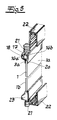
- the profile frame is a rail 17, which between the two Fastening claw legs 16a, 16b is held.
- rollers 21 are connected, which for guidance of the surface element 1 as a sliding element in an upper and serve lower profile bar 22.
- lateral Cover caps 23 may be provided.
Landscapes
- Engineering & Computer Science (AREA)
- Civil Engineering (AREA)
- Structural Engineering (AREA)
- Mechanical Engineering (AREA)
- Mutual Connection Of Rods And Tubes (AREA)
Priority Applications (1)
| Application Number | Priority Date | Filing Date | Title |
|---|---|---|---|
| EP99109138A EP1052363A1 (fr) | 1999-05-08 | 1999-05-08 | Cadre de profilés, notamment de profilés en U pour le maintien d'éléments planes commes des vitres, des panneaux en matière plastique et similaires |
Applications Claiming Priority (1)
| Application Number | Priority Date | Filing Date | Title |
|---|---|---|---|
| EP99109138A EP1052363A1 (fr) | 1999-05-08 | 1999-05-08 | Cadre de profilés, notamment de profilés en U pour le maintien d'éléments planes commes des vitres, des panneaux en matière plastique et similaires |
Publications (1)
| Publication Number | Publication Date |
|---|---|
| EP1052363A1 true EP1052363A1 (fr) | 2000-11-15 |
Family
ID=8238139
Family Applications (1)
| Application Number | Title | Priority Date | Filing Date |
|---|---|---|---|
| EP99109138A Withdrawn EP1052363A1 (fr) | 1999-05-08 | 1999-05-08 | Cadre de profilés, notamment de profilés en U pour le maintien d'éléments planes commes des vitres, des panneaux en matière plastique et similaires |
Country Status (1)
| Country | Link |
|---|---|
| EP (1) | EP1052363A1 (fr) |
Cited By (11)
| Publication number | Priority date | Publication date | Assignee | Title |
|---|---|---|---|---|
| RU2272884C2 (ru) * | 2004-05-24 | 2006-03-27 | Олег Николаевич Куликов | Уплотнительное устройство для крепления стекла |
| DE102008004751B3 (de) * | 2008-01-16 | 2009-08-06 | Geze Gmbh | Klemmbeschlag |
| WO2010003260A1 (fr) | 2008-07-07 | 2010-01-14 | Eku Ag | Dispositif de support pour une porte coulissante |
| DE102008046850A1 (de) * | 2008-09-08 | 2010-03-18 | Joma-Polytec Kunststofftechnik Gmbh | Träger für Photovoltaikmodule sowie zugehörige Baugruppe und zugehöriges Montageverfahren |
| DE202010012157U1 (de) | 2010-09-02 | 2010-11-25 | Tittel, Karsten | Türblattbefestigung |
| CN102094566A (zh) * | 2011-01-13 | 2011-06-15 | 杨建标 | 自固玻璃锁扣及其应用方法 |
| EP2865838A1 (fr) * | 2013-10-24 | 2015-04-29 | Dutch Global Sourcing B.V. | Cadre de fenêtre |
| EP3034735B1 (fr) | 2014-12-15 | 2017-10-25 | dormakaba Deutschland GmbH | Système de paroi coulissante ayant au moins un élément de battant de porte doté d'une vitre et procédé de fixation de cette vitre dans le système de paroi coulissante |
| CN111911042A (zh) * | 2020-08-31 | 2020-11-10 | 湖南省金为新材料科技有限公司 | 侧装式极窄门窗系统 |
| CN112273945A (zh) * | 2020-11-06 | 2021-01-29 | 南京至美畅和科技会展股份有限公司 | 一种可调式展示型材 |
| RU212943U1 (ru) * | 2022-01-27 | 2022-08-15 | Общество с ограниченной ответственностью "СКС-Штакузит" | Зажим для стекла |
Citations (7)
| Publication number | Priority date | Publication date | Assignee | Title |
|---|---|---|---|---|
| US3918231A (en) * | 1972-02-15 | 1975-11-11 | Gerald Kessler | Frost resistant window sash |
| DE2614803A1 (de) * | 1976-04-06 | 1977-10-27 | Syco Prod Entwicklungs Gmbh | Glasfalzleiste |
| FR2542762A1 (fr) * | 1983-03-18 | 1984-09-21 | Italia Alluminio | Alliage d'aluminium pour elements de fermeture blindes antiprojectiles |
| EP0182227A2 (fr) * | 1984-11-13 | 1986-05-28 | Haas, Otto | Parclose |
| EP0577669A1 (fr) | 1991-03-27 | 1994-01-12 | Jarmo Sjoeholm | Systeme a element coulissant. |
| WO1995022676A1 (fr) | 1994-02-21 | 1995-08-24 | Sjoeholm Jarmo | Profiles de vitrage |
| DE29718854U1 (de) | 1997-10-23 | 1998-01-02 | Sks Stakusit Kunststoff Gmbh | Profilrahmen, insbesondere U-Profilrahmen zur Halterung von Flächenelementen wie Glasscheiben, Kunststoffplatten o.dgl. |
-
1999
- 1999-05-08 EP EP99109138A patent/EP1052363A1/fr not_active Withdrawn
Patent Citations (7)
| Publication number | Priority date | Publication date | Assignee | Title |
|---|---|---|---|---|
| US3918231A (en) * | 1972-02-15 | 1975-11-11 | Gerald Kessler | Frost resistant window sash |
| DE2614803A1 (de) * | 1976-04-06 | 1977-10-27 | Syco Prod Entwicklungs Gmbh | Glasfalzleiste |
| FR2542762A1 (fr) * | 1983-03-18 | 1984-09-21 | Italia Alluminio | Alliage d'aluminium pour elements de fermeture blindes antiprojectiles |
| EP0182227A2 (fr) * | 1984-11-13 | 1986-05-28 | Haas, Otto | Parclose |
| EP0577669A1 (fr) | 1991-03-27 | 1994-01-12 | Jarmo Sjoeholm | Systeme a element coulissant. |
| WO1995022676A1 (fr) | 1994-02-21 | 1995-08-24 | Sjoeholm Jarmo | Profiles de vitrage |
| DE29718854U1 (de) | 1997-10-23 | 1998-01-02 | Sks Stakusit Kunststoff Gmbh | Profilrahmen, insbesondere U-Profilrahmen zur Halterung von Flächenelementen wie Glasscheiben, Kunststoffplatten o.dgl. |
Cited By (14)
| Publication number | Priority date | Publication date | Assignee | Title |
|---|---|---|---|---|
| RU2272884C2 (ru) * | 2004-05-24 | 2006-03-27 | Олег Николаевич Куликов | Уплотнительное устройство для крепления стекла |
| DE102008004751B3 (de) * | 2008-01-16 | 2009-08-06 | Geze Gmbh | Klemmbeschlag |
| EP2080862A3 (fr) * | 2008-01-16 | 2013-12-25 | GEZE GmbH | Ferrure de serrage |
| WO2010003260A1 (fr) | 2008-07-07 | 2010-01-14 | Eku Ag | Dispositif de support pour une porte coulissante |
| DE102008046850B4 (de) * | 2008-09-08 | 2013-04-18 | Joma-Polytec Gmbh | Träger für Photovoltaikmodule sowie zugehörige Baugruppe und zugehöriges Montageverfahren |
| DE102008046850A1 (de) * | 2008-09-08 | 2010-03-18 | Joma-Polytec Kunststofftechnik Gmbh | Träger für Photovoltaikmodule sowie zugehörige Baugruppe und zugehöriges Montageverfahren |
| DE202010012157U1 (de) | 2010-09-02 | 2010-11-25 | Tittel, Karsten | Türblattbefestigung |
| CN102094566B (zh) * | 2011-01-13 | 2012-10-24 | 杨建标 | 自固玻璃锁扣及其应用方法 |
| CN102094566A (zh) * | 2011-01-13 | 2011-06-15 | 杨建标 | 自固玻璃锁扣及其应用方法 |
| EP2865838A1 (fr) * | 2013-10-24 | 2015-04-29 | Dutch Global Sourcing B.V. | Cadre de fenêtre |
| EP3034735B1 (fr) | 2014-12-15 | 2017-10-25 | dormakaba Deutschland GmbH | Système de paroi coulissante ayant au moins un élément de battant de porte doté d'une vitre et procédé de fixation de cette vitre dans le système de paroi coulissante |
| CN111911042A (zh) * | 2020-08-31 | 2020-11-10 | 湖南省金为新材料科技有限公司 | 侧装式极窄门窗系统 |
| CN112273945A (zh) * | 2020-11-06 | 2021-01-29 | 南京至美畅和科技会展股份有限公司 | 一种可调式展示型材 |
| RU212943U1 (ru) * | 2022-01-27 | 2022-08-15 | Общество с ограниченной ответственностью "СКС-Штакузит" | Зажим для стекла |
Similar Documents
| Publication | Publication Date | Title |
|---|---|---|
| DE3218267C2 (de) | Glasscheibenhalter für einen Fensterversteller | |
| DE69705662T2 (de) | Rollvorrichtung für Schiebetüren, Fenster oder ähnliches | |
| DE2800698A1 (de) | Fliegengitter | |
| DE9207859U1 (de) | Glasscheibenhalter | |
| EP1557516B1 (fr) | Chariot pour une porte coulissante ou pliante | |
| EP0030290A2 (fr) | Tiroir | |
| DE3210468A1 (de) | Tuer- und fensterrahmen | |
| EP3112577B1 (fr) | Joint abaissable | |
| EP0182227A2 (fr) | Parclose | |
| DE202017007566U1 (de) | Möbel mit einem an einem Laufprofil verfahrbaren Schiebeelement und einer Führungseinrichtung | |
| DE1908567A1 (de) | Kombinierte Form- und Verglasungsleiste als Profilstab insbesondere zum Halten einer Glasscheibe vorzugsweise an einem Rahmen | |
| EP1718835A1 (fr) | Dispositif de fixation pour un rail de glissement ou de guidage | |
| DE29718854U1 (de) | Profilrahmen, insbesondere U-Profilrahmen zur Halterung von Flächenelementen wie Glasscheiben, Kunststoffplatten o.dgl. | |
| DE171548C (fr) | ||
| DE9317236U1 (de) | Vorrichtung zur Verriegelung eines Trennwandelementes | |
| DE2628750C3 (de) | In einer Tafelöffnung anzuordnendes MeBinstrumentengehäuse mit federnden Befestigungsklemmen | |
| DE69205091T2 (de) | Aushebevorbeugungsvorrichtung für Schiebeflügel, insbesondere einer Tür, eines Fensters oder ähnlichem. | |
| DE2524205A1 (de) | Vorrichtung zur begrenzung der aufrollbewegung eines rolladens | |
| DE2634597A1 (de) | Verbundprofil | |
| DE202009002713U1 (de) | Gleitbeschlag | |
| DE2834268A1 (de) | Lamellenjalousie | |
| DE3037703C2 (de) | Lemellenjalousie mit einem raffbaren Lamellenbehang mit verschwenkbaren Lamellen | |
| DE2553509C2 (de) | Vorrichtung zum Verbinden eines Deckprofils mit einem Rahmenprofil | |
| EP1186723A2 (fr) | Dispositif de fixation pour une façade avec montants et traverses | |
| DE9016592U1 (de) | Geradverbinder, insbesondere aus Kunststoff, zur Verbindung von hohlen Abstandsprofilen und hohlen Sprossenprofilen eines Mehrscheibenisolierglases |
Legal Events
| Date | Code | Title | Description |
|---|---|---|---|
| PUAI | Public reference made under article 153(3) epc to a published international application that has entered the european phase |
Free format text: ORIGINAL CODE: 0009012 |
|
| AK | Designated contracting states |
Kind code of ref document: A1 Designated state(s): AT BE CH CY DE DK ES FI FR GB GR IE IT LI LU MC NL PT SE |
|
| AX | Request for extension of the european patent |
Free format text: AL;LT;LV;MK;RO;SI |
|
| AKX | Designation fees paid | ||
| REG | Reference to a national code |
Ref country code: DE Ref legal event code: 8566 |
|
| STAA | Information on the status of an ep patent application or granted ep patent |
Free format text: STATUS: THE APPLICATION IS DEEMED TO BE WITHDRAWN |
|
| 18D | Application deemed to be withdrawn |
Effective date: 20010516 |