EP1052497B1 - Vorrichtung zum Anbringen von Abdeckgläsern - Google Patents
Vorrichtung zum Anbringen von Abdeckgläsern Download PDFInfo
- Publication number
- EP1052497B1 EP1052497B1 EP00303853A EP00303853A EP1052497B1 EP 1052497 B1 EP1052497 B1 EP 1052497B1 EP 00303853 A EP00303853 A EP 00303853A EP 00303853 A EP00303853 A EP 00303853A EP 1052497 B1 EP1052497 B1 EP 1052497B1
- Authority
- EP
- European Patent Office
- Prior art keywords
- glass
- cover glass
- mounting medium
- drop
- slide
- Prior art date
- Legal status (The legal status is an assumption and is not a legal conclusion. Google has not performed a legal analysis and makes no representation as to the accuracy of the status listed.)
- Expired - Lifetime
Links
- 239000006059 cover glass Substances 0.000 title claims description 136
- 239000011521 glass Substances 0.000 claims description 146
- 239000012120 mounting media Substances 0.000 claims description 103
- 239000002904 solvent Substances 0.000 claims description 22
- 230000003028 elevating effect Effects 0.000 claims description 10
- 238000007711 solidification Methods 0.000 claims description 9
- 230000008023 solidification Effects 0.000 claims description 9
- 238000005452 bending Methods 0.000 description 2
- 238000000926 separation method Methods 0.000 description 2
- 238000004043 dyeing Methods 0.000 description 1
- 238000004519 manufacturing process Methods 0.000 description 1
- 238000000034 method Methods 0.000 description 1
Images



Classifications
-
- G—PHYSICS
- G02—OPTICS
- G02B—OPTICAL ELEMENTS, SYSTEMS OR APPARATUS
- G02B21/00—Microscopes
- G02B21/34—Microscope slides, e.g. mounting specimens on microscope slides
-
- G—PHYSICS
- G01—MEASURING; TESTING
- G01N—INVESTIGATING OR ANALYSING MATERIALS BY DETERMINING THEIR CHEMICAL OR PHYSICAL PROPERTIES
- G01N1/00—Sampling; Preparing specimens for investigation
- G01N1/28—Preparing specimens for investigation including physical details of (bio-)chemical methods covered elsewhere, e.g. G01N33/50, C12Q
- G01N1/30—Staining; Impregnating ; Fixation; Dehydration; Multistep processes for preparing samples of tissue, cell or nucleic acid material and the like for analysis
- G01N1/31—Apparatus therefor
- G01N1/312—Apparatus therefor for samples mounted on planar substrates
-
- Y—GENERAL TAGGING OF NEW TECHNOLOGICAL DEVELOPMENTS; GENERAL TAGGING OF CROSS-SECTIONAL TECHNOLOGIES SPANNING OVER SEVERAL SECTIONS OF THE IPC; TECHNICAL SUBJECTS COVERED BY FORMER USPC CROSS-REFERENCE ART COLLECTIONS [XRACs] AND DIGESTS
- Y10—TECHNICAL SUBJECTS COVERED BY FORMER USPC
- Y10T—TECHNICAL SUBJECTS COVERED BY FORMER US CLASSIFICATION
- Y10T156/00—Adhesive bonding and miscellaneous chemical manufacture
- Y10T156/17—Surface bonding means and/or assemblymeans with work feeding or handling means
- Y10T156/1702—For plural parts or plural areas of single part
-
- Y—GENERAL TAGGING OF NEW TECHNOLOGICAL DEVELOPMENTS; GENERAL TAGGING OF CROSS-SECTIONAL TECHNOLOGIES SPANNING OVER SEVERAL SECTIONS OF THE IPC; TECHNICAL SUBJECTS COVERED BY FORMER USPC CROSS-REFERENCE ART COLLECTIONS [XRACs] AND DIGESTS
- Y10—TECHNICAL SUBJECTS COVERED BY FORMER USPC
- Y10T—TECHNICAL SUBJECTS COVERED BY FORMER US CLASSIFICATION
- Y10T156/00—Adhesive bonding and miscellaneous chemical manufacture
- Y10T156/17—Surface bonding means and/or assemblymeans with work feeding or handling means
- Y10T156/1702—For plural parts or plural areas of single part
- Y10T156/1744—Means bringing discrete articles into assembled relationship
-
- Y—GENERAL TAGGING OF NEW TECHNOLOGICAL DEVELOPMENTS; GENERAL TAGGING OF CROSS-SECTIONAL TECHNOLOGIES SPANNING OVER SEVERAL SECTIONS OF THE IPC; TECHNICAL SUBJECTS COVERED BY FORMER USPC CROSS-REFERENCE ART COLLECTIONS [XRACs] AND DIGESTS
- Y10—TECHNICAL SUBJECTS COVERED BY FORMER USPC
- Y10T—TECHNICAL SUBJECTS COVERED BY FORMER US CLASSIFICATION
- Y10T156/00—Adhesive bonding and miscellaneous chemical manufacture
- Y10T156/17—Surface bonding means and/or assemblymeans with work feeding or handling means
- Y10T156/1702—For plural parts or plural areas of single part
- Y10T156/1744—Means bringing discrete articles into assembled relationship
- Y10T156/1751—At least three articles
- Y10T156/1761—Stacked serially
-
- Y—GENERAL TAGGING OF NEW TECHNOLOGICAL DEVELOPMENTS; GENERAL TAGGING OF CROSS-SECTIONAL TECHNOLOGIES SPANNING OVER SEVERAL SECTIONS OF THE IPC; TECHNICAL SUBJECTS COVERED BY FORMER USPC CROSS-REFERENCE ART COLLECTIONS [XRACs] AND DIGESTS
- Y10—TECHNICAL SUBJECTS COVERED BY FORMER USPC
- Y10T—TECHNICAL SUBJECTS COVERED BY FORMER US CLASSIFICATION
- Y10T156/00—Adhesive bonding and miscellaneous chemical manufacture
- Y10T156/17—Surface bonding means and/or assemblymeans with work feeding or handling means
- Y10T156/1785—Magazine stack directly contacting work
Definitions
- the present invention relates to a cover glass adhering device, more precisely relates to a cover glass adhering device, which mounts a cover glass onto a mounting medium covering a microscope specimen on a slide glass.
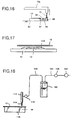
- a method of making a microscope specimen e.g., a tissue slice of an affected part of a patient, is shown in Fig. 17.
- the method comprising the steps of: slicing a tissue of the affected part; mounting the tissue slice 10 onto a slide glass 12; removing fat from the tissue slice 10; dyeing the tissue slice 10; dropping a mounting medium, which includes a solvent, onto the tissue slice 10 on the slide glass 12; and mounting a cover glass 16 onto a mounting medium pattern 140, which is formed by dropping the mounting medium along the tissue slice 10.
- the solvent in the mounting medium evaporates, and the mounting medium solidifies, so that the cover glass 16 is adhered on the slide glass 12.
- a dropping device which automatically drops the mounting medium onto the specimens 10 on the slide glasses 12, was disclosed in the Japanese Patent Gazettes No. 59-157533 and No. 61-66141 .
- compressed air which is compressed by a compressor 102, is introduced into an upper inner space of a container 100, in which the mounting medium including the solvent is reservoired, via a regulator 106 of a pressurizing pipe 104.
- the mounting medium in the container 100 is pushed and sent, by the compressed air in the container 100, to a tank 112 via a spouting pipe 108, whose one end is opened in a lower part of the container 100.
- the mounting medium in the tank 112 is dropped onto the specimen on the slide glass 12 from a drop nozzle 114.
- Amount of dropping the mounting medium can be controlled by a control valve 110, which opens and closes with regular time separations.
- a table 116, on which the slide glass 12 is mounted, is slid in a direction of an arrow, so that the mounting medium can be dropped along the specimen 10 and the mounting medium pattern 140 having the prescribed pattern can be formed.
- the cover glass 16 has a thickness of 0.06-0.25 mm and flat surfaces, so the piled cover glasses 16 are mutually tightly fitted.
- a device for taking out the uppermost cover glass of the piled cover glasses 16 from a holder container was disclosed in the Japanese Patent Gazette No. 58-30636 .
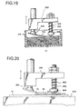
- the device is shown in Fig. 19.
- a press member 204 is pierced through an elevating member 202, which can be moved in the vertical direction, and its lower end 205 is biased downward by a spring 203.
- a sucking pad 206 is provided to the elevating member 202.
- the elevating member 202 is moved downward to push one end of the uppermost glass 16a by the lower end 205 of the press member 204, and the other end of the uppermost glass 16a is pulled upward by the sucking member 206 of the elevating member 202.
- an upper end of the press member 204 is projected upward, against the elasticity of the spring 203, from the elevating member 202.
- the elevating member 202 is moved upward as shown in Fig. 19. With this action, the other end of the cover glass 16a is pulled upward by the sucking member 206, and the cover glass 16a is bent downward, so that the cover glass 16a can be removed from the piled glasses 16 and taken out from the holder container 200.
- the device is shown in Fig. 20.
- a press member 306 is pierced through a holder member 300, which can be moved in the vertical direction, and its lower end 304 is biased downward by a spring 302.
- a sucking pad 308 is provided to the holder member 300.
- the holder member 300 is moved downward and toward the slide glass 12, which has been horizontally mounted on a table 310, until the other end of the cover glass 16 contacts an upper face of one end of the slide glass 12. With further moving the holder member 300 downward, the one end of the cover glass 16 is gradually moved toward the upper face of the slide glass 12. With this action, the cover glass 16 pushes the mounting medium pattern 140 toward the other end of the slide glass 12 and tightly fits thereon, so that air bubbles between the slide glass 12 and the cover glass 16 can be pushed out by the cover glass 16.
- the sucking pad 308 releases the cover glass 16 and the holder member 300 is moved upward, so that the cover glass 12 can be left on the slide glass 12.
- the inventors of the present invention have studied a cover glass adhering device, which includes a unit for taking out the cover glass and a unit for mounting the cover glass, so as to automatically make a microscope specimen.
- the sequential steps for adhering the cover glass onto a specimen on a slide glass can be executed automatically.
- the cover glass adhering device has following disadvantages: it is difficult to always drop fixed amount of mounting medium onto the specimen; it is difficult to always form a mounting medium pattern into a prescribed pattern; the device must be large in size; and a long cover glass cannot be used.
- the size of the device can be smaller than that of the conventional device, in which the slide glass is slid, by sliding a drop nozzle; and fixed amount of the mounting medium can be supplied by using a proper supply unit for supplying fixed amount of the mounting medium, e.g., a plunger pump, and removing a drop of the mounting medium dangling from said drop nozzle.
- a proper supply unit for supplying fixed amount of the mounting medium, e.g., a plunger pump, and removing a drop of the mounting medium dangling from said drop nozzle.
- mounting medium patterns can be always formed into a prescribed pattern by the steps of: stopping a movement of the drop nozzle at a position, at which the drop action of the mounting medium is begun; beginning the drop action thereof; and moving the drop nozzle along the slide glass.
- a rotational angle of a holding member which holds one end of the uppermost cover glass of a plurality of cover glasses, can be made narrower by slantingly piling the cover glasses in a holder container.
- the cover glass adhering device of the present invention which mounts a cover glass onto a mounting medium covering a microscope specimen on a slide glass, comprises:
- cover glass adhering device further includes:
- cover glass adhering device of the present invention preferably includes:
- the traveling unit may include:
- the cover glass adhering device may further comprise a container, in which a solvent for preventing solidification of the mounting medium is reservoired, being located at a position, which is outside of the slide glass and at which a front end of the drop nozzle can enter the container.
- control section of the dropping means may control the movement of the traveling unit so as to put the front end of the drop nozzle into a container, in which a solvent for preventing solidification of the mounting medium is reservoired, before dropping the mounting medium, while stopping or after the dropping action.
- the cover glass supplying means may include, as said holding member, a sucking member being capable of sucking the one end of the uppermost glass of the cover glasses, which have been slantingly piled in the holder container; and may further include:
- control section of the dropping means may control the traveling unit and the supply unit so as to stop the travel of the drop nozzle, which is moved along the slide glass, after stopping the drop action.
- a supporting section of the rack, in which the slide glasses are accommodated may have a inclined face, with which side faces of the slide glasses come into contact.
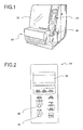
- the cover glass adhering device of the present embodiment of the present invention is shown in Fig. 1.
- the cover glass adhering device has a transparent cover 22 for opening and closing a body section 20, and the body section 20 has an operating panel 24. Further, a container 26, in which mounting medium is reservoired, is inserted in the body section 20. As shown in Fig. 2, a screen 28, on which operating conditions are shown, start and stop buttons for each operation, a check button, etc. are provided in the operating panel 24.
- An adjusting dial 30 for adjusting amount of supplying the mounting medium and a speed adjusting dial 32 for adjusting speed of mounting the cover glasses are also provided in the operating panel 24.
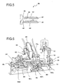
- a basket container 34 in which a plurality of slide glasses on each of which a specimen is mounted are accommodated, and racks 36, which store the slide glasses on each of which the cover glass is adhered, are provided in the body section 20 shown in Fig. 1.
- a plurality of baskets 38 in each of which a plurality of the slide glasses on which the specimens are mounted are vertically stored, are provided in the basket container 34.
- the basket container 34 can be moved by a wire 42, which is driven by a motor 40.
- the racks 36 are capable of moving in the vertical direction, by a motor 37, so as to store the slide glasses in order.
- supporting sections 44 which support both ends of the slide glasses 12, are formed in slide glass accommodating sections of the racks 36. Front ends 46 of the supporting sections 44 are formed into an L-shape so as to prevent the slide glasses 12 from falling down. Further, inner parts 48 of the supporting sections 44 are slopes.
- a conveying means 60 which intermittently conveys the slide glasses 12, which is taken from the basket 38 by slide glass take-out means 50, to the racks 36, is provided between the basket container 34 and the racks 36.
- the slide glass take-out means 50 includes: a motor 54 for vertically moving a member 53, to which a sucking pad 52 for sucking one end of the slide glass 12, which has been vertically stored in the basket 38, is fixed; and a weight 56.
- a guide rod 55 which is guided by a guide groove 57 formed in an inner face of the body section 20, is provided to the member 53 so as to rotate the sucking pad 52.
- the sucking pad 52 is rotated so as to horizontally arrange the slide glass 12, whose one end has been sucked by the sucking pad 52 and vertically pulled upward.
- sucking pad 52 is connected to one end of a hose whose the other end is connected to vacuum means.
- the slide glass 12 which has been horizontally arranged, is located in the vicinity of the take-out means 50, then mounted onto a recessed first station 62a of a supporting member 62, which is capable of supporting both ends of the slide glass 12.
- a recessed second station 62b, a recessed third station 62c and a recessed fourth station 62d are further formed, toward the racks 36, with regular separations.
- the slide glass 12 which is horizontally mounted on the first station 62a is conveyed to the second station 62b, the third station 62c and the fourth station 62d, in order, by a conveying plate 64 of the conveying means 60.
- a plurality of recesses 64a are formed in an upper face of the conveying plate 64 and arranged from the take-out means 50 side to the racks 36 side.
- a projected section 65 is downwardly projected from a bottom face of the conveying plate 64.
- the projected section 65 is connected to a belt 69, which is engaged with a pulley 67, which is directly driven by a motor 66, and free pulleys 68a, 68b and 68c.
- the projected section 65 is vertically moved by a cam 71, which is driven by a motor 70.
- the motors 37, 40, 54, 66 and 70 are controlled by a control section 1.
- the slide glass 12 which has been horizontally mounted on the first station 62a by the take-out means 50, is moved to a position above the supporting member 62 by the conveying plate 64, and the slide glass 12 is horizontally conveyed, in the same state, to a position above the second station 62a, then the slide glass 12 is moved downward, by the conveying plate 64, so that the slide glass 12 can be horizontally mounted on the second station 62b.
- the conveying plate 64 which has been moved downward, is horizontally moved toward the first station 62a so as to convey the next slide glass 12.
- the slide glass 12 can be conveyed to the rest stations and stored in the racks 36 in order.
- the second station 62b is located in the vicinity of a drop nozzle 72 for dropping the mounting medium; the third station 62c is located in the vicinity of a sucking pad 90 for sucking the cover glass.
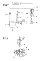
- means for dropping the mounting medium includes: the drop nozzle 72; a connecting member 73a, whose one end is connected to the drop nozzle 72; a motor 73, which constitutes a slide unit for horizontally sliding the drop nozzle 72 and which is connected to the other end of the connecting member 73a; and a solenoid 74, which constitutes an elevating unit for vertically moving the drop nozzle 72 and whose rod 74a is connected to a mid part of the connecting member 73a.
- the motor 73 and the solenoid 74 are controlled by a control section 2.
- the control section 2 moves the drop nozzle 72 in the horizontal direction and the vertical direction.
- a plunger pump 76 which is an example of a supply unit for supplying fixed amount of the mounting medium, supplies the mounting medium from the container 26 to the drop nozzle 72.
- a motor 76b for moving a plunger 76a of the plunger pump 76 is also controlled by the control section 2.
- the drop nozzle 72 is capable of dropping the mounting medium onto the slide glass 12, which has been horizontally arranged, by horizontally moving in the longitudinal direction of the slide glass 12.
- the plunger pump 76 is capable of always supplying the fixed amount of the mounting medium.
- the drop nozzle 72 shown in Fig. 6 is capable of horizontally moving to a position outside of the slide glass 12.
- a discharge tray 78 and a container 80, in which a solvent for preventing solidification of the mounting medium is reservoired, are located at positions, which are outside of the slide glass 12 and within a moving range of the drop nozzle 72.
- a removing member 82 which is capable of removing a drop of the mounting medium dangling from the drop nozzle 72, is vertically extended from the discharge tray 78.
- Check valves 75 and 77 which are capable of preventing reverse flow of the mounting medium, are provided to mid positions of a tube between the container 26 and the drop nozzle 72.
- a sucking pad 90 for sucking the cover glass and a holder container 84, in which a plurality of cover glasses 16 are piled, are provided in the vicinity of the third station 62c.
- the holder container 84 is mounted on a container table 85, which is capable of horizontally rotating.
- the cover glasses 16 are slantingly piled in the holder container 84.
- the uppermost cover glass 16a is taken out from the holder container 84 by the sucking pad 90, which acts as a holding member.
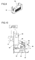
- the sucking pad 90 constitutes means for holding and adhering the cover glass 16 (see Fig. 10).
- the holding-and-adhering means further includes: an arm 86 in which the sucking pad 90 is provided to one end; a motor 87 for rotating the arm 86 about an axis 86a; and a motor 89 for vertically moving an arm member 88, to which the arm 86 is attached. Further, the arm member 88 has a pin 92, which is provided in the vicinity of the sucking pad 90.
- the motors 87 and 89 are controlled by a control section 3.
- sucking pad 90 is connected to one end of a hose whose the other end is connected to the vacuum means.
- the slide glass 12 which is horizontally located on the first station 62a, is conveyed to the second station 62b by the conveying plate 64 so as to drop the mounting medium onto a specimen on the slide glass 12.
- This action is controlled by the control section 2, which controls the solenoid 74 and the motors 73 and 76b.
- the drop nozzle 72 drops the mounting medium onto the specimen on the slide glass 12 and is moved, in the longitudinal direction of the slide glass 12, away from the discharge tray 78, which is located outside of the slide glass, by the motor 73, which is provided to the other end of the connecting member 73a whose one end is connected to the drop nozzle 72, and the solenoid 74, which is connected to the mid part of the connecting member 73a (see Fig. 11A).
- the drop nozzle 72 reaches a predetermined position on the slide glass 12, supplying the mounting medium by the plunger pump 76 and the travel of the drop nozzle 72 in the longitudinal direction of the slide glass 12 are stopped. Then the drop nozzle 72 are moved upward and moved toward the discharge tray 78 (Fig. 11B).
- the drop nozzle 72 is moved downward again and moved away from the discharge tray 78 (see Fig. 11C).
- a drop “B" of the mounting medium which is reservoired in the drop nozzle 72, is apt to dangle from a lower end of the drop nozzle 72, which has been stopped. If the drop nozzle 72, which holds the drop “B”, restarts to drop the mounting medium, amount of the mounting medium dropped on the slide glasses 12 are varied. To drop fixed amount of the mounting medium, the lower end of the drop nozzle 72 is passed over the removing member 82, which is vertically extended from the discharge tray 78, so as to make the drop "B” contact the removing member 82 and remove the drop "B” from the drop nozzle 72.
- the drop nozzle 72 After removing the drop "B", the drop nozzle 72 restarts to drop the mounting medium at a predetermined position on the slide glass 12, so that the fixed amount of the mounting medium can be dropped onto the slide glass 12.
- Amount of supplying the mounting medium can be adjusted by the adjusting dial 30 of the operating panel 24 (see Fig. 2).
- the drop "B" of the mounting medium is removed from the lower end of the drop nozzle 72, and the drop action of the drop nozzle 72 is started when the drop nozzle 72 reaches the predetermined position on the slide glass 12.
- the drop action of the drop nozzle 72 and the travel of the drop nozzle 72, in the longitudinal direction of the slide glass 12 are stopped when the drop nozzle 72 reaches another predetermined position on the slide glass 12. Then the drop nozzle 72 is moved upward.
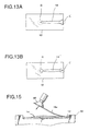
- a mounting medium pattern 14' shown in Fig. 13B is sometimes formed.
- a start end “C” of the pattern 14', at which the drop action is started, is narrow;
- a stop end “D” of the pattern 14', at which the drop action is stopped, is formed like a wide bump.
- the pattern shape shown in Fig.13B air is apt to invade into a space between the cover glass 16 and the slide glass 12 when the cover glass 16 is mounted onto the pattern 14'.
- the pattern 14' is formed. Namely, at the start end "C", the mounting medium is begun to be dropped and traveled simultaneously, so that the shape of the start end "C” is formed narrower.
- the control section 2 controls the solenoid 74 and the motor 73, which move the drop nozzle 72 in the predetermined direction, and the motor 76b, which drives the plunger pump 76 for sending the mounting medium to the drop nozzle 72, so as to execute the steps of: once stopping the travel of the drop nozzle 72 at the start end, at which the mounting medium is begun to be dropped onto the slide glass 12; beginning to drop the mounting medium; and starting to travel the drop nozzle 72 along the surface of the slide glass 12. With this action, the start end "C" of the mounting medium pattern can be wide as shown in Fig. 13A.
- control section 2 controls the solenoid 74 and the motors 73 and 76b so as to stop the travel of the drop nozzle 72 after the drop action is stopped. With this action, the stop end "D" of the mounting medium pattern can be narrower as shown in Fig. 13A.
- the action is controlled by the control section 3, which controls the motors 87 and 89.
- the arm 86 whose one end holds the sucking pad 90, is moved downward by the motor 89 so as to move the sucking pad 90 and the pin 92 toward the cover glasses piled in the holder container 84 (see Fig. 14A).
- the sucking pad 90 sucks and holds one end (lower end) of the uppermost cover glass 16a of the piled cover glasses 16, which have been slantingly piled in the holder container (see Fig. 14B).
- a front end of the pin 92 which is moved downward together with the sucking pad 90, is located above the sucking pad 90 holding the cover glass 16a.
- the arm 86 is turned by the motor 87 (see Fig. 10) to make the other end of the uppermost cover glass 16a contact an inner face of the holder container 84 and bend the uppermost cover glass 16a (see Fig. 14C).
- the one end of the bent cover glass 16a is pressed downward by the pin 92, so that the cover glass 16a is deformed into an S-shape. It is difficult for a long cover glass to peel off from the piled cover glasses by merely bending, but the long cover glass can be easily peeled off by deforming into the S-shape. In the case of using short cover glasses which can be peeled off by merely bending, the pin 92 need not contact the one end of the cover glass.
- the one end of the cover glass 16a which is taken out from the holder container 84, is slantingly held by the sucking pad 90. Then the arm 86 is turned by the motors 87 and 89, so that the other end of the cover glass 16a contacts the upper face of the slide glass 12, which has been mounted on the third station 62c of the supporting member 62, and the one end of the cover glass 16a is gradually moved close to the upper face of the slide glass 12 (see Fig. 15).
- Moving speed of the arm 86 can be controlled by adjusting rotational speed of the motor 87. The rotational speed may be adjusted by the dial 32 of the operating panel 24 (see Fig. 2).
- the moving speed of the arm 86 may be gradually changed, on the basis of characteristics of the mounting medium, speed of dropping the mounting medium, etc., by changing the rotational speed of the motor 87 so as to securely discharge air from the space between the cover glass 16a and the slide glass 12.
- the drop action of the drop nozzle 72 is stopped until the next slide glass 12 is prepared.
- the solvent in the mounting medium volatilizes, so that the mounting medium in the drop nozzle 72 is apt to solidify and close the drop nozzle 72.
- the control section 2 enters the lower end of the drop nozzle 72 into the container 80, which is located outside of the slide glass 12 and within the moving range of the drop nozzle 72 and in which the solvent is reservoired (see Fig. 16). If the drop action is stopped for a short time, the lower end of the drop nozzle 72 may be located in an air space between an entrance of the container 80 and solvent surface so as to prevent the solidification of the mounting medium in the drop nozzle 72.
- the air space is solvent environment.
- the lower end of the drop nozzle 72 should be dipped in the solvent.
- the drop nozzle is left in the air while the drop action is stopped, the mounting medium is apt to solidify. Conventionally, the drop nozzle is manually dipped into the solvent, but this work is troublesome for operators.
- the lower end of the drop nozzle 72 can be automatically entered the solvent container 80.
- the lower end of the drop nozzle 72 is located in the air space between the entrance of the container 80 and the solvent surface so as to prevent the solidification of the mounting medium in the drop nozzle 72.
- the replacement which is required in the conventional drop means, is not required, so that useless cost can be removed and working efficiency can be improved.
- the cover glass adhering device is controlled by the three control sections 1, 2 and 3.
- the cover glass adhering device of the present invention may be controlled by one control section.
- cover glass adhering device of the present invention By using the cover glass adhering device of the present invention, fixed amount of the mounting medium can be always supplied to the slide glasses, the cover glasses having various length can be employed, the device can be small in size, and many microscope specimens can be automatically made for a short time.
- the cover glass adhering device of the present invention may be properly used in hospitals, etc..
Landscapes
- Physics & Mathematics (AREA)
- Life Sciences & Earth Sciences (AREA)
- Analytical Chemistry (AREA)
- General Physics & Mathematics (AREA)
- Chemical & Material Sciences (AREA)
- Health & Medical Sciences (AREA)
- Biomedical Technology (AREA)
- Engineering & Computer Science (AREA)
- Optics & Photonics (AREA)
- Molecular Biology (AREA)
- Biochemistry (AREA)
- General Health & Medical Sciences (AREA)
- Immunology (AREA)
- Pathology (AREA)
- Microscoopes, Condenser (AREA)
- Sampling And Sample Adjustment (AREA)
Claims (13)
- Deckglasanbringungsvorrichtung, die ein Deckglas (16) auf einem Anbringungsmittel anbringt, das eine Mikroskopprobe (10) auf einem Objektglas (12) abdeckt,
gekennzeichnet durch
ein Stützelement (62), das eine Anbringungsmittelaufbringstation (62b) bereitstellt, an der ein Objektglas (12) horizontal haltbar ist,
eine Tropfdüse (72) zum Auftropfen des Anbringungsmittels auf eine Probe (10) auf einem Objektglas (12), wenn das Objektglas horizontal an der Station (62b) gehalten wird,
ein Entfernungselement (82) zum Entfernen eines Tropfens (B) des Anbringungsmittels, der von der Tropfdüse (72) herunterhängt, wobei das Entfernungselement (82) außerhalb des Objektglases (12) angeordnet ist, wenn es an der Station (62b) angeordnet ist, und
eine Bewegungseinheit zum Bewegen der Tropfdüse (72), von der der herunterhängende Tropfen (B) des Anbringungsmittels durch das Entfernungselement (82) entfernt wurde, so dass sie im Betrieb entlang der Probe (10) auf dem an der Station (62b) angeordneten Objektglas (12) vorbeiläuft, so dass eine vorbestimmte Menge des Anbringungsmittels auf die Probe auf getropft wird. - Deckglasanbringungsvorrichtung nach Anspruch 1, bei der die Bewegungseinheit enthält:eine Hebeeinheit zum Bewegen der Tropfdüse (72) in der Vertikalrichtung undeine Schiebeeinheit zum Schieben der Tropfdüse (72) derart, dass sie sich im Betrieb entlang der Probe (10) auf dem an der Station (62b) angeordneten Objektglas (12) zu einer Stellung außerhalb des Objektglases (12) bewegt.
- Deckglasanbringungsvorrichtung nach Anspruch 1 oder 2, die weiter einen Behälter (80) zum Halten eines Lösungsmittels zum Verhindern einer Verfestigung des Anbringungsmittels enthält, wobei der Behälter (80) an einer Stelle angeordnet ist, die außerhalb des Objektglases (12) liegt, wenn es an der Station (62b) angeordnet ist, und die so ist, dass ein vorderes Ende der Tropfdüse (72) in den Behälter (80) eintreten kann.
- Deckglasanbringungsvorrichtung nach einem der Ansprüche 1 bis 3, die weiter einen Steuerabschnitt (2) enthält zum Steuern der Bewegung der Bewegungseinheit derart, dass vor dem Auftropfen des Anbringungsmittels, beim Halten oder nach dem Auftropfvorgang das vordere Ende der Tropfdüse (72) in den Behälter (80) eingeführt wird, in dem ein Lösungsmittel zum Verhindern einer Verfestigung des Anbringungsmittels gehalten ist.
- Deckglasanbringungsvorrichtung nach einem der Ansprüche 1 bis 4, die weiter enthält:einen Haltebehälter (84), der daran angepasst ist, schräg gestapelte Deckgläser (16) zu halten,ein Halteelement (90), das in der Lage ist, ein Ende eines obersten Glases (16a) des Stapels von Deckgläsern (16) zu halten, wenn diese in dem Haltebehälter (84) schräg gestapelt sind,eine Dreheinheit zum Drehen des Halteelements (90), so dass das oberste Glas (16a) abwärts gebogen wird und dass es von dem benachbarten Deckglas (16) entfernt wird, undeine Vertikalantriebseinheit zum vertikalen Bewegen des Halteelements (90) und der Dreheinheit.
- Deckglasanbringungsvorrichtung nach Anspruch 5, die weiter einen Stift (92) enthält, der in der Nähe des Halteelements (90) so bereitgestellt ist, dass der Stift (92) im Betrieb das oberste Deckglas (16a), das abwärts gebogen ist, so drückt, dass er das oberste Deckglas (16a) in eine S-Form verformt.
- Deckglasanbringungsvorrichtung nach Anspruch 1, die weiter enthält:ein Mittel zum Befördern eines Objektglases (12), wobei das Beförderungsmittel (60) bereitgestellt ist zwischen einem Korbbehälter (34), in dem im Betrieb eine Mehrzahl von Objektglä ern (12) untergebracht sind, auf jedem von denen eine Mikroskopprobe (10) angebracht ist, und einem Gestell (36) zum Unterbringen der Objektgläser (12), wenn jedes von ihnen ein Deckglas (16) zum Abdecken der Probe (10) empfangen hat, und das Beförderungsmittel (60) eine Förderplatte (64) aufweist, die im Betrieb intermittierend ein horizontal gehaltenes Objektglas (12) zu dem Gestell befördert,ein Mittel (50) zum Herausnehmen des Objektglases (12) aus dem Korbbehälter (34) und zum horizontalen Auflegen des Objektglases (12) auf eine vorbestimmte Stelle der Förderplatte (64),die Tropfdüse (72), die angeordnet ist zum Auftropfen des Anbringungsmittels auf die Probe (10) auf dem Objektglas (12), das von dem Beförderungsmittel (60) horizontal zu einer vorbestimmten Stelle befördert wurde,eine Zuführeinheit (76), die in der Lage ist, der Tropfdüse (72) eine vorbestimmte Menge des Anbringungsmittels zum Auftropfen auf die Probe (10) zuzuführen,einen Steuerabschnitt (2) zum Steuern der Bewegungseinheit und der Zuführeinheit (76), zum Anhalten der Bewegung der Tropfdüse (72) an einem Startende, an dem die Tropfdüse (72) beginnt, das Anbringungsmittel auf das Objektglas (12) aufzutropfen, und zum Bewegen der Tropfdüse (72) entlang des Objektglases (12) nach dem Beginn des Auftropfens, undein Mittel zum Zuführen des Deckglases (16), das enthält:einen Haltebehälter (84), der im Betrieb schräg gestapelte Deckgläser (16) enthält,ein Halteelement (90), das in der Lage ist, ein Ende eines obersten Glases (16a) des der Deckgläser (16) zu halten, die in dem Haltebehälter (84) schräg gestapelt sind,eine Entnahmeeinheit, die im Betrieb das Halteelement (90) so dreht, dass das oberste Glas (16a) abwärts gebogen wird und dass es von dem benachbarten Deckglas (16) entfernt wird, und dann das oberste Glas (16a) aus dem Haltebehälter (84) herausnimmt, undeine Anbringungseinheit, die im Betrieb das Deckglas (16), dessen eines Ende von dem Halteelement (90) gehalten wird, allmählich von dem anderen Ende bis zu dem einen Ende auf dem Anbringungsmittel anbringt, das die Probe auf dem zu einer vorbestimmten Stelle beförderten Objektglas (12) bedeckt.
- Deckglasanbringungsvorrichtung nach Anspruch 7, bei der ein Stützabschnitt (44) des Gestells (36) eine geneigte Fläche (48) aufweist, die so angeordnet ist, dass Seitenflächen der Objektgläser (12) im Betrieb mit ihr in Kontakt kommen.
- Deckglasanbringungsvorrichtung nach Anspruch 7 oder 8, bei der der Steuerabschnitt (2) des Auftropfmittels die Bewegungseinheit und die Zuführeinheit (76) so steuert, dass die Tropfdüse (72) nach Beenden des Auftropfvorgangs entlang des Objektglases (12) bewegt wird.
- Deckglasanbringungsvorrichtung nach einem der Ansprüche 7 bis 9, bei der die Bewegungseinheit enthält:eine Hebeeinheit zum Bewegen der Tropfdüse (72) in der Vertikalrichtung undeine Schiebeeinheit zum Schieben der Tropfdüse (72) entlang der Probe (10) auf dem Objektglas (12) bis einer Stellung außerhalb des Objektglases (12).
- Deckglasanbringungsvorrichtung nach einem der Ansprüche 7 bis 10, die weiter einen Lösungsmittelbehälter (80) für ein Lösungsmittel zum Verhindern einer Verfestigung des Anbringungsmittels enthält, der an einer Stelle angeordnet ist, die außerhalb des Objektglases (12) liegt, und an der ein vorderes Ende der Tropfdüse (72) in den Behälter (80) eintreten kann.
- Deckglasanbringungsvorrichtung nach Anspruch 11, bei der der Steuerabschnitt (2) des Auftropfmittels daran angepasst ist, die Bewegung der Bewegungseinheit derart zu steuern, dass vor dem Auftropfen des Anbringungsmittels, beim Halten oder nach dem Auftropfvorgang das vordere Ende der Tropfdüse (72) in den Lösungsmittelbehälter (80) eingeführt wird.
- Deckglasanbringungsvorrichtung nach einem der Ansprüche 7 bis 12, bei der
das Halteelement (90) ein Saugelement (90) ist, das in der Lage ist, ein Ende eines obersten Glases (16a) anzusaugen, und
das Deckglaszuführmittel weiter enthält:eine Dreheinheit zum Drehen des Saugelements (90), so dass das andere Ende des obersten Glases (16a) in Kontakt mit einer Innenfläche des Haltebehälters (84) kommt und das oberste Glas (16a) gebogen wird, undeinen Stift, der in der Nähe des Saugelements (90) so bereitgestellt ist, dass der Stift (92) im Betrieb das oberste Deckglas (16a), das gebogen ist, so drückt, dass er das oberste Deckglas (16a) in eine S-Form verformt.
Applications Claiming Priority (2)
| Application Number | Priority Date | Filing Date | Title |
|---|---|---|---|
| JP13034799 | 1999-05-11 | ||
| JP13034799 | 1999-05-11 |
Publications (3)
| Publication Number | Publication Date |
|---|---|
| EP1052497A2 EP1052497A2 (de) | 2000-11-15 |
| EP1052497A3 EP1052497A3 (de) | 2003-01-02 |
| EP1052497B1 true EP1052497B1 (de) | 2007-07-11 |
Family
ID=15032229
Family Applications (1)
| Application Number | Title | Priority Date | Filing Date |
|---|---|---|---|
| EP00303853A Expired - Lifetime EP1052497B1 (de) | 1999-05-11 | 2000-05-08 | Vorrichtung zum Anbringen von Abdeckgläsern |
Country Status (4)
| Country | Link |
|---|---|
| US (1) | US6568447B1 (de) |
| EP (1) | EP1052497B1 (de) |
| JP (1) | JP4659915B2 (de) |
| DE (1) | DE60035452T2 (de) |
Cited By (1)
| Publication number | Priority date | Publication date | Assignee | Title |
|---|---|---|---|---|
| US9528918B2 (en) | 2002-04-15 | 2016-12-27 | Ventana Medical Systems, Inc. | Automated high volume slide processing system |
Families Citing this family (30)
| Publication number | Priority date | Publication date | Assignee | Title |
|---|---|---|---|---|
| US7270785B1 (en) | 2001-11-02 | 2007-09-18 | Ventana Medical Systems, Inc. | Automated molecular pathology apparatus having fixed slide platforms |
| US11249095B2 (en) | 2002-04-15 | 2022-02-15 | Ventana Medical Systems, Inc. | Automated high volume slide processing system |
| WO2003089140A1 (en) | 2002-04-15 | 2003-10-30 | Ventana Medical Systems, Inc. | Automated high volume slide staining system |
| DK1499548T3 (da) | 2002-04-26 | 2008-09-01 | Ventana Med Syst Inc | Fremgangsmåde og apparat til automatiseret pålægning af dækglas |
| EP1499872B1 (de) | 2002-04-26 | 2015-11-18 | Ventana Medical Systems, Inc. | Automatische vorrichtung für molekulare pathologie mit fixierten objektträgerplattformen |
| RU2003106457A (ru) | 2003-02-27 | 2004-11-27 | Иль Борисович Извозчиков (RU) | Устройство для заключения гистологических и биологических образцов (его варианты) |
| JP2005127848A (ja) * | 2003-10-23 | 2005-05-19 | Meisei Electric Co Ltd | 標本封入機のカバーグラス移載装置 |
| JP4008426B2 (ja) * | 2004-04-09 | 2007-11-14 | サクラ精機株式会社 | カバーフィルムの貼着装置 |
| GB2441594B (en) * | 2006-09-08 | 2011-09-07 | Thermo Shandon Ltd | Hopper for storing coverslips |
| DE102007011329A1 (de) * | 2007-03-08 | 2008-09-11 | Medite Gmbh | Verfahren zum Eindecken von auf Objektträgern angeordneten gefärbten histologischen Präparaten |
| CA2742473C (en) | 2008-11-12 | 2015-02-24 | Ventana Medical Systems, Inc. | Methods and apparatuses for heating slides carrying specimens |
| US9498791B2 (en) | 2009-11-13 | 2016-11-22 | Ventana Medical Systems, Inc. | Opposables and automated specimen processing systems with opposables |
| US10746752B2 (en) | 2009-11-13 | 2020-08-18 | Ventana Medical Systems, Inc. | Opposables and automated specimen processing systems with opposables |
| JP5611363B2 (ja) | 2009-11-13 | 2014-10-22 | ベンタナ メディカル システムズ, インコーポレイテッド | 調整可能な体積を収容する薄膜処理装置 |
| DE102011050344B4 (de) * | 2011-05-13 | 2018-10-04 | Leica Biosystems Nussloch Gmbh | Vorrichtung zur Handhabung von Objektträgern mit zwei Eindeckmodulen |
| HU230739B1 (hu) | 2013-02-28 | 2018-01-29 | 3Dhistech Kft. | Berendezés és eljárás tárgylemezek automatikus festésére, fedésére, digitalizálására integrált tárgylemez festő-fedő-digitalizáló automata berendezés segítségével |
| USD728120S1 (en) | 2013-03-15 | 2015-04-28 | Ventana Medical Systems, Inc. | Arcuate member for moving liquids along a microscope slide |
| CN105181426A (zh) * | 2015-10-30 | 2015-12-23 | 广州鸿琪光学仪器科技有限公司 | 吸嘴回收装置及染色机 |
| JP6692252B2 (ja) * | 2016-08-12 | 2020-05-13 | サクラ精機株式会社 | カバースリップ貼着装置 |
| JP7236358B2 (ja) | 2019-09-04 | 2023-03-09 | 平田機工株式会社 | 標本作製装置 |
| WO2021044543A1 (ja) | 2019-09-04 | 2021-03-11 | 平田機工株式会社 | 標本作製装置 |
| CN111579326B (zh) * | 2020-05-29 | 2025-02-28 | 贵州金域医学检验中心有限公司 | 一种组织切片封片设备 |
| CN111579330B (zh) * | 2020-05-29 | 2024-08-27 | 贵州金域医学检验中心有限公司 | 一种封片胶快速固化组织切片封片装置 |
| CN111579327B (zh) * | 2020-05-29 | 2025-05-27 | 贵州金域医学检验中心有限公司 | 一种组织切片自动封片装置 |
| CN111579331B (zh) * | 2020-05-29 | 2024-08-23 | 贵州金域医学检验中心有限公司 | 一种防止封片胶气味外流的组织切片封片设备 |
| CN111579328B (zh) * | 2020-05-29 | 2024-08-23 | 贵州金域医学检验中心有限公司 | 一种防止封片胶气味外流的组织切片封片装置 |
| CN111650016B (zh) * | 2020-05-29 | 2024-08-27 | 贵州金域医学检验中心有限公司 | 一种组织切片封片系统 |
| CN112729983B (zh) * | 2020-12-21 | 2024-09-27 | 广东金泉医疗科技有限公司 | 交联剂滴定喷头移送装置、滴定装置及自动封片设备 |
| CN116358975B (zh) * | 2023-04-14 | 2024-03-19 | 中国人民解放军总医院第三医学中心 | 一种便携式病理玻片自动封片机 |
| CN118033156B (zh) * | 2023-12-29 | 2025-09-02 | 山东骏腾医疗科技有限公司 | 一种胶带式封片机滴液装置 |
Family Cites Families (21)
| Publication number | Priority date | Publication date | Assignee | Title |
|---|---|---|---|---|
| US474267A (en) | 1892-05-03 | Microscopic sediment-filter | ||
| JPS5830636A (ja) | 1981-08-18 | 1983-02-23 | Fujitsu Ltd | 光ファイバ・フォルトロケ−タの測定結果表示方式 |
| JPS5830636U (ja) * | 1981-08-25 | 1983-02-28 | 明星電気株式会社 | 弾性薄板の取り出し装置 |
| US4428793A (en) | 1981-08-25 | 1984-01-31 | Meisei Electric Co., Ltd. | Preparation method for a microscopic specimen and a device therefor |
| JPS58140457U (ja) * | 1982-03-18 | 1983-09-21 | 明星電気株式会社 | 顕微鏡標本作成装置の試料固定機構 |
| JPS5840519A (ja) | 1981-09-03 | 1983-03-09 | Meisei Electric Co Ltd | 顕微鏡用標本の封入方法 |
| JPS5961868A (ja) * | 1982-10-01 | 1984-04-09 | 明星電気株式会社 | 顕微鏡用標本の試料自動封入装置 |
| JPS59157533A (ja) | 1983-02-28 | 1984-09-06 | Sankyo Co Ltd | 液剤射出装置 |
| JPS59157535A (ja) * | 1983-02-28 | 1984-09-06 | Sankyo Co Ltd | 自動標本封入装置 |
| JPS6166141A (ja) | 1984-09-07 | 1986-04-04 | Meisei Electric Co Ltd | プレパラ−ト自動封入装置 |
| JPS62148383U (de) * | 1986-03-14 | 1987-09-19 | ||
| US5000824A (en) | 1987-05-19 | 1991-03-19 | E. I. Du Pont De Nemours And Company | Polyethylene pulp |
| JPH0724344Y2 (ja) * | 1989-06-08 | 1995-06-05 | シャープ株式会社 | 複写機の給紙装置 |
| US5033730A (en) * | 1990-02-28 | 1991-07-23 | Sri International | Variable position vacuum article pickup apparatus |
| JP2523487Y2 (ja) * | 1991-03-18 | 1997-01-22 | 大日本スクリーン製造株式会社 | 回転塗布装置 |
| JP2577067Y2 (ja) * | 1992-03-24 | 1998-07-23 | 株式会社イノアックコーポレーション | 発泡成形用表皮材 |
| JPH06127550A (ja) * | 1992-10-14 | 1994-05-10 | Sakura Seiki Kk | 封入剤容器 |
| JPH06226886A (ja) * | 1993-01-29 | 1994-08-16 | Toshiba Seiki Kk | 糊付装置 |
| AUPN357495A0 (en) * | 1995-06-15 | 1995-07-06 | Australian Biomedical Corporation Limited | Coverslip pick-up and laydown apparatus |
| JP3697315B2 (ja) * | 1996-05-13 | 2005-09-21 | 松下電器産業株式会社 | 接着剤塗布装置 |
| JP3570817B2 (ja) * | 1996-06-04 | 2004-09-29 | 株式会社千代田製作所 | 顕微鏡標本のカバーガラス取出し及び取付け方法 |
-
2000
- 2000-05-05 US US09/565,656 patent/US6568447B1/en not_active Expired - Lifetime
- 2000-05-08 EP EP00303853A patent/EP1052497B1/de not_active Expired - Lifetime
- 2000-05-08 DE DE60035452T patent/DE60035452T2/de not_active Expired - Lifetime
-
2010
- 2010-07-09 JP JP2010156403A patent/JP4659915B2/ja not_active Expired - Fee Related
Cited By (1)
| Publication number | Priority date | Publication date | Assignee | Title |
|---|---|---|---|---|
| US9528918B2 (en) | 2002-04-15 | 2016-12-27 | Ventana Medical Systems, Inc. | Automated high volume slide processing system |
Also Published As
| Publication number | Publication date |
|---|---|
| JP2010217936A (ja) | 2010-09-30 |
| EP1052497A2 (de) | 2000-11-15 |
| EP1052497A3 (de) | 2003-01-02 |
| DE60035452D1 (de) | 2007-08-23 |
| DE60035452T2 (de) | 2008-03-13 |
| US6568447B1 (en) | 2003-05-27 |
| JP4659915B2 (ja) | 2011-03-30 |
Similar Documents
| Publication | Publication Date | Title |
|---|---|---|
| EP1052497B1 (de) | Vorrichtung zum Anbringen von Abdeckgläsern | |
| JP3587470B2 (ja) | 血液の薄層自動作製装置 | |
| JP3694490B2 (ja) | 検体前処理システム | |
| US7767148B2 (en) | Staining/covering system | |
| HK1042551A1 (zh) | 用於將蓋玻片自動附接在顯微鏡載玻片上的機械 | |
| CN101510502B (zh) | 切刀清扫方法、切刀清扫装置及具有它的粘接带粘贴装置 | |
| KR101795612B1 (ko) | 액체 자동 공급 기구 및 이것을 구비하는 도포 장치 | |
| WO1995020176A1 (en) | Instrument for automatically applying coverslips and method | |
| WO2010035582A1 (ja) | 電子部品の実装装置及び実装方法 | |
| JP4709344B2 (ja) | 顕微鏡標本のカバーガラス貼着装置 | |
| EP2290347B1 (de) | Vorrichtung zum befestigen eines deckgläschens | |
| JP5173709B2 (ja) | 電子部品の実装装置及び実装方法 | |
| JP4596501B2 (ja) | 顕微鏡標本のカバーガラス貼着装置 | |
| JP4307487B2 (ja) | 組織標本及び生物学的標本を取り付けるための装置 | |
| JP2011199234A (ja) | 電子部品の実装装置及び実装方法 | |
| CN110534454A (zh) | 液处理装置、液处理方法和计算机可读取的存储介质 | |
| JP4358025B2 (ja) | スライドガラス供給装置およびそれを備える標本作製装置 | |
| US20170274407A1 (en) | Coating Apparatus | |
| JP2010080875A (ja) | 打ち抜き装置、電子部品の実装装置及び実装方法 | |
| JPH0320759Y2 (de) | ||
| JP2005164523A (ja) | 試料吸引分注装置およびそれを備えた標本作製装置 | |
| JPH0472224A (ja) | ケーキ用紙カップの剥離装置 | |
| US3847704A (en) | Apparatus for fabrication price shields or the like consisting of a price tag or label printed by a balance and a label support | |
| JP2005172583A (ja) | 標本作製装置 | |
| JP2005345229A (ja) | 標本作製装置 |
Legal Events
| Date | Code | Title | Description |
|---|---|---|---|
| PUAI | Public reference made under article 153(3) epc to a published international application that has entered the european phase |
Free format text: ORIGINAL CODE: 0009012 |
|
| AK | Designated contracting states |
Kind code of ref document: A2 Designated state(s): AT BE CH CY DE DK ES FI FR GB GR IE IT LI LU MC NL PT SE |
|
| AX | Request for extension of the european patent |
Free format text: AL;LT;LV;MK;RO;SI |
|
| PUAL | Search report despatched |
Free format text: ORIGINAL CODE: 0009013 |
|
| AK | Designated contracting states |
Kind code of ref document: A3 Designated state(s): AT BE CH CY DE DK ES FI FR GB GR IE IT LI LU MC NL PT SE |
|
| AX | Request for extension of the european patent |
Free format text: AL;LT;LV;MK;RO;SI |
|
| 17P | Request for examination filed |
Effective date: 20030319 |
|
| AKX | Designation fees paid |
Designated state(s): DE FR GB |
|
| GRAP | Despatch of communication of intention to grant a patent |
Free format text: ORIGINAL CODE: EPIDOSNIGR1 |
|
| GRAS | Grant fee paid |
Free format text: ORIGINAL CODE: EPIDOSNIGR3 |
|
| RAP1 | Party data changed (applicant data changed or rights of an application transferred) |
Owner name: SAKURA SEIKI CO., LTD |
|
| RAP1 | Party data changed (applicant data changed or rights of an application transferred) |
Owner name: SAKURA SEIKI CO., LTD Owner name: SAKURA FINETEK JAPAN CO., LTD. |
|
| GRAA | (expected) grant |
Free format text: ORIGINAL CODE: 0009210 |
|
| AK | Designated contracting states |
Kind code of ref document: B1 Designated state(s): DE FR GB |
|
| REG | Reference to a national code |
Ref country code: GB Ref legal event code: FG4D |
|
| REF | Corresponds to: |
Ref document number: 60035452 Country of ref document: DE Date of ref document: 20070823 Kind code of ref document: P |
|
| ET | Fr: translation filed | ||
| PLBE | No opposition filed within time limit |
Free format text: ORIGINAL CODE: 0009261 |
|
| STAA | Information on the status of an ep patent application or granted ep patent |
Free format text: STATUS: NO OPPOSITION FILED WITHIN TIME LIMIT |
|
| 26N | No opposition filed |
Effective date: 20080414 |
|
| REG | Reference to a national code |
Ref country code: FR Ref legal event code: PLFP Year of fee payment: 16 |
|
| REG | Reference to a national code |
Ref country code: FR Ref legal event code: PLFP Year of fee payment: 17 |
|
| REG | Reference to a national code |
Ref country code: FR Ref legal event code: PLFP Year of fee payment: 18 |
|
| REG | Reference to a national code |
Ref country code: FR Ref legal event code: PLFP Year of fee payment: 19 |
|
| PGFP | Annual fee paid to national office [announced via postgrant information from national office to epo] |
Ref country code: DE Payment date: 20190430 Year of fee payment: 20 |
|
| PGFP | Annual fee paid to national office [announced via postgrant information from national office to epo] |
Ref country code: FR Payment date: 20190430 Year of fee payment: 20 |
|
| PGFP | Annual fee paid to national office [announced via postgrant information from national office to epo] |
Ref country code: GB Payment date: 20190508 Year of fee payment: 20 |
|
| REG | Reference to a national code |
Ref country code: DE Ref legal event code: R071 Ref document number: 60035452 Country of ref document: DE |
|
| REG | Reference to a national code |
Ref country code: GB Ref legal event code: PE20 Expiry date: 20200507 |
|
| PG25 | Lapsed in a contracting state [announced via postgrant information from national office to epo] |
Ref country code: GB Free format text: LAPSE BECAUSE OF EXPIRATION OF PROTECTION Effective date: 20200507 |