EP1052590A1 - Zwischensockel für Karte - Google Patents
Zwischensockel für Karte Download PDFInfo
- Publication number
- EP1052590A1 EP1052590A1 EP00303374A EP00303374A EP1052590A1 EP 1052590 A1 EP1052590 A1 EP 1052590A1 EP 00303374 A EP00303374 A EP 00303374A EP 00303374 A EP00303374 A EP 00303374A EP 1052590 A1 EP1052590 A1 EP 1052590A1
- Authority
- EP
- European Patent Office
- Prior art keywords
- card
- adaptor
- standard
- connection adaptor
- insertion port
- Prior art date
- Legal status (The legal status is an assumption and is not a legal conclusion. Google has not performed a legal analysis and makes no representation as to the accuracy of the status listed.)
- Granted
Links
Images






Classifications
-
- G—PHYSICS
- G06—COMPUTING OR CALCULATING; COUNTING
- G06F—ELECTRIC DIGITAL DATA PROCESSING
- G06F13/00—Interconnection of, or transfer of information or other signals between, memories, input/output devices or central processing units
- G06F13/10—Program control for peripheral devices
- G06F13/12—Program control for peripheral devices using hardware independent of the central processor, e.g. channel or peripheral processor
-
- G—PHYSICS
- G06—COMPUTING OR CALCULATING; COUNTING
- G06K—GRAPHICAL DATA READING; PRESENTATION OF DATA; RECORD CARRIERS; HANDLING RECORD CARRIERS
- G06K19/00—Record carriers for use with machines and with at least a part designed to carry digital markings
- G06K19/06—Record carriers for use with machines and with at least a part designed to carry digital markings characterised by the kind of the digital marking, e.g. shape, nature, code
- G06K19/067—Record carriers with conductive marks, printed circuits or semiconductor circuit elements, e.g. credit or identity cards also with resonating or responding marks without active components
- G06K19/07—Record carriers with conductive marks, printed circuits or semiconductor circuit elements, e.g. credit or identity cards also with resonating or responding marks without active components with integrated circuit chips
- G06K19/077—Constructional details, e.g. mounting of circuits in the carrier
- G06K19/07737—Constructional details, e.g. mounting of circuits in the carrier the record carrier consisting of two or more mechanically separable parts
- G06K19/07739—Constructional details, e.g. mounting of circuits in the carrier the record carrier consisting of two or more mechanically separable parts comprising a first part capable of functioning as a record carrier on its own and a second part being only functional as a form factor changing part, e.g. SIM cards type ID 0001, removably attached to a regular smart card form factor
-
- G—PHYSICS
- G06—COMPUTING OR CALCULATING; COUNTING
- G06K—GRAPHICAL DATA READING; PRESENTATION OF DATA; RECORD CARRIERS; HANDLING RECORD CARRIERS
- G06K19/00—Record carriers for use with machines and with at least a part designed to carry digital markings
- G06K19/06—Record carriers for use with machines and with at least a part designed to carry digital markings characterised by the kind of the digital marking, e.g. shape, nature, code
- G06K19/067—Record carriers with conductive marks, printed circuits or semiconductor circuit elements, e.g. credit or identity cards also with resonating or responding marks without active components
- G06K19/07—Record carriers with conductive marks, printed circuits or semiconductor circuit elements, e.g. credit or identity cards also with resonating or responding marks without active components with integrated circuit chips
- G06K19/077—Constructional details, e.g. mounting of circuits in the carrier
-
- G—PHYSICS
- G06—COMPUTING OR CALCULATING; COUNTING
- G06K—GRAPHICAL DATA READING; PRESENTATION OF DATA; RECORD CARRIERS; HANDLING RECORD CARRIERS
- G06K7/00—Methods or arrangements for sensing record carriers, e.g. for reading patterns
- G06K7/0013—Methods or arrangements for sensing record carriers, e.g. for reading patterns by galvanic contacts, e.g. card connectors for ISO-7816 compliant smart cards or memory cards, e.g. SD card readers
- G06K7/0021—Methods or arrangements for sensing record carriers, e.g. for reading patterns by galvanic contacts, e.g. card connectors for ISO-7816 compliant smart cards or memory cards, e.g. SD card readers for reading/sensing record carriers having surface contacts
-
- Y—GENERAL TAGGING OF NEW TECHNOLOGICAL DEVELOPMENTS; GENERAL TAGGING OF CROSS-SECTIONAL TECHNOLOGIES SPANNING OVER SEVERAL SECTIONS OF THE IPC; TECHNICAL SUBJECTS COVERED BY FORMER USPC CROSS-REFERENCE ART COLLECTIONS [XRACs] AND DIGESTS
- Y10—TECHNICAL SUBJECTS COVERED BY FORMER USPC
- Y10S—TECHNICAL SUBJECTS COVERED BY FORMER USPC CROSS-REFERENCE ART COLLECTIONS [XRACs] AND DIGESTS
- Y10S439/00—Electrical connectors
- Y10S439/945—Adapter for pcb or cartridge
Definitions
- the present invention relates to a card connection adaptor for connecting an IC card such as a memory card or a functional extension card to an information system such as a personal computer, or a portable information system represented by a PDA (personal digital assistant), a digital still camera and a digital video camera.
- an IC card such as a memory card or a functional extension card
- an information system such as a personal computer, or a portable information system represented by a PDA (personal digital assistant), a digital still camera and a digital video camera.
- PDA personal digital assistant
- Recent notebook PCs are generally equipped with PC card slots. Functional extension of such a notebook PC can be achieved by inserting a PC card into the PC card slot.
- Exemplary PC cards include flash memory cards, modem cards and SCSI cards.
- the PC cards are designed in compliance with the PC Card Standard, and classified into three types which have thicknesses of 3.3 mm (Type I), 5.0 mm (Type II) and 10.5 mm (Type III), respectively, with a rectangular plan shape of 54.0-mm width and 85.6-mm length.
- CF CompactFlash (registered trade mark) cards
- PC cards For smaller-size information systems such as digital cameras, electronic organizers and portable phones, smaller-size CF (CompactFlash (registered trade mark)) cards are employed instead of the PC cards to meet a heavy demand for size reduction.
- CF cards are flash memory cards which are employed to store image data picked up by digital cameras and schedule data and address data for electronic organizers.
- the CF cards are designed in compliance with the CFA (CompactFlash Association) Standard and classified into two types which have thicknesses of 3.3 mm (Type I) and 5.0 mm (Type II), respectively, with a rectangular plan shape of 36.4-mm width and 42.8-mm length.
- CFA CompactFlash Association
- small-size memory cards adapted only for memory functions.
- a small-size memory card includes a memory IC die packaged by resin-sealing, and is characterized by its extremely small thickness.
- Examples of the small-size memorycards include SmartMedia (SM (registered trade mark)), Miniature Card, MemoryStick and MultiMedia Card.
- card connection adaptors are conventionally provided for connecting a CF card or a small-size memory card to a PC card slot.
- Such a card connection adaptor includes a housing having a shape conformal to the PC card, a first connector provided on a front edge of the housing for connection to a PC card slot, and a second connector provided within the housing for connection to a CF card or a small-size memory card.
- a card retaining space for receiving the CF card or the small-size memory card is provided within the housing.
- the card retaining space opens to a rear face of the housing as seen in an insertion direction in which the card connection adaptor is inserted into the PC card slot.
- the card retaining space may also open to the upper and/or lower side of the housing. In any case, the small-size card is inserted into the card connection adaptor from the rear side of the card connection adaptor in the same direction as the adaptor insertion direction in which the card connection adaptor is inserted into the PC card slot.
- connection terminals of the card connection adaptor should accurately be positioned so that connection terminals of the small-size card can be connected to or disconnected from the connection terminals of the card connection adaptor in substantially the same connection/disconnection order and in substantially the same connection/disconnection timing when the small-size card is inserted into or withdrawn from the card connection adaptor.
- connection of a grounding terminal, a source terminal, a first signal terminal, a second terminal and so forth should be established in the order named within an allowable connection timing range. It is, therefore, extremely difficult to design the card connection adaptor which can provide a guarantee against the active insertion and withdrawal.
- the inventors of the present invention proposed a card connection adaptor in Japanese Patent Application No. 11-13333 (1999) (corresponding to US Patent Application No. 09/264,564) previously filed, the card connection adaptor having a card insertion port which opens in a direction generally perpendicular to an adaptor insertion direction in which the card connection adaptor is inserted into a card slot, and adapted to receive the card from the card insertion port.
- the card cannot be inserted into or withdrawn from the card connection adaptor with the card connection adaptor being fitted in the card slot. Therefore, all the aforesaid problems can be solved.
- a housing of the card connection adaptor includes upper and lower covers and a frame.
- the upper and lower covers and the frame are formed with cut-away portions of the same configuration on a face of the housing adjacent to the card insertion port.
- a wiring board formed with signal conversion circuitry for signal conversion between different card standards is retained inwardly of the frame.
- the provision of the cut-away portion in the frame limits the space for provision of circuit components.
- the space for the provision of the circuit components is insufficient even with the use of the smallest circuit components such as a chip-size package.
- the CF card has misinsertion prevention keys provided on side faces thereof along the card insertion direction for preventing the CF card from being inserted into the card slot in a wrong orientation.
- the misinsertion prevention keys should be provided away from the cut-away portion. Therefore, the misinsertion prevention keys have an insufficient length, or the cut-away portion is provided in a limited position.
- a card connection adaptor for connecting a card slot compliant with a predetermined first standard to a card compliant with a second standard which is different from the first standard by fitting the card in the card slot
- the card connection adaptor comprising: a first connector compliant with the first standard for signal transfer to and from the card slot; a second connector compliant with the second standard for signal transfer to and from the card compliant with the second standard; and a card-shaped housing which holds the first connector and the second connector; the housing having first and second covers, a frame held between the first and second covers, a card retaining space defined in the housing for retaining therein the second-standard-compliant card, and a card insertion port provided on one end face thereof and communicating with the card retaining space; the first cover formed with a cut-away portion recessed from the card insertion port in a card insertion direction and having a greater width than the second-standard-compliant card.
- the housing of the card connection adaptor has the first and second covers and the frame.
- the first cover is formed with the cut-away portion having a greater width than the width of the card (which is measured perpendicularly to the card insertion direction in which the card is inserted into the card retaining space). Therefore, when the card is inserted into the card connection adaptor, the card can be inclined upward with respect to the first cover. A front edge of the inclined card is brought into a card insertion space from the cut-away portion, and then the card is oriented generally parallel to the card connection adaptor for insertion of the card into the card retaining space.
- the frame and the second cover have no cut-away portion conformal to the cut-away portion of the first cover adjacent the card insertion port.
- a sufficient space can be reserved for provision of circuit components constituting signal processing circuitry for mutual signal conversion between the first and second standards. Therefore, this arrangement is advantageous for thickness reduction of the card connection adaptor. Since the card retaining space is completely covered with the second cover on one side of the card, the components within the adaptor and the card fitted in the card retaining space can effectively be protected.
- the card retaining space may be defined between the frame and the first cover.
- the adaptor preferably further comprises a guide portion exposed from the cut-away portion for guiding the front edge of the second-standard-compliant card with respect to the card insertion direction toward the card retaining space.
- the guide portion may be a part of the frame or a part of other component such as a wiring board, or may be constructed as a separate component.
- the frame may hold signal conversion circuitry for signal conversion between the first standard and the second standard between the card retaining space and the second cover.
- the frame need not have a cut-away portion, so that a sufficient space can be reserved in the frame to accommodate the circuit components constituting the signal conversion circuitry. This allows for thickness reduction of the card connection adaptor.
- the second cover may have a protector extending to a position opposed to the cut-away portion of the first cover for protection of the inside of the card connection adaptor.
- the card insertion port may open in a direction generally perpendicular to an adaptor insertion direction in which the card connection adaptor is inserted into the card slot.
- the card insertion direction in which the second-standard-compliant card is inserted into the adaptor is generally perpendicular to the adaptor insertion direction.
- the second-standard-compliant card cannot be inserted into and withdrawn from the adaptor along the adaptor insertion direction.
- the card connection adaptor being fitted in the card slot, there is no possibility that the second-standard-compliant card is disconnected from the card connection adaptor, and the second-standard-compliant card cannot be inserted into or withdrawn from the card connection adaptor. Accordingly, an excessively large external force is not needlessly exerted on a connector of the card slot. Since the active insertion and withdrawal of the second-standard-compliant card with respect to the card connection adaptor can be prohibited, there is no need to provide a guarantee against the active insertion and withdrawal. Therefore, the card connection adaptor is easier to design.
- a misinsertion prevention key is preferably provided on an end face of the frame adjacent to the card insertion port for preventing the card connection adaptor from being inserted into the card slot in a wrong orientation.
- the frame need not have a cut-away portion conformal to the cut-away portion of the first cover. Therefore, even where the card insertion port opens perpendicularly to the adaptor insertion direction, the misinsertion prevention key can advantageously be provided on the end face of the frame. Thus, the misinsertion of the card connection adaptor can effectively be prevented.
- the first cover preferably has a fold-back portion formed along an edge thereof defining the cut-away portion by folding back an edge portion thereof into the card retaining space.
- the fold-back portion is preferably provided along an edge of the first cover extending perpendicularly to the card insertion direction.
- This arrangement prevents an user from being injured by the edge of the first cover, and prevents the card inserted into the card retaining space from being damaged by the edge. Since there is no possibility that the card is damaged, the fold-back portion can be utilized as a guide for the insertion of the card. This ensures easier insertion of the card.
- the adaptor preferably further comprises a card lock mechanism to be brought into abutment against a rear edge of the card retained in the card retaining space for prevention of withdrawal of the card.
- the card connection adaptor fitted with the card can more easily be handled. That is, there is no possibility that the card is withdrawn from the adaptor even without any special attention.
- the card lock mechanism may include an abutment portion provided retractably with respect to the card insertion port, and a biasing member for resiliently biasing the abutment portion toward the card insertion port.
- the biasing member may be a coil spring or a plate spring, or may be comprised of a resilient piece formed integrally with the frame. Further, the abutment portion and the biasing member such as the resilient piece may be provided as a unitary member.
- the card lock mechanism may be constructed by utilizing a so-calledearth clip. Although the earth clip is mainly used for connecting the card to an earth terminal of the card slot, the earth clip may be worked to form a plate spring as the biasing member and the abutment portion integral with the plate spring.
- the card lock mechanism may comprise a lock piece having an abutment portion which is manually displaceable in a retractable manner with respect to the card insertion port.
- the card connection adaptor preferably has a card shape conformal to the first-standard-compliant card slot. That is, the housing preferably has substantially the same card-like exterior shape as the first-standard-compliant card. In this case, "the direction generally perpendicular to the adaptor insertion direction" is preferably a direction parallel to upper and lower faces of the card-shaped adaptor.
- the first connector is preferably provided on an end face of the adaptor to be opposed to the connector of the card slot.
- the second connector is preferably provided in a position which allows the second connector to be brought into contact with terminals of the second-standard-compliant card retained in the card. retaining space.
- the card retaining space does not open to the rear side of the adaptor with respect to the adaptor insertion direction. That is, at least the rear side of the adaptor is preferably closed so that the second-standard-compliant card cannot be inserted or withdrawn from the rear side.
- the connector of the card slot is preferably adapted to be contact-connected to the first connector.
- the card slot may be a PC-standard memory card slot.
- the PC-standard memory card slot means a card slot which may commonly be provided in a personal computer. Examples of such a card slot include those which are compliant with the PC Card Standard and the CF Card Standard. These standards stipulate that an input/output control circuit for controlling data input and output be provided in the card. For example, such an input/output control circuit is adapted to control writing and reading of data with respect to a memory IC incorporated in the card.
- the card retaining space is preferably configured so as not to allow the second-standard-compliant card to project outwardly of the card retaining space when the card is retained in the card retaining space.
- the card connection adaptor may further include a wiring board provided within the housing, wherein the first connector, the second connector and the signal conversion circuitry are mounted on the wiring board.
- the housing may include a resin frame and a metal cover which covers the resin frame.
- the signal conversion circuitry may include a pin configuration conversion circuit for converting a pin configuration between a first-standard-compliantcardand the second-standard-compliant card.
- the signal conversion circuitry may include a signal processing circuit for signal conversion between a signal on the first-standard-compliant card and a signal on the second-standard-compliant card to ensure inter-standard compatibility.
- the second-standard-compliant card may be a memory card which incorporates therein a memory IC and has a data storage function.
- the first standard may be a standard which stipulates that the input/output control circuit be provided in the card to be inserted into the card slot.
- the first standard stipulates that the input/output control circuit be present in the card and, therefore, either the card connection adaptor or the second-standard-compliant card should have the input/output control circuit.
- the signal conversion circuitry preferably includes the input/output control circuit.
- Examples of cards designed in compliance with standards which stipulate that the input/output control circuit be present in a card include a PC card, a CF card, a small PC card (SPC with exterior dimensions of 42.8 ⁇ 45 ⁇ 5.0 (mm)).
- the signal conversion circuitry may include an input/output control circuit for performing an input/output control with respect to the second-standard-compliant card.
- the input/output control circuit is provided in the card connection adaptor and, therefore, the second standard may be a standard which stipulates that the input/output control circuit be present in the card slot, or a standard which stipulates that the input/output control circuit be present in the card.
- Examples of cards designed in compliance with standards which stipulate that the input/output control circuit be present in a card slot include SmartMedia, MultiMedia Card, Miniature Card, MemoryStick and SIM (subscriber identity module) cards.
- the card connection adaptor need not have a data input/output control function. Therefore, the signal conversion circuitry may merely include the pin configuration conversion circuit for the conversion of the pin configuration.
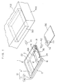
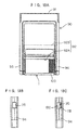
- Fig. 1 is a perspective view illustrating the external construction of a card connection adaptor 1 according to one embodiment of the present invention.
- the card connection adaptor 1 (hereinafter referred to simply as "adaptor 1") has an external shape conformal to a card compliant with the Type-I CF Card Standard (first standard), i.e., a Type-I CF card.
- the adaptor 1 has a card retaining space 2 for retaining therein a card 100 compliant with the MultiMedia Card Standard (second standard), i.e., a MultiMedia card.
- the adaptor 1 can be fitted in a CF card slot 301 provided in an information system 300 such as an electronic organizer for use.
- the adaptor 1 includes a housing 10 which has a card-like exterior shape defined by a resin frame 11 and first and second metal covers 12 and 13 (see Fig. 3) respectively covering upper and lower faces of the frame 11 (in a state as shown in Fig. 1).
- a female connector 21 (first connector) which is to be contact-connected to a male connector 302 provided in the CF card slot 301 is provided on a front face 15 of the housing 10 as shown in Fig. 2.
- the card retaining space 2 formed in the housing 10 has a card insertion port 2A which opens to one side face 16 of the housing adjoining to the face 15. The card retaining space 2 is closed except the side face 16, so that insertion and withdrawal of the card 100 can be achieved only through the card insertion port 2A.
- the card 100 is a generally rectangular thin planar card having a memory IC resin-sealedthereinand a plurality of terminals (seven terminals) 111 exposed on a bottom face thereof.
- the card is dimensioned in compliance with the MultiMedia Card Standard to have a length of 32 mm, a width of 24 mm and a thickness of 1.4 mm.
- the terminals 111 are arranged in a line along a front edge 112 of the card. One corner on the front edge 112 of the card is beveled so as to prevent the card 100 from being inserted into the adaptor in a wrong orientation.
- a card connector (second connector) 22 which is to be electrically connected to the terminals 111 of the card 100 is disposed in the innermost of the card retaining space 2 (as seen from the card insertion port 2A).
- the card 100 is mechanically and electrically connected to the adaptor 1 by inserting the card 100 into the adaptor 1 from the card insertion port 2A.
- the adaptor 1 with this state is inserted into the CF card slot 301 for mechanical and electrical connection thereto, the card 100 is mechanically and electrically connected to the CF card slot 301 via the adaptor 1.
- the slot connector 21 which is to be connected to the CF card slot 301 is provided on the front face 15 to be opposed to the CF card slot 301. Since the card insertion port 2A for insertion of the card 100 is formed on the side face 16, an adaptor insertion direction R1 in which the adaptor 1 is inserted into the CF card slot 301 is perpendicular to a card insertion direction R2 in which the card 100 is inserted into the adaptor 1. Therefore, a rear face 17 of the housing 10 is exposed from the CF card slot 301 with the adaptor 1 fitted in the CF card slot 301. That is, the card retaining space 2 is closed to the outside by the rear face 17.
- the upper metal cover 12 has a rectangular cut-away portion 12A which is recessed from the card insertion port 2A in the card insertion direction R2.
- the cut-away portion 12A has a greater width W than the card 100 as measured perpendicularly to the card insertion direction R2.
- the frame 11 and the lower metal cover 13 are formed with no cut-away portion conformal to the cut-away portion 12A.
- a portion of the metal cover 13 opposed to the cut-away portion 12A serves as a protector for protecting internal circuit components and the inserted card 100 in the cut-away portion 12A.
- the frame 11 includes an upper frame member 11T and a lower frame member 11B joined together (for example, by ultrasonic fusion-bonding), and an inner frame member 11C provided therein.
- the inner frame member 11C has a guide portion 36 exposed from the cut-away portion 12A for guiding a front edge 112 of the card 100 into the card retaining space 2.
- the inner frame member 11C may be provided as a separate member from the upper frame member 11T and the lower frame member 11B, but is formed integrally with the upper frame member 11T in this embodiment.
- the upper frame member 11T is partly cut away adjacent the card insertion port 2A, but the lower frame member 11B have no cut-away portion. Therefore, the frame 11 as a whole has no cut-away portion conformal to the cut-away portion 12A of the metal cover 12.
- a misinsertion prevention key 31 (groove) is provided along a boundary between the upper frame member 11T and the lower frame member 11B on the side face 16 of the frame 11. Since the upper frame member 11T is partly cut away adjacent the card insertion port 2A, only a lower half of the misinsertion prevention key 31 is provided on the lower frame member 11B adjacent the card insertion port 2A. The misinsertion prevention key 31 extends halfway to the card insertion port 2A. With the card 100 being fitted in the card retaining space 2, a rear face of the card 100 serves as part of the misinsertion prevention key.
- a misinsertion prevention key 32 (see Fig. 2) is provided on the opposite side face 18 of the adaptor, but has a width different from the misinsertion prevention key 31 on the side face 16.
- Misinsertion prevention keys (not shown) are respectively provided on opposite side walls of the card slot 301 to be engaged with the misinsertion prevention keys 31 and 32.
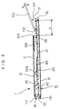
- Fig. 3 is a sectional view of the adaptor taken along a section line extending in the card insertion direction R2
- Fig. 4 is a plan view illustrating the internal construction of the adaptor as seen through the upper metal cover 12.
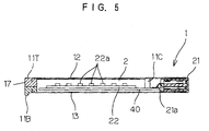
- Fig. 5 is a sectional view taken along a section line V-V in Fig. 4.
- the upper frame member 11T is molded on the metal cover 12 for integration therewith.
- the lower frame member 11B is molded on the metal cover 13 for integration therewith.
- the upper frame member 11T integrated with the metal cover 12 and the lower frame member 11B integrated with the metal cover 13 are joined together by ultrasonic fusion-bonding for formation of the housing 10.
- the cut-away portion 12A of the metal cover 12 is formed by folding back a portion 12B of the metal cover 12. More specifically, the portion of the metal cover 12 folded back toward the card retaining space 2 extends along an edge of the metal cover 12 defining the cut-away portion 12A.
- the fold-back portion can be utilized as a guide for the insertion of the card.
- the upper frame member 11T and the lower frame member 11B define an opening on the front face 15 of the adaptor 1, and the opening serves as a connector fitting portion in which the slot connector 21 is fitted.
- a generally rectangular wiring board 40 is held between the lower metal cover 13 and the inner frame member 11C.
- Leads 21a of the slot connector 21 are soldered on one edge portion of the wiring board 40, whereby the slot connector 21 is mechanically and electrically connected to the wiring board 40. Since the slot connector 21 is retained between the upper and lower metal covers 12 and 13, the one edge of the wiring board 40 is supported via the slot connector 21.
- the card connector 22 is mounted adjacent an edge of the wiring board 40 opposite from the card insertion port 2A.
- the inner frame member 11C has a generally L-shaped support frame portion 35, and the guide portion 36 integrally connected to the support frame portion 35 adjacent the card insertion port 2A.
- the support frame portion 35 has a greater thickness, and has a lower face abutting against the wiring board 40 and an upper face abutting against an interior surface of the upper metal cover 12.
- the guide portion 36 is a thin planar plate extending along the side face 16, and has a greater width than the cut-away portion 12A of the upper metal cover 12.
- the card connector 22 mounted on the wiring board 40 faces to the card retaining space 2 between the support frame portion 35 and the guide portion 36.
- the card retaining space 2 is virtually defined by the lower face of the upper metal cover 12, an interior side wall of the support frame portion 35 of the inner frame member 11C, the upper face of the guide portion 36 of the inner frame member 11, and an upper face of the card connector 22.
- the card connector 22 includes seven terminals 22a corresponding to the seven terminals 111 provided on the bottom face of the card 100.
- the terminals 22a are each comprised of a conductor having a spring-like property.
- the terminals 22a When the card 100 is inserted into the card retaining space 2, the terminals 22a are brought into abutment against the bottom face (the terminals 111 and a resin portion) of the card 100, and resiliently deformed toward the wiring board 40, whereby the insertion of the card 100 in the adaptor is permitted.
- the seven terminals 22a are pressed against the corresponding terminals 111 of the card 100 by their spring force to establish the electrical connection therebetween.
- the seven terminals 22a are connected to circuitry formed on the wiring board 40.
- the front edge 112 of the card 100 to be inserted from the card insertion port 2A is brought into contact with a surface of the guide portion 36.
- the cut-away portion 12A of the upper metal cover 12 is recessed in the card insertion direction R2, and has a greater width than the card 100 as measured perpendicularly to the card insertion direction R2. Therefore, the card 100 can brought into contact with any position within a range ⁇ of the recess of the cut-away portion 12A on the guide portion 36.
- the card 100 may be oriented at any angle with respect to the guide portion, as long as the front edge of the card can be brought into contact with the guide portion 36.
- the card 100 can be handled very easily at the initial stage of the insertion of the card 100 into the card retaining space 2, and there is no need to exactly align the card 100 with the adaptor 1.
- the card 100 is brought into parallel to the metal cover 12 of the adaptor 1 and inserted inward into the card retaining space 2.
- the card 100 can easily be fitted in the adaptor.
- Fig. 6 is a bottom view illustrating the internal construction of the adaptor 1 as seen through the lower metal cover 13.
- Signal conversion circuitry for performing signal conversion between the first standard and the second standard is provided on a lower surface of the wiring board 40 opposite from the card retaining space 2. More specifically, a control IC 41, an EEPROM 42, a power source IC 43, a filtering circuit 44, electrolytic capacitors 45, 46, an oscillator circuit 47, and other circuit elements 48 such as a chip resistor and a chip capacitor are mounted on the wiring board 40 to constitute the signal conversion circuitry. Interconnection conductor lines (not shown) as circuit interconnections are provided on the surface of the wiring board 40.
- ICs such as the control IC 41 and the EEPROM 42 are preferably each comprised of a chip size package IC. Further thickness reduction can be achieved by surface-mounting of the respective circuit components.
- the signal conversion circuitry performs pin configuration conversion between the slot connector 21 compliant with the first standard and the card connector 22 compliant with the second standard, and performs signal processing for signal conversion between these standards.
- the signal conversion circuitry includes an input/output control circuit for controlling data input and output of the card 100 which incorporates therein the memory IC.
- the MultiMedia card and the CF card have a 7-pin configuration and a 50-pin configuration, respectively, with different numbers of pins. Therefore, at least some of signals transferred therebetween should be altered, because the signal conversion cannot be achieved only through the simple pin configuration conversion.
- the frame 11 and the lower metal cover 13 are formed with no cut-away portion, so that the wiring board 40 is allowed to have a greater substrate area.
- a sufficient space can be reserved for provision of the circuit components. This allows for thickness reduction of the adaptor 1 in compliance with the Type-I CF Card Standard.
- the card 100 fitted in the card retaining space 2 is retained in the card retaining space 2 by the resilient force of the terminals 22a of the card connector 22. That is, the terminals 22a come into press contact with the card 100, whereby the card 100 is held between the terminals 22a and the interior surface of the metal cover 12.
- the adaptor 1 can hold the card 100. In consideration of a case where the adaptor 1 fitted with the card 100 is carried around, it is preferred that the adaptor can more assuredly hold the card 100.
- Fig. 7 illustrates a first card lock mechanism 50.
- the card lock mechanism 50 includes a ball 51 (abutment portion) retractably provided as facing to the card insertion port 2A, and a coil spring 52 biasing the ball 51 toward the card insertion port 2A.
- the coil spring 52 is accommodated in a recess 53 formed laterally of the card insertion port 2A in the upper frame member 11T of the frame 11.
- One end of the coil spring 52 is fixed in a boss (not shown) formed in the innermost of the recess 53.
- the ball 51 is fixed to the other end of the coil spring 52 by welding or the like. About half of the ball 51 projects in the card insertion port 2A.
- the ball 51 comes out of the recess 53 by the resilient force of the coil spring 52 to abut against the corner on the rear edge of the card 100.
- a user can get a so-called tactile feedback to clearly recognize that the card 100 has completely been inserted into the adaptor. This prevents incomplete insertion of the card 100 and forcible over-insertion of the card 100, eliminating the possibility of poor contact between the card 100 and the adaptor 1 or breakage of the card connector 22 or the like due to the forcible insertion.
- the recess 53 is formed in the surface of the upper frame member opposed to the lower frame member 11B.
- the coil spring 52 is incorporated in the upper frame member in an unexposed state by joining the upper and lower frame members 11T, 11B together by ultrasonic fusion-bonding after fitting the coil spring 52 in the recess.
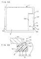
- Figs. 8A and 8B illustrate a second card lock mechanism 55.
- the card lock mechanism 55 includes a plate spring 56 to be resiliently brought into contact with one of the rounded corners on the rear edge of the card 100 inserted in the card retaining space 2.
- the plate spring 56 is press-fitted in a press-fit groove 57 formed in the lower surface of the upper frame member 11T (opposed to the lower frame member 11B). Therefore, most portion of the plate spring is unexposed to the outside after the upper and lower frame members 11T, 11B are joined together by ultrasonic fusion-bonding.
- the plate spring 56 has a fixed portion 56b press-fitted in the press-fit groove 57, a bent linkage portion 56c extending from the fixed portion 56b toward the card insertion port 2A, and an abutment portion 56a curved from the linkage portion 56c as projecting toward the card insertion port 2A.
- the abutment portion 56a projects toward the card insertion port 2A.
- a recess 58 is formed in the upper frame member 11T to communicate with the press-fit groove 57, so that the linkage portion 56c can resiliently be deformed in the recess 58. Thus, the abutment portion 56a can be retracted from the card insertion port 2A.
- the plate spring 56 is resiliently deformed to retract the abutment portion 56a from the card insertion port 2A, whereby the card 100 can be withdrawn from the adaptor.
- This arrangement provides substantially the same effects as the aforesaid first card lock mechanism 50.
- Figs. 9A and 9B illustrate a third card lock mechanism 60.
- the adaptor 1 includes earth clips 61, 62, as shown in Fig. 9A, which are provided on opposite side edges thereof extending in the adaptor insertion direction R1 (see Fig. 1) so as to be brought into contact with earth terminals (not shown) in the card slot 301.
- the earth clips 61, 62 are composed of a conductive material such as stainless steel.
- the earth clip 62 located opposite from the card insertion port 2A is wrapped around the upper frame member 11T and the lower frame member 11B of the frame 11 and connected to the upper and lower metal covers 12, 13.
- the earth clip 61 located adjacent the card insertion port 2A is wrapped around the lower frame member 11B of the frame 11 and connected to the lower metal cover 13. More specifically, the earth clip 61 is formed, for example, by working a stainless steel plate.
- the earth clip 61 includes a connection portion 61A extending inwardly of the lower frame member 11B and connected to the metal cover 13, a generally U-shaped wrap portion 61B extending from the connection portion 61A and wrapped around an edge of the lower frame member 11B, an anchored portion 61C bent at an end of the wrap portion 61B as extending inwardly of the lower frame member 11B, and an abutment portion 61D formed by incising and raising a part of the wrap portion 61B as projecting toward the card insertion port 2A.
- the abutment portion 61D is curved as projecting toward the card insertion port 2A.
- An inclined surface of the abutment portion 61D facing to the card retaining space 2 serves as a restriction surface 63 to be brought into abutment against the rear edge of the inserted card 100 for prevention of the withdrawal of the card 100.
- the other inclined surface of the abutment portion 61D opposite from the card retaining space 2 serves as a guide surface 64 for guiding the card 100 during the insertion of the card toward the card insertion port 2A. Since the card 100 can be brought into angled contact with the adaptor in the cut-away portion 12A of the metal cover 12 when the card 100 is to be inserted into the adaptor 1, the guiding function of the guide surface 64 is not so important.
- a distal end of the abutment portion 61D is directed into an opening 65 formed in the wrap portion 61B by the incision and, therefore, this arrangement advantageously prevents the abutment portion 61D from injuring a user's finger.
- the card lock mechanism 60 having the aforesaid construction provides the same effects as the first and second card lock mechanisms 50, 55.
- the lock mechanism can be provided by utilizing the earth clips which are essential components for a communications card or the like, so that an increase in costs can advantageously be suppressed.
- Fig. 10 illustrates a fourth card lock mechanism 70.
- the card lock mechanism 70 includes a resilient lock piece 71 formed integrally with the upper frame member 11T molded of a resin. More specifically, a groove 72 is formed in a distal end portion of a rear beam 74 of the upper frame member 11T adjacent to the card insertion port 2A, and the resilient lock piece 71 is provided along the groove 72 adjacent the card insertion port 2A. An abutment portion 73 to be brought into abutment against the rear edge of the card 100 is provided at a distal end of the resilient lock piece 71.
- the abutment portion 73 abuts against a side edge of the card 100, so that the resilient lock piece 71 is resiliently deformed thereby to be retracted into the groove 72.
- the resilient lock piece 71 returns to its original position, and the abutment portion 73 abuts against one of the rounded corners on the rear edge of the card 100.
- the card lock mechanism 70 provides the same effects as the first card lock mechanism 50 and the like. Since the card lock mechanism 70 is integral with the frame 11, there is no need for preparation of an additional component. Therefore, this arrangement is advantageous in terms of costs, and allows for easier fabrication of the adaptor 1.
- Figs. 11A and 11B illustrate a fifth card lock mechanism 75.
- the card lock mechanism 75 has a lock beam 76 (lock piece) provided slidably and retractably with respect to the card insertion port 2A.
- the lock beam 76 is slidably engaged with a through-hole 77 which is formed in the lower surface of the upper frame member 11T as extending through the frame 11 perpendicularly to the card insertion direction R2 (see Fig. 1).
- the lock beam 76 has a movement restricting portion 76A formed integrally therewith as projecting from the midportion thereof, and the through-hole 77 has a greater width portion 77A provided at the midportion thereof for permitting the movement restricting portion 76 to slide within a predetermined range.
- the lock beam 76 can slidably be displaced within the predetermined stroke range without disengaging from the frame 11. More specifically, the lock beam 76 can assume a lock state where one end thereof adjacent to the card insertion port 2A projects into the card insertion port 2A by a predetermined length and the other end thereof is retained in the through-hole 77, and an unlock state where the one end thereof adjacent to the card insertion port 2A is retained in the through-hole 77 and the other end thereof projects outwardly of the frame 11. For switching of the lock beam 76 between the lock state and the unlock state, either of the end portions thereof projecting from the through-hole 77 is pressed into the through-hole 77.
- the insertion of the card 100 can easily be achieved with the lock beam 76 being in the unlock state.
- the lock beam 76 is brought into the lock state thereby to assuredly prevent disengagement of the card 100.
- a distal end portion of the lock beam 76 abuts against the rear edge of the card 100.
- a compressive coil spring may be fitted around the lock beam 76 in the greater width portion 77A of the through-hole 77 to bias the lock beam 76 into the lock state.
- the lock beam 76 is prevented fromneedlessly projecting outwardly of the frame 11 for prevention of damage of the lock beam 76.
- Figs. 12A, 12B and 12C illustrate a sixth card lock mechanism 80.
- the card lock mechanism 80 has a slide lock piece 81 incorporated in the frame 11 in a slidable manner.
- the slide lock piece 81 has an operation portion 81A exposed on the rear face 17 of the frame 11 to be slid by an user, and an elongated abutment portion 81B (lock piece) extending from the operation portion 81A to be brought into abutment against the rear edge of the card 100.
- Slide portions 81C slidable along guide grooves (not shown) of the frame 11 are provided integrally with upper and lower faces of the operation portion 81A.
- a curved guide groove 83 of generally L-shape for guiding the abutment portion 81B is formed in the upper frame member 11T.
- the curved guide groove 83 has a portion extending in the direction of sliding of the operation portion 81A, and a portion curved from this portion toward the card insertion port 2A.
- the abutment portion 81B is allowed to assume a lock state where it projects in the card insertion port 2A and an unlock state where it is retracted in the curved guide groove 83.
- At least the abutment portion 81B of the slide lock piece 81 should be composed of a flexible material so as to be deformable in conformity with the shape of the curved guide groove 83.
- An example of the material is nylon.
- Figs. 13A, 13B and 13C are diagrams illustrating the construction of another adaptor 90 suitable for use with the aforesaid card connection adaptor 1.
- Fig. 13A is a plan view of the adaptor 90
- Figs. 13B and 13C are enlarged partial side views of the adaptor 90.
- the adaptor 90 is used for fitting a CF card in a PC card slot for adaptation of the CF card to the PC card slot.
- the adaptor 90 includes a slot connector 91 provided on a front edge thereof for connection to a connector in the PC card slot, and a CF card fitting portion 92 provided on a rear edge thereof.
- the CF card fitting portion 92 has a cut-away portion 92A, and a card connector 92B provided inwardly of the cut-away portion 92A for connection to the CF card.
- a pair of arms 93, 94 define the cut-away portion 92A, and keys (not shown) are provided on interior side walls of the arms 93, 49 for engagement with misinsertion prevention keys provided on opposite side faces of the CF card.
- the adaptor 90 is fitted in the PC card slot with the CF card being fitted in the CF card fitting portion 92, whereby the CF card can electrically be connected to an information system with the use of the PC card slot.
- the aforesaid adaptor 1 can be fitted in the adaptor 90. Therefore, the adaptor 1 fitted with the MultiMedia card 100 is fitted in the adaptor 90, which is in turn inserted into the PC card slot. Thus, the MultiMedia card 100 can electrically be connected to the information system with the use of the PC card slot.
- a through-hole (window) 95 is formed in the arm 94 of the adaptor 90 adjacent to the card insertion port 2A of the adaptor 1 to communicate with a space inside the cut-away portion 92A.
- the through-hole 95 is located in such a position that a side face of the lower frame member 11B of the adaptor 1 and the rear edge of the card 100 retained in the card retaining space 2 can be seen through the through-hole. Therefore, where no card is fitted in the CF card fitting portion 92, a state as shown in Fig. 13B is observed. Where the adaptor 1 retaining therein the card 100 is fitted in the CF card fitting portion 92, a state as shown in Fig. 13C is observed.
- a state where the CF card is retained in the adaptor 90 or a state where the adaptor 1 not fitted with the card 100 is retained in the adaptor 90 can also be observed.
- a window is preferably provided in an externally viewable manner to be associated with the through-hole 95.
- the invention can be embodied in any other ways.
- the card connection adaptor explained in the aforesaid embodiment is designed to adapt the MultiMedia card to the Type-I CF card slot
- the invention is also applicable to conversion between any other different standards. If the card inserted in the adaptor projects rearwardly of the adaptor in the card inserting direction, however, it is impossible to insert the adaptor into the card slot. Therefore, physical limitations may be imposed on combinations of the card standards for use with ordinary card slots.
- Table 1 shows possible combinations of a standard to be employed as the first standard for the card slot and a standard to be employed as the second standard for the card.
- the present invention is applicable to combinations of standards indicated by "o” and is not applicable to combinations of standards indicated by " ⁇ ".
- the advantage of the invention for easier card insertion is also ensured by providing the card insertion port on the rear face of the adaptor with respect to the adaptor insertion direction. More specifically, the card insertion port is provided on the rear face of the adaptor with respect to the adaptor insertion direction, and the cut-away portion having a greater width than the card is formed in the upper cover as recessed in the adaptor insertion direction (which is parallel to the card insertion direction in this case).
- the guide portion 36 is provided on the inner frame member 11C in the embodiment described above, the back surface of the wiring board 40 (opposed to the upper metal cover 12) may serve as a guide for guiding the front edge of the card 100 without the provision of the guide portion 36.
Landscapes
- Engineering & Computer Science (AREA)
- Theoretical Computer Science (AREA)
- Physics & Mathematics (AREA)
- General Physics & Mathematics (AREA)
- Computer Hardware Design (AREA)
- Microelectronics & Electronic Packaging (AREA)
- Artificial Intelligence (AREA)
- Computer Vision & Pattern Recognition (AREA)
- General Engineering & Computer Science (AREA)
- Coupling Device And Connection With Printed Circuit (AREA)
Applications Claiming Priority (2)
| Application Number | Priority Date | Filing Date | Title |
|---|---|---|---|
| JP11681499 | 1999-04-23 | ||
| JP11116814A JP2000305662A (ja) | 1999-04-23 | 1999-04-23 | カード接続用アダプタ |
Publications (2)
| Publication Number | Publication Date |
|---|---|
| EP1052590A1 true EP1052590A1 (de) | 2000-11-15 |
| EP1052590B1 EP1052590B1 (de) | 2007-08-29 |
Family
ID=14696314
Family Applications (1)
| Application Number | Title | Priority Date | Filing Date |
|---|---|---|---|
| EP00303374A Expired - Lifetime EP1052590B1 (de) | 1999-04-23 | 2000-04-20 | Zwischensockel für Karte |
Country Status (7)
| Country | Link |
|---|---|
| US (1) | US6264506B1 (de) |
| EP (1) | EP1052590B1 (de) |
| JP (1) | JP2000305662A (de) |
| KR (1) | KR100694604B1 (de) |
| CN (1) | CN1189985C (de) |
| DE (1) | DE60036153T2 (de) |
| TW (1) | TW448593B (de) |
Cited By (11)
| Publication number | Priority date | Publication date | Assignee | Title |
|---|---|---|---|---|
| WO2002089039A1 (en) * | 2001-04-27 | 2002-11-07 | Sierra Wireless, Inc. | Module interface for pc card |
| FR2832830A1 (fr) * | 2001-11-28 | 2003-05-30 | At Sky | Lecteur de cartes a puce avec insertion securisee d'une ou plusieurs cartes |
| WO2003100720A1 (en) * | 2002-05-24 | 2003-12-04 | Docomo Communications Laboratories Europe Gmbh | Chip card of reduced size with backward compatibility and adapter for a reduced size chip card |
| WO2004040714A1 (en) * | 2002-10-25 | 2004-05-13 | Molex Incorporated | Memory card adapter for connecting a miniature card to a standard card connector, along with a method of fabricating same |
| FR2848346A1 (fr) * | 2002-12-05 | 2004-06-11 | Gemplus Card Int | Adaptateur pour la connexion electrique d'une mini-carte a circuits(s)integre(s)dans un connecteur pour carte a memoire |
| EP1441302A3 (de) * | 2003-01-22 | 2005-11-23 | Fujitsu Limited | Konvertierungsvorrichtung |
| FR2881310A1 (fr) * | 2005-01-25 | 2006-07-28 | Julien Lageois | Porte-carte d'identification sim pour les telephones portables |
| EP1760627A3 (de) * | 2005-08-30 | 2007-05-23 | Matsushita Electric Works, Ltd. | Speicherkartensockel |
| EP1933422A3 (de) * | 2006-12-15 | 2009-04-29 | Hosiden Corporation | Kartenadapter |
| DE10141873B4 (de) * | 2001-08-28 | 2010-01-28 | Carry Computer Eng. Co., Ltd., Hsin-Tien | Schreib-/Lesegerät für Speicherkarten |
| US11763105B2 (en) | 2018-10-16 | 2023-09-19 | Huawei Technologies Co., Ltd. | Memory card, memory card adapter, and terminal device |
Families Citing this family (89)
| Publication number | Priority date | Publication date | Assignee | Title |
|---|---|---|---|---|
| US6230006B1 (en) | 1997-09-08 | 2001-05-08 | Acterna, Llc | Test system for remotely testing switches within a telecommunications network |
| FR2773900B1 (fr) * | 1998-01-22 | 2000-02-18 | Gemplus Card Int | Carte a circuit(s) integre(s) a contact, comportant une minicarte detachable |
| US7020441B2 (en) * | 1998-09-03 | 2006-03-28 | Casabyte, Inc. | Test system for remotely testing switches within a telecommunications network |
| JP3250986B2 (ja) * | 1999-01-21 | 2002-01-28 | 日本圧着端子製造株式会社 | カード接続用アダプタ |
| FI107973B (fi) * | 1999-03-11 | 2001-10-31 | Nokia Mobile Phones Ltd | Menetelmä ja välineet lisäkorttien käyttämiseksi matkaviestimessä |
| US7227742B2 (en) * | 1999-06-17 | 2007-06-05 | Lenovo (Singapore) Pte. Ltd. | System for organizing one or more personal computer accessory devices |
| US20080278903A1 (en) * | 2000-01-06 | 2008-11-13 | Super Talent Electronics, Inc. | Package and Manufacturing Method for Multi-Level Cell Multi-Media Card |
| JP2001236778A (ja) * | 2000-02-24 | 2001-08-31 | Mitsumi Electric Co Ltd | カード型メモリ用fd型アダプタ |
| US20030084220A1 (en) * | 2001-11-01 | 2003-05-01 | Jones Larry Lawson | Active adapter chip for use in a flash card reader |
| US6438638B1 (en) * | 2000-07-06 | 2002-08-20 | Onspec Electronic, Inc. | Flashtoaster for reading several types of flash-memory cards with or without a PC |
| US7093161B1 (en) * | 2002-08-16 | 2006-08-15 | Onspec Electronic, Inc. | Software recovery method for flash media with defective formatting |
| US7252240B1 (en) | 2000-07-06 | 2007-08-07 | Onspec Electronics, Inc. | Memory module which includes a form factor connector |
| US7493437B1 (en) * | 2000-07-06 | 2009-02-17 | Mcm Portfolio Llc | Flashtoaster for reading several types of flash memory cards with or without a PC |
| US7278051B2 (en) * | 2000-07-06 | 2007-10-02 | Onspec Electronic, Inc. | Field-operable, stand-alone apparatus for media recovery and regeneration |
| US7295443B2 (en) * | 2000-07-06 | 2007-11-13 | Onspec Electronic, Inc. | Smartconnect universal flash media card adapters |
| JP4759826B2 (ja) * | 2000-11-10 | 2011-08-31 | ソニー株式会社 | アダプタ装置及びメモリ装置 |
| CN101004944A (zh) * | 2001-04-02 | 2007-07-25 | 株式会社日立制作所 | 存储卡 |
| US20030085288A1 (en) * | 2001-11-06 | 2003-05-08 | Luu Deniel V.H. | Contactless SIM card carrier with detachable antenna and carrier therefore |
| TW544976B (en) * | 2002-02-06 | 2003-08-01 | High Tech Comp Corp | Expansion card adapting device of portable electronic product |
| US20030172295A1 (en) * | 2002-03-01 | 2003-09-11 | Onspec Electronics, Inc. | Device and system for allowing secure identification of an individual when accessing information and a method of use |
| US6789164B2 (en) * | 2002-03-14 | 2004-09-07 | Behavior Tech Computer Corporation | Method for directly writing data into optic disk |
| US6524137B1 (en) * | 2002-03-15 | 2003-02-25 | Carry Computer Eng. Co., Ltd. | Integral multiplex adapter card |
| US20030212616A1 (en) * | 2002-05-09 | 2003-11-13 | Casabyte, Inc. | Method, apparatus and article to remotely associate wireless communications devices with subscriber identities and/or proxy wireless communications devices |
| US6736678B2 (en) * | 2002-06-26 | 2004-05-18 | Li-Ho Yao | Memory card interface adapter |
| JP3784783B2 (ja) * | 2002-07-03 | 2006-06-14 | 山一電機株式会社 | カードコネクタ |
| US6865086B2 (en) * | 2002-07-09 | 2005-03-08 | Micron Technology, Inc. | Apparatus and method to secure an adaptor to a reduced-sized memory card |
| TW564969U (en) * | 2002-07-24 | 2003-12-01 | Via Tech Inc | Voltage conversion card on a motherboard |
| JP2004070435A (ja) * | 2002-08-01 | 2004-03-04 | Toshiba Corp | カード処理装置 |
| JP4019965B2 (ja) * | 2003-02-10 | 2007-12-12 | ソニー株式会社 | Icカードのアダプタ装置 |
| US6805589B2 (en) * | 2003-02-14 | 2004-10-19 | Super Link Electronics Co., Ltd. | Memory card socket with drawer-type cartridge seat |
| JP4237535B2 (ja) * | 2003-04-24 | 2009-03-11 | 山一電機株式会社 | インタフェース装置 |
| TWM251307U (en) * | 2003-09-12 | 2004-11-21 | Hon Hai Prec Ind Co Ltd | Card connector |
| JP4141362B2 (ja) * | 2003-09-29 | 2008-08-27 | アルプス電気株式会社 | カードアダプタ |
| JP2005243277A (ja) * | 2004-02-24 | 2005-09-08 | Alps Electric Co Ltd | カード用アダプタ |
| CN100369057C (zh) * | 2004-02-24 | 2008-02-13 | 阿尔卑斯电气株式会社 | 卡用转接器 |
| US7513801B2 (en) * | 2004-04-28 | 2009-04-07 | C-One Technology Corporation | Apparatus with detachably connected memory-card type adapter |
| JP4661137B2 (ja) | 2004-09-01 | 2011-03-30 | 船井電機株式会社 | 電気機器および複合プリンタ装置 |
| TWM267704U (en) * | 2004-11-23 | 2005-06-11 | Tai Sol Electronics Co Ltd | Card connector having function of preventing from erroneous insertion |
| US20060121941A1 (en) * | 2004-12-03 | 2006-06-08 | Shiflett Jamie C | SIM card retaining device |
| US20060203733A1 (en) * | 2005-02-17 | 2006-09-14 | Casabyte, Inc. | Methods, apparatuses, and articles to remotely test communications networks using digital fingerprints of content |
| JP2006318217A (ja) * | 2005-05-12 | 2006-11-24 | Matsushita Electric Works Ltd | メモリカード用アダプタ |
| US7052290B1 (en) * | 2005-08-10 | 2006-05-30 | Sony Ericsson Mobile Communications Ab | Low profile connector for electronic interface modules |
| JP2007053490A (ja) * | 2005-08-16 | 2007-03-01 | Fujifilm Corp | 可換型撮像素子ユニット、カメラ本体、カメラシステム |
| US7907366B2 (en) * | 2005-10-25 | 2011-03-15 | Prostor Systems, Inc. | Removable data cartridge |
| US20070162626A1 (en) * | 2005-11-02 | 2007-07-12 | Iyer Sree M | System and method for enhancing external storage |
| US7876894B2 (en) * | 2006-11-14 | 2011-01-25 | Mcm Portfolio Llc | Method and system to provide security implementation for storage devices |
| US7798840B2 (en) * | 2007-01-05 | 2010-09-21 | Sandisk Corporation | Expandable and collapsible peripheral device |
| US20080181406A1 (en) * | 2007-01-30 | 2008-07-31 | Technology Properties Limited | System and Method of Storage Device Data Encryption and Data Access Via a Hardware Key |
| US20080288782A1 (en) * | 2007-05-18 | 2008-11-20 | Technology Properties Limited | Method and Apparatus of Providing Security to an External Attachment Device |
| US20080184035A1 (en) * | 2007-01-30 | 2008-07-31 | Technology Properties Limited | System and Method of Storage Device Data Encryption and Data Access |
| US20090046858A1 (en) * | 2007-03-21 | 2009-02-19 | Technology Properties Limited | System and Method of Data Encryption and Data Access of a Set of Storage Devices via a Hardware Key |
| US20080195814A1 (en) * | 2007-02-08 | 2008-08-14 | Heisei Electronics Co., Ltd. | Multi-functional storage device |
| US20080225494A1 (en) * | 2007-03-13 | 2008-09-18 | Chih-Yi Yang | Solid-state hard disk drive |
| US20080288703A1 (en) * | 2007-05-18 | 2008-11-20 | Technology Properties Limited | Method and Apparatus of Providing Power to an External Attachment Device via a Computing Device |
| US7572152B2 (en) * | 2007-06-27 | 2009-08-11 | Sandisk Il Ltd. | Memory interface card with SIM functions |
| US7779184B2 (en) * | 2007-06-29 | 2010-08-17 | Sandisk Corporation | Method of using the dual bus interface in an expresscard slot |
| US7780477B2 (en) * | 2007-06-29 | 2010-08-24 | Sandisk Corporation | Adapter system for use with an expresscard slot |
| US8051229B2 (en) * | 2007-06-29 | 2011-11-01 | Sandisk Technologies Inc. | Dual bus ExpressCard peripheral device |
| US7699660B2 (en) * | 2007-06-29 | 2010-04-20 | Sandisk Corporation | Adapter for an expresscard slot |
| US8561295B2 (en) * | 2007-06-29 | 2013-10-22 | Sandisk Technologies Inc. | Method of adapting an expresscard slot for smaller form factor memory compatibility |
| US7686654B2 (en) * | 2007-06-29 | 2010-03-30 | Sandisk Corporation | Memory card for an ExpressCard slot |
| US20090172235A1 (en) * | 2007-12-27 | 2009-07-02 | Mei Yan | Megasim card adapter |
| JP4726922B2 (ja) * | 2008-02-28 | 2011-07-20 | シナノケンシ株式会社 | 記憶媒体の誤挿入防止部材、記憶媒体の誤挿入防止システム及び記憶媒体の誤挿入防止部材の固定方法 |
| US20100315774A1 (en) * | 2008-03-07 | 2010-12-16 | Walker Paul N | Wireless Card Adapters |
| US8164908B2 (en) * | 2008-07-29 | 2012-04-24 | Panasonic Corporation | Protector for plate-like peripheral device of electronic equipment |
| KR20100030126A (ko) * | 2008-09-09 | 2010-03-18 | 삼성전자주식회사 | 메모리 장치 및 그를 포함하는 전자 장치 |
| US8070522B2 (en) | 2008-12-12 | 2011-12-06 | Cisco Technology, Inc. | Adaptor for a router blade |
| USD794644S1 (en) * | 2009-01-07 | 2017-08-15 | Samsung Electronics Co., Ltd. | Memory device |
| USD795261S1 (en) * | 2009-01-07 | 2017-08-22 | Samsung Electronics Co., Ltd. | Memory device |
| USD794643S1 (en) * | 2009-01-07 | 2017-08-15 | Samsung Electronics Co., Ltd. | Memory device |
| USD794034S1 (en) * | 2009-01-07 | 2017-08-08 | Samsung Electronics Co., Ltd. | Memory device |
| USD794641S1 (en) * | 2009-01-07 | 2017-08-15 | Samsung Electronics Co., Ltd. | Memory device |
| USD795262S1 (en) * | 2009-01-07 | 2017-08-22 | Samsung Electronics Co., Ltd. | Memory device |
| USD794642S1 (en) * | 2009-01-07 | 2017-08-15 | Samsung Electronics Co., Ltd. | Memory device |
| US8325486B2 (en) * | 2009-01-13 | 2012-12-04 | Dy 4 Systems Inc. | Tamper respondent module |
| TWM370233U (en) * | 2009-05-12 | 2009-12-01 | Hon Hai Prec Ind Co Ltd | Electrical connector assembly |
| CN102005675B (zh) * | 2009-08-31 | 2014-03-05 | 深圳富泰宏精密工业有限公司 | 卡固持结构 |
| USD669478S1 (en) * | 2012-01-13 | 2012-10-23 | Research In Motion Limited | Device smart card |
| USD669479S1 (en) * | 2012-01-13 | 2012-10-23 | Research In Motion Limited | Device smart card |
| US8654535B2 (en) * | 2012-03-08 | 2014-02-18 | Proconn Technology Co., Ltd. | Card holder |
| JP5549821B2 (ja) * | 2012-04-17 | 2014-07-16 | 第一精工株式会社 | 電気コネクタ |
| CN202749602U (zh) * | 2012-06-19 | 2013-02-20 | 深圳富泰宏精密工业有限公司 | 芯片卡固持结构及具有该芯片卡固持结构的电子装置 |
| CN104200256B (zh) * | 2014-08-28 | 2017-01-18 | 绵阳市绵州通有限责任公司 | 一种公交卡 |
| JP6253607B2 (ja) * | 2015-03-16 | 2017-12-27 | 東芝メモリ株式会社 | 半導体メモリカードの製造方法 |
| JP6613130B2 (ja) * | 2015-12-22 | 2019-11-27 | モレックス エルエルシー | カード保持部材及びカード用コネクタセット |
| US10832101B2 (en) * | 2016-07-29 | 2020-11-10 | Hewlett-Packard Development Company, L.P. | Electronic card holders |
| CN106684606B (zh) * | 2017-02-06 | 2019-03-15 | 上海市共进通信技术有限公司 | Sim卡锁紧结构及其锁紧方法 |
| US10936024B2 (en) * | 2018-02-13 | 2021-03-02 | Cisco Technology, Inc. | Storage drive carrier for high-density storage solution |
| US11308380B1 (en) * | 2021-02-24 | 2022-04-19 | Innogrit Technologies Co., Ltd. | Removable non-volatile storage card |
Citations (4)
| Publication number | Priority date | Publication date | Assignee | Title |
|---|---|---|---|---|
| US5155663A (en) * | 1990-02-19 | 1992-10-13 | Fuji Photo Film Co., Ltd. | Memory cartridge system with adapter |
| US5375037A (en) * | 1992-01-14 | 1994-12-20 | Gemplus Card International | Memory card having a recessed portion with contacts connected to an access card |
| FR2741976A1 (fr) * | 1995-11-30 | 1997-06-06 | Gemplus Card Int | Carte amovible enfichable, formant lecteur de carte a puce pour micro-ordinateur |
| DE29722142U1 (de) * | 1997-12-16 | 1998-02-12 | Stocko Metallwarenfabriken Henkels & Sohn GmbH & Co, 42327 Wuppertal | Adapter zum Kontaktieren von Chipkarten |
Family Cites Families (7)
| Publication number | Priority date | Publication date | Assignee | Title |
|---|---|---|---|---|
| US5184282A (en) * | 1989-02-27 | 1993-02-02 | Mips Co., Ltd. | IC card adapter |
| US5599203A (en) * | 1995-10-31 | 1997-02-04 | The Whitaker Corporation | Smart card and smart card connector |
| US5752857A (en) * | 1996-05-24 | 1998-05-19 | Itt Corporation | Smart card computer adaptor |
| DE29704984U1 (de) * | 1997-03-19 | 1997-05-07 | Stocko Metallwarenfabriken Henkels & Sohn GmbH & Co, 42327 Wuppertal | Adapter für die Kontaktierung von kartenförmigen Trägerelementen |
| US5955722A (en) * | 1997-08-14 | 1999-09-21 | A K Stamping Co. Inc. | Smart card reader |
| DE19846366C2 (de) * | 1998-04-07 | 2000-07-27 | Itt Mfg Enterprises Inc | Steckkarte für elektronische Geräte |
| US6075709A (en) * | 1998-07-08 | 2000-06-13 | Yang; Li-Ho | Memory adapter |
-
1999
- 1999-04-23 JP JP11116814A patent/JP2000305662A/ja active Pending
-
2000
- 2000-04-20 EP EP00303374A patent/EP1052590B1/de not_active Expired - Lifetime
- 2000-04-20 US US09/553,151 patent/US6264506B1/en not_active Expired - Lifetime
- 2000-04-20 DE DE60036153T patent/DE60036153T2/de not_active Expired - Fee Related
- 2000-04-21 TW TW089107532A patent/TW448593B/zh not_active IP Right Cessation
- 2000-04-21 CN CNB001059459A patent/CN1189985C/zh not_active Expired - Fee Related
- 2000-04-22 KR KR1020000021502A patent/KR100694604B1/ko not_active Expired - Fee Related
Patent Citations (4)
| Publication number | Priority date | Publication date | Assignee | Title |
|---|---|---|---|---|
| US5155663A (en) * | 1990-02-19 | 1992-10-13 | Fuji Photo Film Co., Ltd. | Memory cartridge system with adapter |
| US5375037A (en) * | 1992-01-14 | 1994-12-20 | Gemplus Card International | Memory card having a recessed portion with contacts connected to an access card |
| FR2741976A1 (fr) * | 1995-11-30 | 1997-06-06 | Gemplus Card Int | Carte amovible enfichable, formant lecteur de carte a puce pour micro-ordinateur |
| DE29722142U1 (de) * | 1997-12-16 | 1998-02-12 | Stocko Metallwarenfabriken Henkels & Sohn GmbH & Co, 42327 Wuppertal | Adapter zum Kontaktieren von Chipkarten |
Cited By (19)
| Publication number | Priority date | Publication date | Assignee | Title |
|---|---|---|---|---|
| KR100880040B1 (ko) * | 2001-04-27 | 2009-01-22 | 시에라 와이어리스 인코포레이티드 | Pc 카드용 모듈 인터페이스 |
| WO2002089039A1 (en) * | 2001-04-27 | 2002-11-07 | Sierra Wireless, Inc. | Module interface for pc card |
| DE10141873B4 (de) * | 2001-08-28 | 2010-01-28 | Carry Computer Eng. Co., Ltd., Hsin-Tien | Schreib-/Lesegerät für Speicherkarten |
| FR2832830A1 (fr) * | 2001-11-28 | 2003-05-30 | At Sky | Lecteur de cartes a puce avec insertion securisee d'une ou plusieurs cartes |
| WO2003100720A1 (en) * | 2002-05-24 | 2003-12-04 | Docomo Communications Laboratories Europe Gmbh | Chip card of reduced size with backward compatibility and adapter for a reduced size chip card |
| CN1628320B (zh) * | 2002-05-24 | 2010-04-28 | 株式会社Ntt都科摩 | 具有向后兼容的缩小尺寸的芯片卡及其适配器 |
| EP1612711A3 (de) * | 2002-05-24 | 2006-01-18 | DoCoMo Communications Laboratories Europe GmbH | Terminal interface |
| US7559469B2 (en) | 2002-05-24 | 2009-07-14 | Ntt Docomo, Inc. | Chip card of reduced size with backward compatibility and adapter for a reduced size chip card |
| WO2004040714A1 (en) * | 2002-10-25 | 2004-05-13 | Molex Incorporated | Memory card adapter for connecting a miniature card to a standard card connector, along with a method of fabricating same |
| FR2848346A1 (fr) * | 2002-12-05 | 2004-06-11 | Gemplus Card Int | Adaptateur pour la connexion electrique d'une mini-carte a circuits(s)integre(s)dans un connecteur pour carte a memoire |
| US7448914B2 (en) | 2002-12-05 | 2008-11-11 | Gemplus | Adapter for electrically connecting a miniature integrated circuit card in a memory card connector |
| WO2004054341A1 (fr) * | 2002-12-05 | 2004-06-24 | Gemplus | Adaptateur pour la connexion electrique d'une mini-carte a circuit(s) integre(e) dans un connecteur our carte a memoire |
| EP1441302A3 (de) * | 2003-01-22 | 2005-11-23 | Fujitsu Limited | Konvertierungsvorrichtung |
| FR2881310A1 (fr) * | 2005-01-25 | 2006-07-28 | Julien Lageois | Porte-carte d'identification sim pour les telephones portables |
| US7357674B2 (en) | 2005-08-30 | 2008-04-15 | Matsushita Electric Works, Ltd. | Memory card socket structure |
| EP1760627A3 (de) * | 2005-08-30 | 2007-05-23 | Matsushita Electric Works, Ltd. | Speicherkartensockel |
| EP1933422A3 (de) * | 2006-12-15 | 2009-04-29 | Hosiden Corporation | Kartenadapter |
| CN101207245B (zh) * | 2006-12-15 | 2012-02-01 | 星电株式会社 | 卡适配器 |
| US11763105B2 (en) | 2018-10-16 | 2023-09-19 | Huawei Technologies Co., Ltd. | Memory card, memory card adapter, and terminal device |
Also Published As
| Publication number | Publication date |
|---|---|
| DE60036153T2 (de) | 2008-05-21 |
| JP2000305662A (ja) | 2000-11-02 |
| CN1189985C (zh) | 2005-02-16 |
| US6264506B1 (en) | 2001-07-24 |
| KR20010007014A (ko) | 2001-01-26 |
| TW448593B (en) | 2001-08-01 |
| CN1278631A (zh) | 2001-01-03 |
| EP1052590B1 (de) | 2007-08-29 |
| DE60036153D1 (de) | 2007-10-11 |
| KR100694604B1 (ko) | 2007-03-13 |
Similar Documents
| Publication | Publication Date | Title |
|---|---|---|
| EP1052590B1 (de) | Zwischensockel für Karte | |
| US7162547B2 (en) | Card connection adaptor | |
| JP3285321B2 (ja) | カード接続用アダプタ | |
| US6460772B1 (en) | PCMCIA smart card reader | |
| KR100433725B1 (ko) | 플래시 메모리 카드용 커넥터와 그것을 이용한 접속 구조및 이 접속 구조를 이용한 전자 장치 | |
| US5752857A (en) | Smart card computer adaptor | |
| US6102715A (en) | Personal computer peripheral device adapter | |
| US6979232B2 (en) | LAN connector having a stopper portion selectively stopping the insertion of a modem cable connector | |
| EP1168228A2 (de) | Verbinder für elektronische Karte | |
| US20080274648A1 (en) | Card Connector And Method For Producing Housing Assembly | |
| US6139338A (en) | CF card adapter | |
| JP2002157056A (ja) | カード接続用アダプタ | |
| WO2006093294A1 (ja) | カードコネクタ及び電子機器 | |
| US6839431B2 (en) | Card connector | |
| KR20010007293A (ko) | 휴대용 스마트 카드 판독기 조립체 | |
| CN101013781A (zh) | 存储卡连接器及存储卡的安装方法 | |
| JP5022160B2 (ja) | トレイ式のカードコネクタ | |
| JP4640928B2 (ja) | Icカードトレイ、icカードトレイを備えたicカードリーダライタ | |
| JP3575042B2 (ja) | メモリカード | |
| JP2011233076A (ja) | カードコネクタの誤挿入防止機構およびカードコネクタ | |
| JPH1197860A (ja) | カード状電子機器保護ケース |
Legal Events
| Date | Code | Title | Description |
|---|---|---|---|
| PUAI | Public reference made under article 153(3) epc to a published international application that has entered the european phase |
Free format text: ORIGINAL CODE: 0009012 |
|
| AK | Designated contracting states |
Kind code of ref document: A1 Designated state(s): DE FR GB IT |
|
| AX | Request for extension of the european patent |
Free format text: AL;LT;LV;MK;RO;SI |
|
| 17P | Request for examination filed |
Effective date: 20010216 |
|
| AKX | Designation fees paid |
Free format text: DE FR GB IT |
|
| 17Q | First examination report despatched |
Effective date: 20060403 |
|
| GRAP | Despatch of communication of intention to grant a patent |
Free format text: ORIGINAL CODE: EPIDOSNIGR1 |
|
| GRAS | Grant fee paid |
Free format text: ORIGINAL CODE: EPIDOSNIGR3 |
|
| GRAA | (expected) grant |
Free format text: ORIGINAL CODE: 0009210 |
|
| AK | Designated contracting states |
Kind code of ref document: B1 Designated state(s): DE FR GB IT |
|
| REG | Reference to a national code |
Ref country code: GB Ref legal event code: FG4D |
|
| REF | Corresponds to: |
Ref document number: 60036153 Country of ref document: DE Date of ref document: 20071011 Kind code of ref document: P |
|
| EN | Fr: translation not filed | ||
| ET | Fr: translation filed | ||
| REG | Reference to a national code |
Ref country code: FR Ref legal event code: EERR Free format text: CORRECTION DE BOPI 08/17 - BREVETS EUROPEENS DONT LA TRADUCTION N A PAS ETE REMISE A L INPI. IL Y A LIEU DE SUPPRIMER : LA MENTION DE LA NON-REMISE. LA REMISE DE LA TRADUCTION EST PUBLIEE DANS LE PRESENT BOPI. |
|
| PLBE | No opposition filed within time limit |
Free format text: ORIGINAL CODE: 0009261 |
|
| STAA | Information on the status of an ep patent application or granted ep patent |
Free format text: STATUS: NO OPPOSITION FILED WITHIN TIME LIMIT |
|
| PGFP | Annual fee paid to national office [announced via postgrant information from national office to epo] |
Ref country code: DE Payment date: 20080424 Year of fee payment: 9 Ref country code: FR Payment date: 20080312 Year of fee payment: 9 |
|
| 26N | No opposition filed |
Effective date: 20080530 |
|
| PG25 | Lapsed in a contracting state [announced via postgrant information from national office to epo] |
Ref country code: IT Free format text: LAPSE BECAUSE OF NON-PAYMENT OF DUE FEES Effective date: 20080420 |
|
| REG | Reference to a national code |
Ref country code: FR Ref legal event code: ST Effective date: 20091231 |
|
| PG25 | Lapsed in a contracting state [announced via postgrant information from national office to epo] |
Ref country code: DE Free format text: LAPSE BECAUSE OF NON-PAYMENT OF DUE FEES Effective date: 20091103 |
|
| PG25 | Lapsed in a contracting state [announced via postgrant information from national office to epo] |
Ref country code: FR Free format text: LAPSE BECAUSE OF NON-PAYMENT OF DUE FEES Effective date: 20091222 |
|
| PGFP | Annual fee paid to national office [announced via postgrant information from national office to epo] |
Ref country code: GB Payment date: 20170419 Year of fee payment: 18 |
|
| GBPC | Gb: european patent ceased through non-payment of renewal fee |
Effective date: 20180420 |
|
| PG25 | Lapsed in a contracting state [announced via postgrant information from national office to epo] |
Ref country code: GB Free format text: LAPSE BECAUSE OF NON-PAYMENT OF DUE FEES Effective date: 20180420 |