EP1052622B1 - Auswahl des Synthesefilters für eine CELP Kodierung von breitbandigen Audiosignalen - Google Patents
Auswahl des Synthesefilters für eine CELP Kodierung von breitbandigen Audiosignalen Download PDFInfo
- Publication number
- EP1052622B1 EP1052622B1 EP00110124A EP00110124A EP1052622B1 EP 1052622 B1 EP1052622 B1 EP 1052622B1 EP 00110124 A EP00110124 A EP 00110124A EP 00110124 A EP00110124 A EP 00110124A EP 1052622 B1 EP1052622 B1 EP 1052622B1
- Authority
- EP
- European Patent Office
- Prior art keywords
- synthesis filter
- coefficients
- order
- signal
- filter
- Prior art date
- Legal status (The legal status is an assumption and is not a legal conclusion. Google has not performed a legal analysis and makes no representation as to the accuracy of the status listed.)
- Expired - Lifetime
Links
Images






Classifications
-
- G—PHYSICS
- G10—MUSICAL INSTRUMENTS; ACOUSTICS
- G10L—SPEECH ANALYSIS TECHNIQUES OR SPEECH SYNTHESIS; SPEECH RECOGNITION; SPEECH OR VOICE PROCESSING TECHNIQUES; SPEECH OR AUDIO CODING OR DECODING
- G10L19/00—Speech or audio signals analysis-synthesis techniques for redundancy reduction, e.g. in vocoders; Coding or decoding of speech or audio signals, using source filter models or psychoacoustic analysis
- G10L19/04—Speech or audio signals analysis-synthesis techniques for redundancy reduction, e.g. in vocoders; Coding or decoding of speech or audio signals, using source filter models or psychoacoustic analysis using predictive techniques
- G10L19/16—Vocoder architecture
- G10L19/18—Vocoders using multiple modes
-
- G—PHYSICS
- G10—MUSICAL INSTRUMENTS; ACOUSTICS
- G10L—SPEECH ANALYSIS TECHNIQUES OR SPEECH SYNTHESIS; SPEECH RECOGNITION; SPEECH OR VOICE PROCESSING TECHNIQUES; SPEECH OR AUDIO CODING OR DECODING
- G10L19/00—Speech or audio signals analysis-synthesis techniques for redundancy reduction, e.g. in vocoders; Coding or decoding of speech or audio signals, using source filter models or psychoacoustic analysis
- G10L19/04—Speech or audio signals analysis-synthesis techniques for redundancy reduction, e.g. in vocoders; Coding or decoding of speech or audio signals, using source filter models or psychoacoustic analysis using predictive techniques
- G10L19/06—Determination or coding of the spectral characteristics, e.g. of the short-term prediction coefficients
Definitions
- the present invention relates to a method for encoding an input acoustic signal with a small amount of information by an audio coding scheme which determines codebook indices that will minimize an error between the input acoustic signal and a synthesized signal by its encoding, and a method for decoding the encoded information into the acoustic signal with high quality
- the CELP (Code Excited Linear Prediction) coding is a typical example of conventional low bit rate audio coding through a linear prediction (LP) coding scheme.
- Fig. 1 is a block diagram for explaining the general outlines of the CELP coding scheme.
- the LP coefficients ⁇ i are quantized in a quanization part 13, and the resulting quantized LP coefficients ⁇ i are set as filter coefficients in an LP synthesis filter 14.
- An excitation signal for the LP synthesis filter 14 is stored in an adaptive codebook 15.
- the excitation signal (vector) is cut out of the adaptive codebook 15 in accordance with input codes from a control part 16, and the cut-out segment (vector) is repeatedly duplicated and connected together to form a pitch component vector of one frame length.
- the pitch component vector is fed to a multiplier 22, wherein it is multiplied by a gain g 1 selected from a gain codebook 17, and the multiplier output is provided as the excitation signal to the synthesis filter via an adder 18.
- a synthesized signal from the synthesis filter 14 is subtracted by a subtractor 19 from the input acoustic signal to generate an error signal.
- the error signal is provided to a perceptual weighting filter 20, wherein the error signal is weighted corresponding to a masking effect by the perceptual characteristic.
- the control part 16 searches the adaptive codebook 15 for indices (i.e., a pitch lag) that will minimize the power of the weighted error signal. Thereafter, the control part 16 fetches noise vectors from a fixed codebook 21 in a sequential order.
- the noise vectors are each multiplied in a multiplier 23 by a gain g 2 selected from the gain codebook 17, then each multiplier output is added by the adder with the pitch component vector previously selected from the adaptive codebook 14, then the adder output is applied as an excitation signal to the synthesis filter 14, and as is the case with the above, the noise vectors are chosen which minimize the energy of the perceptually weighted error signal from the perceptual weighting filter 20.
- the gain codebook 17 is searched for the gains g 1 and g 2 , which are determined such that the powers of the outputs from the perceptual weighting filter 20 are minimized.
- Fig. 2 is a block diagram for explaining the general outlines of a decoding scheme for the CELP coded acoustic signal.
- An LP coefficient code in input codes provided via an input terminal 31 is decoded in a decoding part 32, and the quantized LP coefficients ⁇ i obtained by this decoding are set as filter coefficients in an LP synthesis filter 33.
- a pitch index in the input codes is used to cut out a pitch component vector from an adaptive codebook 34, and a fixed codebook index is used to select random component vector from a fixed codebook 35.
- the pitch component and random component vectors thus provided from the codebooks 34 and 35 are multiplied in multipliers 52 and 53 by gains g 1 and g 2 selected from a gain codebook 36 in accordance with a gain index in the input codes, thereafter being added together by an adder 37, whose output is provided as an excitation signal to the LP synthesis filter 33.
- a post filter processes a synthesized signal from the synthesis filter 33 in a manner to decrease quantization noise from the viewpoint of the perceptual characteristics, and provides the processed signal as a decoded acoustic signal to an output terminal 39.
- the conventional synthesis filter is formed by a 10th to 20th order LP auto-regressive linear filter for modeling the spectral envelope of speech, or its combination with a comb filter of a single pitch frequency modeled after a glottal source; hence, it is impossible to express a fine spectral structure of a musical sound which has many irregularly-spaced stationary peaks in the frequency domain.
- a method for reflecting the fine spectral structure in the synthesis filter is proposed by the inventors of this application in Japanese Patent Application Laid-Open Gazette No.
- the LP synthesis filter in Fig. 1 is formed by a cascade connection of a p-th order (about 10th to 20th order, for instance) LP synthesis filter and a sufficiently higher n-th order LP synthesis filter.
- LP coefficients obtained by a p-th order linear prediction coding (LPC) analysis of the input signal is provided as coefficients of the p-th order LP synthesis filter
- LP coefficients obtained by an n-th order LPC analysis of a residual signal resulting from LP inverse filtering of a synthesized signal is provided as coefficients to the n-th order LP synthesis filter.
- the LP synthesis filter 14 is formed by a cascade connection of a p-th order LP synthesis filter of relatively low order (a 10th to 20th order synthesis filter commonly used in conventional speech coding, hereinafter referred to as a low-order synthesis filter) and an n-th order LP synthesis filter (a 100th or higher order synthesis filer, hereinafter referred to as a high-order synthesis filter).
- the low-order synthesis filter is used to define the spectral envelope of the input acoustic signal
- the high-order synthesis filter is used to express the fine spectral structure of the synthesized signal that cannot fully be expressed with the p-th order coefficients. Hence, it is possible to achieve higher audio coding quality.
- This method allows expressing the envelope of the fine spectral structure, and hence it permits high quality encoding of a signal which has such a fine spectral structure containing a plurality of pitches as that of a musical sound.
- the use of the high-order synthesis filter means to obtain in a average spectrum of input signal samples in a long analysis window, but on the other hand it is impossible to detect short-time variations in the spectral structure, for example, fine or minute changes in the pitches as in the case of speech. For this reason, when this method is applied to a signal that has a component abruptly changing with time, such as a human vocal codes vibration or musical attack sound, the audio coding quality is degraded by an echo-like noise.
- Literature 2 gives no description of how to distinguish between the music signal and the speech signal nor does it set forth a method for distinguishing a signal which contains a considerable amount of minute or fine variations in spectral structure from a signal which has a plurality of pitches mixed therein.
- the synthesized signal quality would be lower than in the case of using the cascade-connected synthesis filter alone for a composite excitation signal of a pitch vector and a noise vector, and the audio coding quality would be low accordingly.
- the invention is defined in the claims.
- At least one of an input acoustic signal and a synthesized acoustic signal is used to determine p-th order LP coefficients for a p-th order LP synthesis filter and p'- and n-th order LP coefficients for p'- and n-th order LP synthesis filters cascaded to each other to form a cascade-connected synthesis filter.
- the value p' is comparable to p and the value n is larger than p.
- first and second residual signals are estimated to be input excitation signals that are applied to the p-th order LP synthesis filter and the cascade-connected synthesis filter when the above-mentioned estimated synthesized acoustic signal is output.
- the first and second residual signals are used to decide which of the p-the order LP synthesis filter and the cascade-connected synthesis filter will provide higher audio coding quality.
- An excitation signal is generated from excitation vectors selected from codebook means and is used to drive the decided synthesis filter to generate a synthesized acoustic signal.
- the codebook means is searched for indices which will minimize the error of the synthesized acoustic signal to the input acoustic signal.
- the p-th order LP coefficients are computed by a p-th order LPC analysis of the input acoustic signal
- the p'-th order LP coefficients are computed by a p'-th order LPC analysis on a previous synthesized acoustic signal
- the n-th order LP coefficients are computed by an n-th order LPC analysis on a residual signal obtained by inverse filtering of the previous synthesized acoustic signal or a previous excitation signal.
- the input acoustic signal or a previous synthesized acoustic signal is LPC analyzed to determine the p-th order LP coefficients
- a residual signal obtained by inverse filtering of the p-th order LP coefficients or a previous excitation signal is LPC analyzed to determine the n-th order LP coefficients.
- p-th order LP coefficients of p-th order LP synthesis filter are obtained by decoding input codes or making an LPC analysis of a previous synthesized acoustic signal
- p'- and n-th order LP coefficients of p'- and n-th order LP synthesis filters forming a cascade-connected synthesis filter are obtained by decoding the input codes or making an LPC analysis on the previous synthesized acoustic signal to produce the p'-th order LP coefficients, and by decoding the input codes or making an LPC analysis of a residual signal resulting from inverse filtering of the previous synthesized acoustic signal or by making an LPC analysis of a previous excitation signal to produce the n-th order LP coefficients.
- the p-th order LP synthesis filter or cascade-connected synthesis filter is selected in accordance with an input mode code.
- An excitation signal is generated from excitation vectors selected from codebook means corresponding to input codebook indices, and the excitation signal is applied to the selected synthesis filter to generate a synthesized acoustic signal.
- the present invention is common to the conventional CELP coding scheme in that an adaptive codebook, a fixed codebook and a gain codebook are searched for a set of indices which minimizes the error between the input signal and the synthesized signal. As depicted in Fig.
- the coding apparatus comprises: an excitation signal generating part 100 which selects an excitation vector from a codebook and generates an excitation signal; a synthesis filter part 200 which has a low-order synthesis filter and a cascade-connected synthesis filter, a selected one of which is driven by the excitation signal and outputs a synthesized acoustic signal; coefficients determining part 300 which determines the filter coefficients of the synthesis filter part 200; a mode decision part (a mode discriminator) 41 which determines which of the synthesis filters in the synthesis filter part 200 is to be used according to an input acoustic signal; a subtractor 19 which generates an error between the input acoustic signal and the synthesized acoustic signal; and a control part 16 which searches codebooks in the excitation signal generating part 100 and selects an index which provides an excitation vector that minimizes the error.
- an excitation signal generating part 100 which selects an excitation vector from a codebook and generates an excitation signal
- the excitation signal generating part 100 includes the codebooks 15, 21 and 17, the multipliers 22 and 23, and the adder 18 in Fig. 1.
- the coefficients determining part 300 includes the LPC analysis part 12 and the quantization part 13 in Fig. 1.
- the synthesis filter part 200 has a configuration in which either one of the low-order (p-th order) LP synthesis filter 14 and a cascade-connected synthesis filter 29 is selected by a switch SW in accordance with a select command from the mode decision part 41.
- the cascade-connected synthesis filter 29 is formed by a cascade connection of a low-order (p'-th order) synthesis filter 29A and a high-order (n-th order) synthesis filter 29B.
- p takes a value equal to or comparable to as p'
- n takes a value significantly larger than p.
- Fig. 4B is a modified form of the configuration of the synthesis filter part 200, in which either one of the output from the cascade-connected synthesis filter 29 and the output from the low-order synthesis filter 29A is selected by the switch SW.
- Fig. 4C is still another modified form of the configuration of the synthesis filter part 200, in which the excitation signal is switched by the switch SW between the cascade-connected synthesis filter 29 and the low-order synthesis filter 29A.
- the cascade connection of the low-order (p'-th order) synthesis filter 29A and the high-order (n-th order) synthesis filter 29B is used for such reasons as follows.
- a detailed spectral structure can be expressed for a large-power spectrum component and its vicinity but no fine spectral structure can be expressed in a small-power spectrum domain.
- the above-mentioned cascade-connected synthesis filter has an advantage that fine spectral structures can be expressed equally for the large-power spectrum component and its vicinity and for the small-power spectrum component and its vicinity.
- the present invention features the mode decision part 41 by which it is decided which of the low-order synthesis filter 14 (or 29A) and the high-order synthesis filter 29B in the synthesis filter part 200 is to be used for the input acoustic signal so as to achieve high quality coding. Based on the decision, either one of the synthesis filters in the synthesis filter part 200 is selected.
- Fig. 5 depicts an example of the coding procedure by the coding apparatus of Fig. 3.
- Step S1 For the input acoustic signal, the mode decision part 41 estimates a synthesized acoustic signal that is the output of the synthesis filter part 200. In the simplest case, the mode decision part 41 estimates that the synthesized acoustic signal will be approximate to the input acoustic signal. As will be described later on, when a perceptual weighting filter is employed, it is also possible to compute an estimated synthesized acoustic signal taking into account the filter characteristics.
- Step S2 The coefficients determining part 300 makes an LPC analysis of the input acoustic signal and/or the previous synthesized acoustic signal and determines coefficients of the low-order synthesis filter 14 (29a) and the high-order synthesis filter 29b in the synthesis filter part 200.
- the coefficients of the low-order synthesis filter 14 (29a) are calculated by an LPC analysis on the input acoustic signal or synthesized acoustic signal
- the coefficients of the high-order synthesis filter 29b are calculated by LPC-analyzing an excitation signal estimated form the previous synthesized acoustic signal or the previous excitation signal.
- Step S3 The mode decision part 41 estimates, as input excitation signals to the low-order synthesis filter 14 and the cascade-connected synthesis filter 29, residual signals e 1 and e 2 resulting from inverse filtering of the estimated synthesized acoustic signal by inverse filters of the low-order synthesis filter 14 and the cascade-connected synthesis filter 29 of the coefficients determined as described above.
- Step S4 Since the audio coding quality increases with a decrease in the power of the estimated excitation signal, the both estimated excitation signals are compared in power.
- Step S5 If
- Step S6 If
- Step S7 The control part 16 encodes the excitation signal for the selected synthesis filter by searching the codebooks in the excitation signal generating part 100 for indices that will minimize the error signal (the output from the subtractor 19) between the synthesized acoustic signal generated by the selected synthesis filter and the input acoustic signal.
- Fig. 6 illustrates in block form the functional configuration of the decoding apparatus according to the present invention.
- the decoding apparatus comprises an excitation signal generating part 300, a synthesis filter part 500, coefficients setting part 320 and a mode select part 51.
- the excitation signal generating part 300 includes the codebooks 34, 35, 36, the multipliers 52, 53 and the adder 37 in Fig. 2 and, as is the case with Fig. 2, multiplies decoded gains by a pitch component vector and a noise vector corresponding to input codebook indices and adds together the multiplied outputs to generate an excitation signal, which is applied to the synthesis filter part 500.
- the synthesis filter part 500 corresponds to the synthesis filter part 200 in the coding apparatus of Fig. 3, and hence it is formed by a low-order synthesis filter and a high-order synthesis filter as in Fig. 4B or 4C.
- the coefficients determining part 320 may set LP coefficients, obtained by decoding the input codebook indices, in the low-order and/or high-order synthesis filter; alternatively, it may set in the low-order and/or high-order synthesis filter LP coefficients determined by an LPC analysis on a previous synthesized acoustic signal.
- the mode select part 51 responds to an input mode code to control a switch SW3 to select either one of the low-order synthesis filter and the cascade-connected synthesis filter in the synthesis filter part 500, outputting a synthesized acoustic signal of the selected synthesis filter.
- Fig. 7 is a flowchart showing the decoding procedure according to the present invention.
- Step S1 Upon input of codebook indices into the decoding apparatus, the excitation signal generating part 300 selects from its codebooks the excitation vector and the gain vector corresponding to the input codebook indices, and generates an excitation signal in the same manner as described previously with reference to Fig. 2.
- Step S2 The coefficients setting part 320 decodes the input codebook indices to obtain LP coefficients, and/or performs the LPC analysis and/or inverse filtering of the previous synthesized acoustic signal to obtain low-order and/or high-order filter coefficients, and sets them in the low-order synthesis filter (33) and the cascade-connected synthesis filter (59) in the synthesis filter part 500.
- Step S3 The mode select part 51 responds to the input mode code to control a switch (S3) in the synthesis filter part 500 to select the low-order synthesis filter (33) or cascade-connected synthesis filter (59).
- Step S4 The excitation signal is applied from the excitation signal generating part 300 to the selected one of the synthesis filters in the synthesis filter part 500 to drive it to generate a synthesized acoustic signal.
- Fig. 8 illustrates in block form the functional configuration of an embodiment of the coding apparatus according to the present invention.
- a cascade-connected synthesis filter 29 formed by a cascade connection of high- and low-order LP synthesis filters 29a and 29b as disclosed in the afore-mentioned Japanese patent application laid-open gazette and Literature 1
- the synthesis filter 14 may be same as that 14 in Fig. 1, and its linear prediction order p is set in the range from 10 to 20.
- the prediction order p' may be equal to or slightly differ from p.
- the window for multiplying the signal sequence to be analyzed may be either an asymmetrical window or a symmetrical window like a Hamming window
- ⁇ i may be used as a substitute for ⁇ ' k .
- the fine spectral structure which cannot be predicted by the p'-th order linear prediction in the LPC analysis part 28, may be expressed by the n-th order linear prediction, it is desirable that the linear prediction order n be sufficiently larger than at least twice p' or p. For example, when a music signal is to be encoded, a 100th or higher order prediction may sometimes be needed.
- the coefficients ⁇ ' k and ⁇ j thus obtained are used to form the p'-th order synthesis filter (a low-order synthesis filter) 29a and the n-th order synthesis filter (a high-order synthesis filter) 29b whose transfer functions are expressed by the following Equations (3) and (4):
- the n'-th order synthesis filter 29a and the n-th order synthesis filter 29b are cascade-connected to form the cascade-connected synthesis filter 29 whose transfer function is expressed by the following Equation (5).
- ⁇ ' k may be substituted with ⁇ I as in the step of inverse filtering expressed by Equation (2).
- the excitation signal from the adder 18 is applied to the synthesis filters 14 and 29. Based on the input acoustic signal of the current frame provided to the input terminal 11, it is decided in a mode decision part (a mode discriminator) 41 described later on which of the synthesis filter 14 and the cascade-connected synthesis filter 29 is to be selected, and according to the result of decision a switch SW is controlled to connect the output of the selected synthesis filter 14 or 29 to the subtractor 19.
- a mode decision part a mode discriminator
- the outputs provided as the result of the above coding procedure are the pitch index selected from the adaptive codebook 15, the index selected from the fixed codebook 21, the gain index from the gain codebook 17, the LP coefficient code from the quantization part 13 and the mode code selected by the mode discriminator 41.
- the switch SW merely symbolizes the selection of the synthesis filter 14 or 29 that provides higher quality coding of the input acoustic signal.
- the selected synthesis filter for example, 14 is driven by the excitation signal to determine its internal state.
- the resulting synthesized signal is applied to the unselected synthesis filter, for example, 29 inversely from its output side (inverse filtering) to determine its internal state.
- the switch SW connects the output side of the LP synthesis filter 14 to the output side of the cascade-connected synthesis filter 29.
- the internal states of the both synthesis filters 14 and 29 are updated.
- the synthesis filter 29 is selected, too, the both synthesis filters 14 and 29 are similarly updated.
- only the selected synthesis filter 14 or 29 is operated.
- the switch SW is shown to be placed at the input side of the subtractor 19, but it may be disposed at the output side of the subtractor 19. Further, instead of setting the perceptual weighting filter 20 at the output side of the subtractor 19, it is possible to place perceptual weighting filters 20 1 and 20 2 at two input sides of the subtractor 19 as indicated by the broken lines so that the input acoustic signal and the synthesized signal are provided to the subtractor 19 after being perceptually weighted.
- the LP coefficients ⁇ i which are provided to the LP synthesis filter 14 provide the input excitation signal with the spectral envelope of the input acoustic signal. If the LP coefficients ⁇ i are set in an inverse filter of a characteristic inverse to that of the LP synthesis filter 14 to perform inverse filtering of the synthesized acoustic signal, a spectral- envelope flattened version of the synthesized acoustic signal is provided as residual signal. This residual signal represents the input excitation signal to the synthesis filter 14 having created the synthesized acoustic signal.
- the small power of the residual signal means that the coding efficiency for the input acoustic signal in the LP coefficients ⁇ i set in the LP synthesis filter 14 is large accordingly--this means higher quality audio coding.
- the cascade-connected synthesis filter 29 as well.
- the LP coefficients provided to the synthesis filters 14 and 29 in the current frame and their internal states updated in the previous frame are set in two inverse filters provided in the mode discriminator 41, then the synthesis acoustic signal estimated from the input acoustic signal is subjected to inverse filtering processes corresponding to the synthesis filters 14 and 29, respectively, to obtain residual signals as estimated input excitation signals thereto, and the powers of the residual signals are compared to decide which synthesis filter is to be used to perform higher quality audio coding.
- the decision in the present invention is made, for each input signal frame, not as to whether the input acoustic signal is a music or speech signal but as to which of the cascade-connected synthesis filter 29 and the low-order synthesis filter 14 is to be used for higher quality audio coding.
- the frequency with which the input acoustic signal frame is a speech signal frame is high
- the cascade-connected synthesis filter 29 is selected, the frequency with which the input acoustic signal frame is a music signal frame is high.
- the cascade-connected synthesis filter is selected in the speech signal frame and where the low-order synthesis filter 14 is selected in the music signal frame.
- the input acoustic signal is not limited specifically to music and speech signals, but either one of the synthesis filters is selected for high quality coding of an arbitrary audio signal.
- Fig. 9 is a block diagram depicting a concrete example of the mode decision part 41 in Fig. 8.
- the mode decision part 41 of Fig. 9 comprises: an LP inverse filter 41A of an inverse characteristic to the LP synthesis filter (low-order synthesis filter) 14; an LP inverse filter 4 1 B of an inverse characteristic to the cascade-connected synthesis filter 29; and a comparator 41C which is supplied with output residual signals e 1 and e 2 of the inverse filters 41 A and 41 B and decides which of the synthesis filters 14 and 29 will provide higher quality coding of the input signal. Based on the result of decision by the comparator 41C, the switch SW is controlled.
- the audio coding qualities for the input acoustic signal by the low-order synthesis filter 14 and by the cascade-connected synthesis filter 29 can be estimated from the input acoustic signal even without performing a trial of audio coding for the current frame through the use of each of the synthesis filters 14 and 29, which requires a great deal of computational complexity.
- the decision is made by comparing the powers of the residual signals (corresponding to the estimated input excitation signals to the synthesis filters 14 and 29) obtained by inverse filtering on the estimated synthesized signals by the inverse filters 41A and 41 B of inverse characteristics to the synthesis filters 14 and 29, respectively.
- the concrete example of the mode decision part 41 will be described below.
- the input acoustic signal is used as an estimated synthesized signal on the assumption that the output error signal from the subtractor 19 is zero, that is, that the input acoustic signal is approximates equal to the synthesized signal.
- the inverse filter 41 A performs inverse filtering of the estimated synthesized signal (the input acoustic signal) of the current frame to obtain the residual signal e 1 . In this inverse filtering, the inverse filter 41A is initialized to its internal state at the time of having performed the previous frame processing by the LP synthesis filter 14.
- the LP inverse filter 41B uses, as its filter coefficients, the filter coefficients ⁇ ' k and ⁇ j of the LP synthesis filters 29a and 29b and has the transfer function expressed by the following equation.
- the inverse filter 41 B performs inverse filtering of the estimated synthesized signal (input acoustic signal) of the current frame to obtain the residual signal e 2 .
- the LP synthesis filter 41B is initialized to its internal state at the time of having performed the previous frame processing by the cascade-connected synthesis filter 29.
- the comparator 41C compares the powers ⁇ e 1 ⁇ 2 and ⁇ e 2 ⁇ 2 of the thus obtained residual signals e 1 and e 2 , and controls the switch SW to select the synthesis filter 14 or 29 which has the filter coefficients of the inverse filter 41 A or 41 B having output the residual signal of the smaller power.
- the residual signal e 1 and e 2 corresponding to an ideal excitation signal are obtained for the input acoustic signal in the coding system.
- variable weighting factors W 1 and W 2 permits more judicious selection of the synthesis filter for each frame and prevents a feeling of discontinuity which would otherwise be caused by frequent switching between the two synthesis filters for each selected frame.
- the power e 1 is multiplied by the weighting factor W 1 set at 0 ⁇ W 1 ⁇ 1, and/or e 2 is multiplied by W 2 set at W 2 >1; thereafter, when ⁇ W 1 e 1 ⁇ 2 > ⁇ W 2 e 2 ⁇ 2 and the filter 29 is selected, W 1 is set to W 1 >1 and W 2 to 0 ⁇ W 2 ⁇ 1.
- the Fig. 9 embodiment has been described above on the assumption that the output error signal from the subtractor 19 in Fig. 8 is substantially zero; the input acoustic signal to the terminal 11 is used as an estimated synthesized signal and processed by the inverse filters 41A and 41B to provide the residual signals e 1 and e 2 corresponding to the estimated input excitation signals to the synthesis filters 14 and 29.
- the coding system in the coding apparatus of Fig. 8 uses the perceptually weighted residual signal to control the search of the codebooks 14, 21 and 17. Accordingly, it is preferable that the mode decision part 41 also make the decision using ideal residual signals e 1 and e 2 which enable the perceptually weighted input acoustic signal to be reconstructed.
- the mode decision part 41 also make the decision using ideal residual signals e 1 and e 2 which enable the perceptually weighted input acoustic signal to be reconstructed.
- FIG. 10 depicts a modified form of the mode decision part 41 adapted to comply with such a requirement.
- the synthesized signal is estimated on the assumption that the output signal level from the perceptual weighting filter 20 is substantially zero, that is, taking into account the operation of the filter 20 as well, and the estimated synthesized signal is subjected to inverse filtering by the inverse filters 41A and 41B to obtain residual signals.
- the output from the subtractor 19 in the previous frame stored in an error signal buffer 41 G is perceptually weighted by a perceptual weighting filter 41F, and the internal state of the filter 41F at that time is set as the initial state in the inverse filter 41E.
- the input to the filter 20 that is, the output error signal from the subtractor 19
- the estimated error signal is subtracted by a subtractor 41H from the input acoustic signal fed from the input terminal 11, thereby estimating the synthesized signal which is applied to the subtractor 19.
- the mode decision part 41 of either Fig. 9 or 10 can be applied to the embodiment of Fig. 8 regardless of whether the perceptual weighting filter is implemented as the filter 20 at the output side of the subtractor 19 or as the filters 20 1 and 20 2 at the input sides of the subtractor 19. The same can apply to all the embodiments described hereinafter.
- the perceptual weighting of the output error signal from the subtractor 19 by the perceptual weighting filter 20 is followed by the search of the codebooks 15, 21 and 17 for indices that will minimize the power of the weighted error signal.
- This is equivalent to the connection of the perceptual weighting filters 20 1 and 20 1 to the two inputs of the subtractor 19 as indicted by the broken-line blocks in Fig. 8. That is, the same result could be obtained even by applying the input acoustic signal from the input terminal 11 and the synthesized signal from the synthesis filter 14 or 29 to the subtractor 19 after processing them by the perceptual weighting filter 20.
- Fig. 11 depicts an example of the configuration of the mode decision part 41 designed from this point of view. In the illustrated example the error is calculated between the input acoustic signal and the synthesized signal both assumed to have been perceptually weighted, and the synthesized signal is estimated on the assumption that the power of the error signal is "0.”
- the mode decision part 41 of Fig. 11 has a perceptual weighting filter 41D for perceptual weighting of the input acoustic signal, the perceptual weighting inverse filter 41E for estimating the synthesized signal from the perceptually weighted input acoustic signal by its inverse filtering, and the perceptual weighting filter 41F for initializing the internal state of the perceptual weighting inverse filter 41 E.
- the estimated synthesized signal generated by the perceptual weighting inverse filter 41E is applied to the inverse filters 41A and 41B to obtain the residual signals as in the case of Fig. 9.
- the q-th order filter coefficients ⁇ 1,i and ⁇ 2,i which are used in the perceptual weighting filter 20 are provided as filter coefficients to the perceptual weighting filters 41D, 41F and the perceptual weighting inverse filter 41E.
- the p-th order filter coefficients ⁇ i which is used in the synthesis filter 14 and the internal state of the filter 14 at the beginning of the current frame are set in the LP inverse filter 41A
- the p'-th filter coefficients ⁇ ' k and n-th order filter coefficients ⁇ j which are used in the cascade-connected synthesis filter 29 and the internal state of the filter 29 at the beginning of the current frame are set in the LP inverse filter 41B.
- the perceptual weighting filter 41D is provided corresponding to the virtually provided perceptual weighting filter 20 1 , and based on the filter coefficients ⁇ 1,i and ⁇ 2,i set therein, it has the transfer function given by Equation (8) and performs perceptual weighting of the input acoustic signal. By this filtering, the perceptually weighted input acoustic signal is estimated which is provided from the virtually inserted perceptual weighting filter 20 1 .
- the perceptual weighting filter 41F also has the transfer function given by Equation (8).
- the perceptual weighting inverse filter 41E has the transfer function given by Equation (9) and performs inverse filtering of the perceptually weighted input acoustic signal to create an estimated synthesized signal on the input side of the virtually inserted perceptual weighting filter 20 2 .
- the internal state of the inverse filter 41E is set to its internal state at the time the perceptual weighting filter 41F performed filtering of a synthesized signal of one or more immediately preceding frames provided from the synthesized signal buffer 25.
- the estimated synthesized signal thus obtained is inverse filtered by the inverse filters 41A and 41B to obtain the residual signals e 1 and e 2 , and one of the synthesis filters is selected through the same procedure as described previously with reference to Fig. 9.
- the mode decision part 41 of Fig. 11 can also be used when the perceptual weighting filter 20 is substituted with the perceptual weighting filters 20 1 and 20 2 indicated by the broken-line blocks in Fig. 8.
- the perceptual weighting filter 41F is unnecessary. Furthermore, if the perceptual weighting filter 20 1 is disposed closer to input terminal 11 than the mode decision part 41, the output from the filter 20 1 needs only to be fed into the perceptual weighting inverse filter 41E, and accordingly the perceptual weighting filter 4 1 D can also be dispensed with.
- Fig. 12 is a block diagram illustrating another embodiment of the coding apparatus according to the present invention.
- This embodiment differs from the Fig. 8 embodiment in that the n-th order LP coefficients ⁇ j are obtained by performing an n-th order LPC analysis on the previous excitation signal from an excitation signal buffer 42 in an LPC analysis part 43.
- the respective signals are stored in the buffers 25 and 42 when indices to be selected from the codebooks 14 and 17 and the gain g 1 and g 2 to be provided to the multipliers 22 and 23 have been determined.
- the excitation signal buffer 42 is supplied with the output signal from the adder 18 or the n-th order synthesis filter 29b, depending on whether the LP synthesis filter 29 or cascade- connected synthesis filter 29 has been selected.
- the mode decision part 41 may be any of those depicted in Figs. 9, 10 and 11.
- the low-order synthesis filter 14 is selected which expresses the spectral envelope of the input acoustic signal.
- the cascade-connected synthesis filter 29 is selected which is capable of expressing the spectral envelope and fine spectral structure of the input acoustic signal. In this way, the optimum audio coding can be achieved.
- the perceptual weighting filters are not limited specifically to the auto-regressive, moving-average type expressed by Equation (8).
- Fig. 16 illustrates in block form only a structure associated with a system in which adaptive codebooks 15A, 15B, fixed codebooks 21A, 21B and gain codebooks 17A, 17B are selectively used by changing over switches SW21, SW22 and SW23 in correspondence with the synthesis filter 14 or 29 selected in the mode decision part 41 in the embodiments of Figs. 8 and 12.
- the adaptive codebook 15A is updated by applying thereto the input excitation signal of the filter 14 when this filter is being selected, and when the p'-th order synthesis filter 29a in the filter 29 is being selected, the input excitation signal thereto is applied to the adaptive codebook 15A to update it.
- the adaptive codebook 15B is updated by applying thereto the input excitation signal of the filter 29 when this filter is being selected, and when the filter 14 is being selected, the input excitation signal thereto is applied via an n-th order LP inverse filter 44 to the adaptive codebook 15A to update it.
- the fixed codebook 21A is prepared using training data through the use of the synthesis filter 14, and the fixed codebook 21B is similarly prepared using training data through the use of the synthesis filter 29.
- the gain codebook 17A is prepared simultaneously with the preparation of the fixed codebook 21A, and the gain codebook 17B is prepared simultaneously with the preparation of the fixed codebook 21 B.
- the p-th order synthesis filter 14 and the p'-th order synthesis filter 29a can share the same synthesis filter with each other.
- Fig. 17 depicts an example in which the synthesis filter 14 is used also as the synthesis filter 29, the parts corresponding to those in Fig. 8 being identified by the same reference numerals.
- the output of the adder 18 and the output of the n-th order synthesis filter 29b are selectively connected via the switch SW to the input of the p-th order synthesis filter 14.
- the LP inverse filter 27 the p-th order LP coefficients ⁇ i quantized in the quantization part 13 are set and the input acoustic signal from the input terminal 11 is subjected to LP inverse filtering.
- a buffer indicated by a broken-line block 56 may be provided so that the synthesis filter performs inverse filtering of input acoustic signals of several frames at one time.
- the n-th order LP coefficients ⁇ j provided as the result of analysis by the LPC analysis part 28, are quantized in a quantization part 45, then the quantized LP coefficients ⁇ j are set in the n-th order filter 29b, and a code representing the n-th order quantized LP coefficients ⁇ j are added to the coded output.
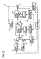
- Fig. 18 depicts an example in which the p-th order synthesis filter 14 is used as also the p'-th order synthesis filter 29a, the parts corresponding to those in Fig. 12 being identified by the same reference numerals.
- the p-th order synthesis filter 14, the n-th order synthesis filter 29b and the switch SW are connected in the same manner as in the Fig. 17 embodiment.
- the input to the excitation signal buffer 42 is the output signal from the switch SW.
- Fig. 19 there is shown, as being applied to the Fig. 8 embodiment, an example in which the p'-th order synthesis filter 29a is used also as the p-th order synthesis filter 14.
- the p'-th order synthesis filter 29a is provided in place of the p-th order synthesis filter 14 in the Fig. 17 embodiment, and as is the case with the Fig. 8 embodiment, the synthesized signal is subjected to an LPC analysis in the LPC analysis part 26, and the resulting p'-th order LP coefficients are set in the p'-th order synthesis filter 29a.
- the LPC analysis part 12, the quantization part 13 and the LP synthesis filter 14 are omitted. In this instance, the code indicative of the LP coefficients ⁇ i are not output.
- the p-th order synthesis filter 14 can be used also as the p'-th order synthesis filter 29a as in the case of Fig. 19.
- Fig. 15 depicts such a modification.
- the p'-th order synthesis filter 29a, the n-th order synthesis filter 29b and the switch SW are connected in the same manner as shown in Fig. 8. It will easily be understood that the LP inverse filter 27 is omitted and that the output signal from the switch SW is provided via the excitation signal buffer 42 to an LPC analysis part 43 as required. In this instance, the LP coefficient code need not be output.
- Fig. 21 depicts in block form the mode decision part 41 which is used when the same synthesis filter is used both as the p-th order synthesis filter 14 and the p'-th order synthesis filter 29a as described above with reference to Figs. 17 to 20.
- the input acoustic signal is subjected to LP inverse filtering by the LP inverse filter 41A having set therein the filter coefficients ⁇ i (or ⁇ ' k ) and internal state of the p-th (or p'-th) order synthesis filter 14 (or 29a) to be used, then the resulting residual signal (corresponding to the estimated input excitation signal to the p'-th order synthesis filter 29a) e 1 is fed to the LP inverse filter 41B.
- the LP inverse filter 4 1 B has set therein the filter coefficients and internal state of the n-th order synthesis filter 29b and performs LP inverse filtering of the residual signal e 1 to produce the residual signal (corresponding to the estimated input excitation signal to the n-th order synthesis filter 29) e 2 , which is compared by the comparator 41C with the residual signal e 1 .
- Fig. 22 is a block diagram illustrating a decoding apparatus corresponding to the coding apparatus shown in Fig. 8, the parts corresponding to those in conventional decoding apparatus of Fig. 2 being identified by the same reference numerals.
- a cascade-connected synthesis filter 59 formed by a cascade connection of a p'-th order LP synthesis filter 59a and an n-th order LP synthesis filter 59b.
- These synthesis filters 33 and 59 are driven by the excitation signal from the adder 37.
- a switch SW3 is controlled, through which the output from either one of the synthesis filters 33 and 59 is provided as a synthesized signal to the post filter 38.
- the input LP coefficient code is decoded in the decoding part 32, and the decoded p-th LP coefficients ⁇ i are used to set the filter coefficients in the p-th order synthesis filter 33.
- a synthesized signal buffer 54, an LPC analysis part 55, an LP inverse filter 56 and an LPC analysis part 57 are identical in operation with the synthesized signal buffer 25, the LPC analysis part 26, the LP inverse filter 27 and the LPC analysis part 28 in the coding apparatus of Fig. 8.
- the synthesized signal via the switch SW3 is stored in the synthesized signal buffer 54, and it is LPC analyzed in the LPC analysis part 55.
- the filter coefficients of the p'-th order synthesis filter 59a are set.
- the p'-th order LP coefficients ⁇ ' k are set in the LP inverse filter 56, to which the synthesized signal is applied to generate a residual signal.
- the residual signal is LPC analyzed in the LPC analysis part 57, and the resulting n-th order LP coefficients ⁇ j are set as filter coefficients in the n-th order synthesis filter 59b.
- This embodiment is identical with the Fig. 2 prior art example, and no further description will be given.
- Fig. 23 depicts in block form another embodiment of the decoding apparatus according to the present invention that corresponds to the coding apparatus of Fig. 12, the parts corresponding to those in Fig. 22 being identified by the same reference numerals.
- the LP inverse filter 56 in Fig. 22 is omitted, but instead the excitation signal from the adder 37 or the output signal from the n-th order synthesis filter 59b is selectively applied via a switch SW4 to an excitation signal buffer 58 for temporary storage therein, then the excitation signal is LPC analyzed in the LPC analysis part 57 to obtain the n-th order LP coefficients ⁇ j , which are set as filter coefficients in the n-th order synthesis filter 59b.
- the switch SW4 is switched in synchronization with the switch SW3.
- the LP coefficients ⁇ ' k and ⁇ j of the LPC analysis parts 26 and 28 also need to be encoded and output.
- the decoding apparatus in such an instance, as depicted in Fig. 24, the p'-th order LP coefficients ⁇ ' k are decoded from the input codes in a decoding part 50a and are set in the p'-th order synthesis filter 59a, then the n-th order LP coefficients ⁇ j are decoded from the input codes in a decoding part 50b and are set in the n-th order synthesis filter 59b.
- the other parts and their operations are the same as in the Fig. 22 embodiment.
- Fig. 25 depicts in block form a decoding apparatus corresponding to the coding apparatus of Fig. 18.
- the outputs of the adder 37 and the n-th order synthesis filter are selectively connected via the switch SW3 to the input of the p-th order synthesis filter 33, the output of which is connected to the input of the post filter 38.
- the synthesized signal from the p-th order synthesis filter 33 is temporarily stored in the synthesized signal buffer 54, thereafter being applied to the LP inverse filter 56.
- the filter coefficients of the LP inverse filter 56 are determined based on the p-th order LP coefficients ⁇ i provided from the decoding part 32.
- the other parts and their operations are the same as in the Fig. 22 embodiment.
- Fig. 26 illustrates in block form a decoding apparatus corresponding to the coding apparatus of Fig. 17.
- the synthesized signal buffer 54, the LP inverse filter 56 and the LPC analysis part 57 in Fig. 25 are omitted, and the code representing the n-ty LP coefficients ⁇ j is decoded in the decoding part 50b and the decoded LP coefficients are set as filter coefficients in the n-th order synthesis filter 59b.
- Fig. 27 depicts in block form a decoding apparatus corresponding to the coding apparatus of Fig. 19.
- the p-th order synthesis filter 33 in Fig. 25 is replaced with the p'-th order synthesis filter 59a and the p'-th order LP coefficients ⁇ ' k obtained by analyzing the synthesized signal in the LPC analysis part 55 are set in the p'-th order synthesis filter 59a.
- the Fig. 27 depicts in block form a decoding apparatus corresponding to the coding apparatus of Fig. 19.
- the p-th order synthesis filter 33 in Fig. 25 is replaced with the p'-th order synthesis filter 59a and the p'-th order LP coefficients ⁇ ' k obtained by analyzing the synthesized signal in the LPC analysis part 55 are set in the p'-th order synthesis filter 59a.
- the synthesized signal from the synthesized signal buffer 54 is inverse filtered by an LP inverse filter 58 to obtain an residual signal, which is analyzed in the LPC analysis part 57, and the resulting n-th order LP coefficients ⁇ j are set in the n-th order synthesis filter 59b.
- Fig. 28 depicts in block form a decoding apparatus corresponding to a modification of the Fig. 19 coding apparatus in which the LP inverse filter 27 is omitted and the excitation signal is applied to the LPC analysis part 28.
- the parts corresponding to those in Fig. 27 are identified by the same reference numerals.
- the LP inverse filter 56 in Fig. 27 is omitted, but instead the excitation signal, which is the output signal from the switch SW3, is provided to the LPC analysis part 57 to obtain the n-th order LP coefficients.
- the p-th order LP coefficients ⁇ i are decoded in the decoding part 32 as indicated by the broken lines, and the p-th order LP coefficients ⁇ i are set in the p-th order synthesis filter 33 in place of the p'-th order synthesis filter 59a.
- the decoding apparatus is also configured accordingly.
- the decoding apparatus of Fig. 25 is modified as depicted in Fig. 29. That is, adaptive codebooks 34A, 34B, fixed codebooks 35A, 35B and gain codebooks 36A, 36B are provided, which are identical with the adaptive codebooks 15A, 15B, the fixed codebooks 21A, 21B and the gain codebooks 17A, 17B in Fig. 16.
- the adaptive codebooks 34A, 34B, the fixed codebooks 35A, 35B and the gain codebooks 36A, 36B are switched by switches SW51, SW53 and SW54 in ganged relation to the switch SW3 so that one of the two codebooks of each pair is selected.
- the other operations are the same as in the Fig. 25 embodiment.
- the selective use of one of the two codebooks of each pair in accordance with the mode code as described above is also applicable to the embodiments depicted in Figs. 22 to 24, 27 and 28.
- the functions of the coding and decoding apparatuses described above can also be implemented by executing computer programs.
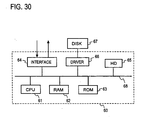
- FIG. 30 illustrates a computer configuration for implementing the coding and decoding methods according to the present invention.
- a computer 60 includes a CPU 61, a RAM 62, a ROM 63, I/O interface 64, a hard disk 65 and a driver 66 interconnected via a bus 68.
- the ROM 63 has written therein a basic program for operating the computer 60, and the hard disk 65 has prestored thereon programs for executing the coding and decoding methods according to the present invention. For example, during coding the CPU 61 loads a coding program from the hard disk 65 into the RAM 62, then encodes the input acoustic signal via the interface 54 under the control of the coding program, and outputs codes via the interface 64.
- the programs for implementing the coding and decoding methods according to the present invention may be programs recorded on an external disk unit 67 connected vi the driver 66 to the internal bus 68.
- the programs for implementing the coding and decoding methods according to the present invention may be recorded on a magnetic recording medium, or such a recording medium as an IC memory or compact disc.
- a synthesized signal is estimated for an input signal, then the synthesized signal is used to estimate the audio coding quality which would be obtained in the case of using a low-order synthesis filter and the audio coding quality which would be obtained in the case of using a cascade-connected synthesis filter formed by a cascade connection of high- and low-order synthesis filters, and audio coding is performed using the synthesis filter which provides higher quality in coding.
- the low-order filter is selected in which are set predictive coefficients obtained from only a low-order linear prediction for expressing the spectral envelope
- the cascade-connected synthesis filter is selected in which are set predictive coefficients obtained by the low-order linear prediction for expressing the spectral envelope and a high-order linear prediction for expressing a fine spectral structure of a residual signal of the low-order linear prediction.
- a low-order synthesis filter and a cascade-connected synthesis filter composed of low- and high-order synthesis filters are provided, and that one of the synthesis filters which fits the synthesized signal to be decoded is selected in accordance with the input mode code--this ensures high quality audio coding.
Landscapes
- Engineering & Computer Science (AREA)
- Physics & Mathematics (AREA)
- Computational Linguistics (AREA)
- Signal Processing (AREA)
- Health & Medical Sciences (AREA)
- Audiology, Speech & Language Pathology (AREA)
- Human Computer Interaction (AREA)
- Acoustics & Sound (AREA)
- Multimedia (AREA)
- Spectroscopy & Molecular Physics (AREA)
- Compression, Expansion, Code Conversion, And Decoders (AREA)
Claims (47)
- Audio-Codierverfahren zum Codieren eines akustischen Eingangssignals durch Erzeugen eines synthetisierten akustischen Signals durch Verwendung eines Codebuchmittels (15, 21), das Erregungsvektoren in Entsprechung zu jeweiligen Indizes enthält, und Absuchen des Codebuchmittels (15, 21) nach Erregungsvektoren, die den Fehler zwischen dem akustischen Eingangssignal und dem synthetisierten akustischen Signal minimieren, wobei das Verfahren die Schritte umfasst:(a) Festlegen, basierend auf dem akustischen Eingangssignal und einem früheren synthetisierten akustischen Signal, von Koeffizienten für ein erstes LP-Synthesefilter (14) p-ter Ordnung und von Koeffizienten für ein reihengeschaltetes Synthesefilter (29), bestehend aus einem zweiten LP-Synthesefilter (29a) p'-ter Ordnung und einem dritten LP-Synthesefilter (29b) n-ter Ordnung, wobei p' gleich oder nahezu gleich p und n größer als p ist;(b) Erhalten, als erste und zweite geschätzte Erregungssignale zum Ansteuern des ersten LP-Synthesefilters (14) beziehungsweise des reihengeschalteten Synthesefilters (29), von ersten und zweiten Restsignalen durch inverses Filtern eines dem akustischen Eingangssignal entsprechenden Signals durch ein erstes inverses Filter (41A), das eine Übertragungsfunktion invers zu derjenigen des ersten LP-Synthesefilters (14) hat, und ein zweites inverses Filter (41 B), das eine Übertragungsfunktion invers zu derjenigen des reihengeschalteten Synthesefilters (29) hat;(c) Festlegen, anhand des ersten und zweiten Restsignals, desjenigen unter dem ersten LP-Synthesefilter (14) und dem reihengeschalteten Synthesefilter (29), das eine höhere Codierqualität für das akustische Eingangssignal liefert, und Auswählen des so festgelegten Synthesefilters als ein Synthesefilter für die Audio-Codierung;(d) Anwenden von Verstärkungen auf aus dem Codebuchmittel (15, 21) ausgewählte Erregungsvektoren, um ein Erregungssignal zu erhalten, Erzeugen eines synthetisierten akustischen Signals durch Anlegen des Erregungssignals an das in Schritt (c) ausgewählte Synthesefilter, und Berechnen des Fehlers zwischen dem akustischen Eingangssignal und dem synthetisierten akustischen Signal;(e) Wiederholen von Schritt (d) für jeden Erregungsvektor in den Codebuchmittel (15, 21), um den Erregungsvektor und die Verstärkung festzulegen, die den Fehler minimieren; und(f) Ausgeben von Codes, die wenigstens den den in Schritt (e) festgelegten Erregungsvektoren entsprechenden Index umfassen, als Codebuchindizes, eines die in Schritt (e) festgelegten Verstärkungen darstellenden Verstärkungsindex und eines Moduscodes, der darstellt, welches unter dem ersten LP-Synthesefilter (14) und dem reihengeschalteten Synthesefilter (29) ausgewählt worden ist.
- Verfahren nach Anspruch 1, bei dem Schritt (a) die Schritte umfasst:(a-1) Durchführen einer LPC-Analyse p-ter Ordnung an einem jeweiligen Rahmen des akustischen Eingangssignals, um erste LP-Koeffizienten zu erhalten, und Setzen von diesen in dem ersten LP-Synthesefilter (14);(a-2) Durchführen einer LPC-Analyse p'-ter Ordnung an einem früheren synthetisierten akustischen Signal, das früheren Rahmen des akustischen Eingangssignals entspricht, die dem jeweiligen Rahmen vorangehen, um zweite LP-Koeffizienten zu erhalten;(a-3) Durchführen von inverser LP-Filterung des früheren synthetisierten akustischen Signals basierend auf den zweiten LP-Koeffizienten, um ein LP-Restsignal zu erhalten;(a-4) Durchführen einer LPC-Analyse n-ter Ordnung an dem LP-Restsignal, um dritte LP-Koeffizienten zu erhalten; und(a-5) Setzen der zweiten LP-Koeffizienten und der dritten LP-Koeffizienten in dem zweiten beziehungsweise dritten LP-Synthesefilter (29a, 29b) des reihengeschalteten Synthesefilters (29);wobei die in Schritt (f) ausgegebenen Codes einen die ersten LP-Koeffizienten darstellenden LP-Koeffizientencode enthalten.
- Verfahren nach Anspruch 1, bei dem Schritt (a) die Schritte umfasst:(a-1) Durchführen einer LPC-Analyse p-ter Ordnung an einem jeweiligen Rahmen des akustischen Eingangssignals, um erste LP-Koeffizienten zu erhalten, und Setzen von diesen in dem ersten LP-Synthesefilter (14);(a-2) Durchführen einer LPC-Analyse p'-ter Ordnung an einem früheren synthetisierten akustischen Signal, das früheren Rahmen des akustischen Eingangssignals entspricht, die dem jeweiligen Rahmen vorangehen, um zweite LP-Koeffizienten zu erhalten;(a-3) Durchführen einer LPC-Analyse n-ter Ordnung an einem den früheren Rahmen entsprechenden früheren Erregungssignal, um dritte LP-Koeffizienten zu erhalten; und(a-4) Setzen der zweiten LP-Koeffizienten und der dritten LP-Koeffizienten in dem zweiten beziehungsweise dritten LP-Synthesefilter (29a, 29b) des reihengeschalteten Synthesefilters (29);wobei die ausgegebenen Codes in Schritt (f) einen die ersten LP-Koeffizienten darstellenden LP-Koeffizientencode enthalten.
- Verfahren nach Anspruch 1, bei dem p = p'; das erste und das zweite LP-Synthesefilter durch gemeinsame Verwendung eines einzigen LP-Synthesefilters (14) p-ter Ordnung als erstes und zweites LP-Synthesefilter implementiert sind; und Schritt (a) die Schritte umfasst:(a-1) Durchführen einer LPC-Analyse p-ter Ordnung an dem akustischen Eingangssignal, um erste LP-Koeffizienten zu erhalten;(a-2) Durchführen von inverser LP-Filterung an dem akustischen Eingangssignal basierend auf den ersten LP-Koeffizienten, um ein LP-Restsignal zu erhalten;(a-3) Durchführen einer LPC-Analyse n-ter Ordnung an dem LP-Restsignal, um dritte LP-Koeffizienten zu erhalten; und(a-4) Setzen der ersten LP-Koeffizienten und der dritten LP-Koeffizienten in dem LP-Synthesefilter (14) p-ter Ordnung beziehungsweise dem dritten LP-Synthesefilter (29b);wobei die ausgegebenen Codes in Schritt (f) LP-Koeffizientencodes enthalten, die die ersten LP-Koeffizienten und die dritten LP-Koeffizienten darstellen.
- Verfahren nach Anspruch 1, bei dem p = p'; das erste und das zweite LP-Synthesefilter durch gemeinsame Verwendung eines einzigen LP-Synthesefilters (14) p-ter Ordnung selektiv als erstes und als zweites LP-Synthesefilter implementiert sind; und Schritt (a) die Schritte umfasst:(a-1) Durchführen einer LPC-Analyse p-ter Ordnung an einem jeweiligen Rahmen des akustischen Eingangssignals, um erste LP-Koeffizienten zu erhalten;(a-2) Durchführen einer LPC-Analyse n-ter Ordnung an einem früheren Erregungssignal, das früheren Rahmen des akustischen Eingangssignal entspricht, die dem jeweiligen Rahmen vorangehen, um dritte LP-Koeffizienten zu erhalten; und(a-3) Setzen der ersten LP-Koeffizienten und der dritten LP-Koeffizienten in dem LP-Synthesefilter (14) p-ter Ordnung beziehungsweise dem dritten Synthesefilter (29b);wobei die ausgegebenen Codes in Schritt (f) einen die ersten LP-Koeffizienten repräsentierenden LP-Koeffizientencode enthalten.
- Verfahren nach Anspruch 1, bei dem p = p'; das erste und das zweite Synthesefilter durch gemeinsame Verwendung eines einzigen LP-Synthesefilters (29a) p-ter Ordnung als das erste und das zweite LP-Synthesefilter implementiert sind; und Schritt (a) die Schritte umfasst:(a-1) Durchführen einer LPC-Analyse p-ter Ordnung an einem früheren synthetisierten akustischen Signal, das früheren Rahmen des akustischen Eingangssignals entspricht, die dem gegenwärtigen Rahmen vorangehen, um erste LP-Koeffizienten zu erhalten;(a-2) Durchführen von inverser LP-Filterung an dem früheren synthetisierten akustischen Signal basierend auf den ersten LP-Koeffizienten, um ein LP-Restsignal zu erhalten;(a-3) Durchführen einer LPC-Analyse n-ter Ordnung an dem LP-Restsignal, um dritte LP-Koeffizienten zu erhalten; und(a-4) Setzen der ersten LP-Koeffizienten und der dritten LP-Koeffizienten in dem LP-Synthesefilter (29a) p-ter Ordnung beziehungsweise dem dritten LP-Synthesefilter (29b).
- Verfahren nach Anspruch 1, bei dem p = p'; das erste und das zweite LP-Synthesefilter durch gemeinsame Verwendung eines einzigen LP-Synthesefilters (29a) p-ter Ordnung als das erste und das zweite LP-Synthesefilter implementiert sind; und Schritt (a) die Schritte umfasst:(a-1) Durchführen einer LPC-Analyse p-ter Ordnung an einem früheren synthetisierten akustischen Signal, das früheren Rahmen des akustischen Eingangssignals, die dem gegenwärtigen Rahmen vorangehen, entspricht, um erste LP-Koeffizienten zu erhalten;(a-2) Durchführen einer LPC-Analyse n-ter Ordnung an einem früheren Erregungssignal, das den früheren Rahmen entspricht, um dritte LP-Koeffizienten zu erhalten; und(a-3) Setzen der ersten LP-Koeffizienten und der dritten LP-Koeffizienten in dem LP-Synthesefilter (29a) p-ter Ordnung beziehungsweise dem dritten LP-Synthesefilter (29b).
- Verfahren nach einem der Ansprüche 2 bis 7, bei dem Schritt (b) die Schritte umfasst:(b-1) Durchführen von inverser LP-Filterung an dem akustischen Eingangssignal basierend auf den ersten LP-Koeffizienten, um das erste Restsignal zu erhalten; und(b-2) Durchführen von inverser. LP-Filterung an dem akustischen Eingangssignal durch Verwendung der Filterkoeffizienten des reihengeschalteten Synthesefilters (29), um das zweite Restsignal zu erhalten;wobei Schritt (c) das Vergleichen der Leistung des ersten Restsignals mit der Leistung des zweiten Restsignals und, wenn die Leistung des ersten Restsignals kleiner als die Leistung des zweiten Restsignals ist, das Auswählen des ersten LP-Synthesefilters (14) und anderenfalls das Auswählen des reihengeschalteten Synthesefilters (29) umfasst.
- Verfahren nach einem der Ansprüche 4 bis 7, bei dem Schritt (b) die Schritte umfasst:(b-1) Durchführen von inverser LP-Filterung an dem akustischen Eingangssignal basierend auf den ersten LP-Koeffizienten, um das erste Restsignal zu erhalten, wenn das erste LP-Synthesefilter (14, 29a) ausgewählt ist; und(b-2) Durchführen von inverser LP-Filterung an dem ersten Restsignal basierend auf den dritten LP-Koeffizienten, um das zweite Restsignal zu erhalten, wenn das reihengeschaltete Synthesefilter (29) ausgewählt ist;wobei Schritt (c) das Vergleichen der Leistung des ersten Restsignals mit der Leistung des zweiten Restsignals und, wenn die Leistung des ersten Restsignals kleiner als die Leistung des zweiten Restsignals ist, das Auswählen des ersten LP-Synthesefilters (14) und anderenfalls das Auswählen des reihengeschalteten Synthesefilters (29) umfasst.
- Verfahren nach einem der Ansprüche 2 bis 7, bei dem Schritt (e) das Durchführen von Wahrnehmungsgewichtung an dem Fehler und das Festlegen der Codebuchindizes und des Verstärkungsindex derart, dass der wahrnehmungsgewichtete Fehler minimiert ist, umfasst, und Schritt (b) die Schritte umfasst:(b-1) Durchführen von Wahrnehmungsgewichtung an dem akustischen Eingangssignal und Durchführung von Wahrnehmungsgewichtung invers zu der auf das akustische Eingangssignal angewandten an dem wahrnehmungsgewichteten akustischen Eingangssignal, um ein geschätztes synthetisiertes akustisches Signal als das dem akustischen Eingangssignal entsprechende Signal zu erhalten;(b-2) Durchführen von inverser LP-Filterung an dem geschätzten synthetisierten akustischen Signal basierend auf den ersten LP-Koeffizienten, um das erste Restsignal zu erhalten; und(b-3) Durchführen von inverser LP-Filterung an dem geschätzten synthetisierten akustischen Signal basierend auf den Filterkoeffizienten des reihengeschalteten Synthesefilters (29), um das zweite Restsignal zu erhalten;wobei Schritt (c) ein Schritt des Vergleichens der Leistung des ersten Restsignals mit der Leistung des zweiten Restsignals und, wenn die Leistung des ersten Restsignals kleiner als die Leistung des zweiten Restsignals ist, des Auswählens des ersten LP-Synthesefilters (14) und anderenfalls des Auswählens des reihengeschalteten Synthesefilters (29) ist.
- Verfahren nach einem der Ansprüche 2 bis 7, bei dem Schritt (e) das Durchführen von Wahrnehmungsgewichtung an dem Fehler und das Festlegen des Codebuchindex und des Verstärkungsindex derart, dass der wahrnehmungsgewichtete Fehler minimiert ist, umfasst, und Schritt (b) die Schritte umfasst:(b-1) Anwenden von Wahrnehmungsgewichtung invers zu der auf den Fehler angewandten auf eine Null-Eingabe, um einen Fehler zu schätzen;(b-2) Subtrahieren des in Schritt (b-1) geschätzten Fehlers von dem akustischen Eingangssignal, um ein geschätztes synthetisiertes akustisches Signal als das dem akustischen Eingangssignal entsprechende Signal zu erhalten;(b-3) Durchführen von inverser LP-Filterung an dem geschätzten synthetisierten akustischen Signal basierend auf den ersten LP-Koeffizienten, um das erste Restsignal zu erhalten; und(b-4) Durchführen von inverser LP-Filterung an dem geschätzten synthetisierten akustischen Signal basierend auf den Filterkoeffizienten des reihengeschalteten Synthesefilters (29), um das zweite Restsignal zu erhalten,wobei Schritt (c) das Vergleichen der Leistung des ersten Restsignals mit der Leistung des zweiten Restsignals und, wenn die Leistung des ersten Restsignals kleiner als die Leistung des zweiten Restsignals ist, das Wählen des ersten LP-Synthesefilters (14) und anderenfalls das Wählen des reihengeschalteten Synthesefilters (29) umfasst.
- Verfahren nach einem der Ansprüche 8 bis 11, bei dem Schritt (c) das Vergleichen einer adaptiv gewichteten Leistung des ersten Restsignals mit einer adaptiv gewichteten Leistung des zweiten Restsignals umfasst.
- Verfahren nach einem der Ansprüche 1 bis 7, bei dem das Codebuchmittel (15, 21) ein unter Verwendung des Synthesefilters p-ter Ordnung vorbereitetes erstes Codebuchmittel (15, 21) und ein unter Verwendung des dritten Synthesefilters (29b) vorbereitetes zweites Codebuchmittel (15, 21) umfasst, wobei das Codebuchmittel (15, 21) zwischen dem ersten und dem zweiten Codebuchmittel (15, 21) umgeschaltet wird, um nach dem Erregungsvektor zu suchen, je nachdem, ob Schritt (c) das erste LP-Synthesefilter (14) oder das reihengeschaltete Synthesefilter (29) wählt.
- Verfahren nach einem der Ansprüche 1 bis 7, bei dem n ≥ 2p.
- Codiervorrichtung zum Codieren eines akustischen Eingangssignals durch Erzeugen eines synthetisierten akustischen Signals durch Verwendung eines Codebuchmittels (15, 21), das Erregungsvektoren in Entsprechung zu jeweiligen Indizes enthält, und durch Absuchen des Codebuchmittels (15, 21) nach Erregungsvektoren, die den Fehler zwischen dem akustischen Eingangssignal und dem synthetisierten akustischen Signal minimieren, wobei die Vorrichtung umfasst:ein Synthesefiltermittel (200), das ein erstes LP-Synthesefilter (14) p-ter Ordnung und ein reihengeschaltetes Synthesefilter (29), gebildet durch eine Reihenschaltung eines zweiten LP-Synthesefilters (29a) p'-ter Ordnung und eines dritten LP-Synthesefilters (29b) n-ter Ordnung, umfasst, wobei ein jeweils unter dem ersten LP-Synthesefilter (14) und dem reihengeschalteten Synthesefilter (29) ausgewähltes Filter durch ein Erregungssignal angesteuert ist, um ein synthetisiertes akustisches Signal zu erzeugen, wobei p' gleich oder nahezu gleich p ist und n höher als p ist;ein Koeffizientenbestimmungsmittel (300) zum Bestimmen, basierend auf dem akustischen Eingangssignal, von LP-Koeffizienten für das erste LP-Synthesefilter (14) und von LP-Koeffizienten für das reihengeschaltete Synthesefilter (29), und zum Setzen der Koeffizienten in dem ersten LP-Synthesefilter (14) beziehungsweise dem reihengeschalteten Synthesefilter (29);ein Modusentscheidungsmittel (41) mit: einem ersten inversen Filter (41A) mit einer Übertragungsfunktion invers zu derjenigen des ersten LP-Synthesefilters (14) zum Durchführen von inverser Filterung an einem dem akustischen Eingangssignal entsprechenden Signal zum Erzeugen eines ersten Restsignals als ein erstes geschätztes Erregungssignal zum Ansteuern des ersten LP-Synthesefilters (14); einem zweiten inversen Filter (41b) mit einer Übertragungsfunktion invers zu derjenigen des reihengeschalteten Synthesefilters (29) zum Durchführen von inverser Filterung an dem dem akustischen Eingangssignal entsprechenden Signal, um ein zweites Restsignal als ein zweites geschätztes Erregungssignal zum Ansteuern des reihengeschalteten Synthesefilters (29) zu erzeugen; und einem Vergleichs-/Entscheidungsmittel (41C) zum Entscheiden, basierend auf dem ersten und zweiten Restsignal, welches unter dem ersten LP-Synthesefilter (14) und dem reihengeschalteten Synthesefilter (29) eine höhere Audio-Codierqualität für das akustische Eingangssignal liefert, wobei das Modusentscheidungsmittel (41) als ein Synthesefilter für die Audio-Codierung dasjenige unter dem ersten LP-Synthesefilter (14) und dem reihengeschalteten Synthesefilter (29) auswählt, von dem entschieden wurde, dass es eine höhere Audio-Codierqualität bietet;ein Verstärkungsanwendungsmittel (17, 22, 23) zum Anwenden einer Verstärkung auf einen aus dem Codebuchmittel (15, 21) ausgewählten Erregungsvektor und zum Anlegen des Erregungsvektors mit darauf angewandter Verstärkung als das Erregungssignal an das ausgewählte unter dem ersten LP-Synthesefilter (14) und dem reihengeschalteten Synthesefilter (29);ein Subtrahiermittel (19) zum Berechnen des Fehlers zwischen dem akustischen Eingangssignal und dem jeweiligen von dem Synthesefiltermittel (200) für jeden Erregungsvektor erzeugten synthetisierten akustischen Signal; undein Steuermittel (16) zum Festlegen des Erregungsvektors und der Verstärkung, die diesen Fehler minimieren, und zum Ausgeben von Codes, die wenigstens den den festgelegten Erregungsvektoren entsprechenden Index umfassen, als Codebuchindizes, eines die festgelegte Verstärkung repräsentierenden Verstärkungsindex und eines Modusindex, der repräsentiert, welches unter dem ersten LP-Synthesefilter (14) und dem reihengeschalteten Synthesefilter (29) von dem Modusentscheidungsmittel (41) ausgewählt worden ist.
- Codiervorrichtung nach Anspruch 15, bei der das Koeffizientenfestlegungsmittel umfasst:ein erstes LPC-Analysemittel (12, 13) zum Durchführen einer LPC-Analyse p-ter Ordnung an einem jeweiligen Rahmen des akustischen Eingangssignals, um erste LP-Koeffizienten zu erhalten, und zum Setzen von diesen in dem ersten LP-Synthesefilter (14);einen Signalpuffer (25) zum jeweiligen Speichern eines früheren synthetisierten akustischen Signals, das Rahmen des akustischen Eingangssignals entspricht, die dem besagten jeweiligen Rahmen vorangehen;ein zweites LPC-Analysemittel (26) zum Durchführen einer LPC-Analyse p'-ter Ordnung an dem in dem Signalpuffer (25) gespeicherten früheren synthetisierten akustischen Signal, um zweite LP-Koeffizienten zu erhalten, und zum Setzen von diesen in dem zweiten LP-Synthesefilter (29a);ein inverses LP-Filter (27), in dem Filterkoeffizienten basierend auf den zweiten LP-Koeffizienten zum Durchführen von inverser LP-Filterung an dem früheren synthetisierten akustischen Signal gesetzt sind, zum Erhalten eines LP-Restsignals; undein drittes LPC-Analysemittel (28) zum Durchführen einer LPC-Analyse n-ter Ordnung an dem LP-Restsignal, um dritte LP-Koeffizienten zu erhalten, und zum Setzen von diesen in dem dritten LP-Synthesefilter (29b);wobei die von dem Steuermittel ausgegebenen Codes einen LP-Koeffizientencode enthalten, der die ersten LP-Koeffizienten repräsentiert.
- Codiervorrichtung nach Anspruch 15, bei der das Koeffizientenfestlegungsmittel umfasst:ein erstes LPC-Analysemittel (12, 13) zum Durchführen einer LPC-Analyse p-ter Ordnung an einem jeweiligen Rahmen des akustischen Eingangssignals, um erste LP-Koeffizienten zu erhalten, und zum Setzen von diesen in dem ersten LP-Synthesefilter (14);einen ersten Signalpuffer (25) zum jeweiligen Speichern eines früheren synthetisierten akustischen Signals, das früheren Rahmen des akustischen Eingangssignals entspricht, die dem besagten jeweiligen Rahmen vorangehen;ein zweites LPC-Analysemittel (26) zum Durchführen einer LPC-Analyse p'-ter Ordnung an dem in dem ersten Signalpuffer gespeicherten früheren synthetisierten akustischen Signal, um zweite LP-Koeffizienten zu erhalten, und zum Setzen von diesen in dem zweiten LP-Synthesefilter (29a);einen zweiten Signalpuffer (42) zum jeweiligen Speichern eines früheren Erregungssignals entsprechend den früheren Rahmen; undein drittes LPC-Analysemittel (43) zum Durchführen einer LPC-Analyse n-ter Ordnung an dem früheren Erregungssignal in dem zweiten Signalpuffer (42), um dritte LP-Koeffizienten zu erhalten, und zum Setzen von diesen in dem dritten LP-Synthesefilter (29b);wobei die von dem Steuermittel (16) ausgegebenen Codes einen die ersten LP-Koeffizienten repräsentierenden LP-Koeffizientencode enthalten.
- Codiervorrichtung nach Anspruch 15, bei der p = p' und das erste und das zweite LP-Synthesefilter (14, 29a) durch gemeinsame Verwendung eines einzigen LP-Synthesefilter (14) p-ter Ordnung selektiv als das erste und das zweite LP-Synthesefilter implementiert sind, wobei:das Synthesefiltermittel (200) ein Schaltmittel (SW) zum Verbinden des Eingangs des dritten LP-Synthesefilters (29b) mit dem Eingang des LP-Synthesefilters (14) p-ter Ordnung zur Umgehung des dritten LP-Synthesefilters (29b), um so das LP-Synthesefilter (14) p-ter Ordnung als das erste LP-Synthesefilter zu wählen, oder zum Verbinden des Ausgangs des dritten LP-Synthesefilters (29b) mit dem Eingang des LP-Synthesefilters (14) p-ter Ordnung, um so das reihengeschaltete Synthesefilter (29) zu wählen, umfasst; unddas Koeffizientenfestlegungsmittel (300) umfasst:wobei die Ausgabecodes des Steuermittels (16) LP-Koeffizientencodes enthalten, die die ersten LP-Koeffizienten und die dritten LP-Koeffizienten repräsentieren.ein erstes LPC-Analysemittel (12, 13) zum Durchführen einer LPC-Analyse p-ter Ordnung an dem akustischen Eingangssignal, um erste LP-Koeffizienten zu erhalten, und zum Setzen von diesen in dem LP-Synthesefilter p-ter Ordnung;ein inverses LP-Filter (27), in dem Filterkoeffizienten basierend auf den ersten LP-Koeffizienten gesetzt sind, um eine inverse LP-Filterung an dem akustischen Eingangssignal vorzunehmen, um ein LP-Restsignal zu erhalten; undein zweites LPC-Analysemittel (28, 45) zum Durchführen einer LPC-Analyse n-ter Ordnung an dem LP-Restsignal, um dritte LP-Koeffizienten zu erhalten, und zum Setzen von diesen in dem dritten LP-Synthesefilter (29b);
- Codiervorrichtung nach Anspruch 15, bei der p = p' und das erste und das zweite LP-Synthesefilter durch gemeinsame Verwendung eines einzigen LP-Synthesefilters p-ter Ordnung selektiv als das erste und das zweite LP-Synthesefilter implementiert sind, wobei:das Synthesefiltermittel (200) Schaltmittel (SW) zum Verbinden des Eingangs des dritten LP-Synthesefilters (29b) mit dem Eingang des LP-Synthesefilters (14) p-ter Ordnung, um damit das dritte LP-Synthesefilter (29) zu umgehen und dadurch das LP-Synthesefilter (14) p-ter Ordnung als das erste LP-Synthesefilter zu wählen, oder zum Verbinden des Ausgangs des dritten LP-Synthesefilters (29b) mit dem Eingang des LP-Synthesefilters (14) p-ter Ordnung, um dadurch das reihengeschaltete Synthesefilter (29) zu wählen, umfasst; unddas Koeffizientenfestlegungsmittel (300) umfasst:wobei die Ausgabecodes des Steuermittels (16) einen LP-Koeffizientencode enthalten, der die ersten LP-Koeffizienten repräsentiert.ein erstes LP-Analysemittel (12, 13) zum Durchführen einer LPC-Analyse p-ter Ordnung an einem jeweiligen Rahmen des akustischen Eingangssignals, um erste LP-Koeffizienten zu erhalten, und zum Setzen von diesen in dem LP-Synthesefilter (14) p-ter Ordnung; undein zweites LPC-Analysemittel (43) zum Durchführen einer LPC-Analyse n-ter Ordnung an einem früheren Erregungssignal des Synthesefilters p-ter Ordnung, das früheren Rahmen des akustischen Eingangssignals entspricht, die dem jeweiligen Rahmen vorangehen, um dritte LP-Koeffizienten zu erhalten, und zum Setzen von diesen in dem dritten LP-Synthesefilter (29b);
- Codiervorrichtung nach Anspruch 15 bei der p = p' und das erste und das zweite LP-Synthesefilter durch gemeinsame Verwendung eines einzigen LP-Synthesefilters p-ter Ordnung selektiv als das erste und das zweite LP-Synthesefilter implementiert sind, wobei:das Synthesefiltermittel (200) ein Schaltmittel (SW) zum Verbinden des Eingangs des dritten LP-Synthesefilters (29b) mit dem Eingang des Synthesefilters (29a) p-ter Ordnung, um damit das dritte LP-Synthesefilter (29) zu umgehen und dadurch das LP-Synthesefilter (29a) p-ter Ordnung als das erste LP-Synthesefilter zu wählen, oder zum Verbinden des Ausgangs des dritten LP-Synthesefilters (29b) mit dem Eingang des LP-Synthesefilters (29a) p-ter Ordnung, um dadurch das reihengeschaltete Synthesefilter (29) zu wählen, umfasst; und wobeidas Koeffizientenfestlegungsmittel (300) umfasst:ein erstes LPC-Analysemittel (26) zum Durchführen einer LPC-Analyse p-ter Ordnung an einem früheren synthetisierten akustischen Signal des, LP-Synthesefilters (29a) p-ter Ordnung, das früheren Rahmen des akustischen Eingangssignals, die dem gegenwärtigen Rahmen vorangehen, entspricht, um erste Koeffizienten zu erhalten, und zum Setzen von diesen in dem LP-Synthesefilter (29a) p-ter Ordnung;ein inverses LP-Filter (27), in dem die ersten LP-Koeffizienten gesetzt sind, zum Durchführen einer inversen Filterung an dem früheren synthetisierten akustischen Signal, um ein LP-Restsignal zu erhalten; undein zweites LPC-Analysemittel (28) zum Durchführen einer LPC-Analyse n-ter Ordnung an dem LP-Restsignal, um dritte LP-Koeffizienten zu erhalten, und zum Setzen von diesen in dem dritten LP-Synthesefilter (29b).
- Codiervorrichtung nach Anspruch 15, bei der p = p' und das erste und das zweite LP-Synthesefilter durch gemeinsame Verwendung eines einzigen LP-Synthesefilters p-ter Ordnung selektiv als das erste und das zweite LP-Synthesefilter implementiert sind, wobei:das Synthesefiltermittel (200) ein Schaltmittel (SW) zum Verbinden des Eingangs des dritten LP-Synthesefilters (29b) mit dem Eingang des Synthesefilters (29a) p-ter Ordnung, um damit das dritte LP-Synthesefilter (29) zu umgehen und dadurch das LP-Synthesefilter (29a) p-ter Ordnung als das erste LP-Synthesefilter zu wählen, oder zum Verbinden des Ausgangs des dritten LP-Synthesefilters (29b) mit dem Eingang des LP-Synthesefilters (29a) p-ter Ordnung, um dadurch das reihengeschaltete Synthesefilter (29) zu wählen, umfasst; und wobeidas Koeffizientenfestlegungsmittel (300) umfasst:ein erstes LPC-Analysemittel (26) zum Durchführen einer LPC-Analyse p-ter Ordnung an einem früheren synthetisierten akustischen Signal des LP-Synthesefilters (29a) p-ter Ordnung, das früheren Rahmen des akustischen Eingangssignals, die dem gegenwärtigen Rahmen vorangehen, entspricht, um erste Koeffizienten zu erhalten, und zum Setzen von diesen in dem LP-Synthesefilter (29a) p-ter Ordnung; undein zweites LPC-Analysemittel (43) zum Durchführen einer LPC-Analyse n-ter Ordnung an einem früheren Erregungssignal des LP-Synthesefilters (29a) p-ter Ordnung, das früheren Rahmen entspricht, um dritte LP-Koeffizienten zu erhalten, und zum Setzen von diesen in dem dritten LP-Synthesefilter (29).
- Codiervorrichtung nach einem der Ansprüche 16 bis 21, bei dem:in dem ersten inversen Filter (41A) die ersten LP-Koeffizienten gesetzt sind und das erste inverse Filter inverse LP-Filterung an dem akustischen Eingangssignal durchführt, um das erste Restsignal zu erzeugen;in dem zweiten inversen Filter (41 B) die Filterkoeffizienten des reihengeschalteten Synthesefilters (29) gesetzt sind und das zweite inverse Filter inverse LP-Filterung an dem akustischen Eingangssignal durchführt, um das zweite Restsignal zu erzeugen; unddas Vergleichs-/Entscheidungsmittel (41 C) die Leistung des ersten LP-Restsignals mit der Leistung des zweiten Restsignals vergleicht und das Schaltmittel (SW) steuert, um das erste LP-Synthesefilter (14) auszuwählen, wenn die Leistung des ersten Restsignals kleiner als die Leistung des zweiten Restsignals ist, und das reihengeschaltete Synthesefilter (29) auszuwählen, wenn die Leistung des zweiten Restsignals kleiner als die Leistung des ersten Restsignals ist.
- Codiervorrichtung nach einem der Ansprüche 18 bis 21, bei dem:in dem ersten inversen Filter (41A) die ersten LP-Koeffizienten gesetzt sind und das erste inverse Filter inverse LP-Filterung an dem akustischen Eingangssignal durchführt, um das erste Restsignal zu erzeugen, wenn das erste LP-Synthesefilter (14, 29a) ausgewählt ist;in dem zweiten inversen Filter (41 B) die dritten LP-Koeffizienten gesetzt sind und das zweite inverse Filter inverse LP-Filterung an dem ersten Restsignal durchführt, um das zweite Restsignal zu erzeugen, wenn das reihengeschaltete Synthesefilter (29) ausgewählt ist; unddas Vergleichs-/Entscheidungsmittel (41 C) die Leistung des ersten Restsignals mit der Leistung des zweiten Restsignals vergleicht und das Schaltmittel (SW) steuert, um das erste LP-Synthesefilter (14, 29a) auszuwählen, wenn die Leistung des ersten geschätzten Erregungssignals kleiner als die Leistung des zweiten geschätzten Erregungssignals ist und das reihengeschaltete Synthesefilter (29) auszuwählen, wenn die Leistung des zweiten geschätzten Signals kleiner als die Leistung des ersten geschätzten Signals ist.
- Codiervorrichtung nach einem der Ansprüche 15 bis 21, ferner mit einem ersten Gewichtungsfilter (20) zum Wahrnehmungsgewichten des Fehlers, um einen wahrnehmungsgewichteten Fehler zu erzeugen, wobei:das Modusentscheidungsmittel (41) ein zweites Wahrnehmungsgewichtungsfilter (41 D) zum Wahrnehmungsgewichten des akustischen Eingangssignals, um ein geschätztes wahrnehmungsgewichtetes synthetisiertes akustisches Signal zu erzeugen, und ein inverses Wahrnehmungsgewichtungsfilter (41 E) zum Vornehmen einer Gewichtung invers zu derjenigen des zweiten Wahrnehmungsgewichtungsfilters (41 D) an dem geschätzten wahrnehmungsgewichteten synthetisierten akustischen Signal, um das geschätzte synthetisierte akustische Signal zu erzeugen, enthält;in dem ersten inversen Filter (41A) erste LP-Koeffizienten gesetzt sind und das erste inverse Filter inverse LP-Filterung des geschätzten synthetisierten akustischen Signals durchführt, um das erste Restsignal zu erzeugen;in dem zweiten inversen Filter (41 B) die Koeffizienten des reihengeschalteten Synthesefilters gesetzt sind und das zweite inverse Filter inverse LP-Filterung an dem geschätzten synthetisierten akustischen Signal durchführt, um das zweite Restsignal zu erzeugen; unddas Vergleichs-/Entscheidungsmittel (41 C) die Leistung des ersten Restsignals mit der Leistung des zweiten Restsignals vergleicht und das Schaltmittel (SW) steuert, um das erste LP-Synthesefilter (14, 29a) zu wählen, wenn die Leistung des ersten Restsignals kleiner als die Leistung des zweiten Restsignals ist, und das reihengeschaltete Synthesefilter (29) zu wählen, wenn die Leistung des zweiten Restsignals kleiner als die Leistung des ersten Restsignals ist.
- Codiervorrichtung nach einem der Ansprüche 15 bis 21, ferner mit:einem Wahrnehmungsgewichtungsfilter (20) zum Wahrnehmungsgewichten des Fehlers, um einen wahrnehmungsgewichteten Fehler zu erzeugen, wobei:das Modusentscheidungsmittel (41) ein inverses Wahrnehmungsgewichtungsfilter (41 E) zum Vornehmen einer Gewichtung invers zu derjenigen des Wahrnehmungsgewichtungsfilters an einer Null-Eingabe zum Schätzen eines Fehlers und ein Subtrahiermittel (41 H) zum Subtrahieren des geschätzten Fehlers von dem akustischen Eingangssignal zum Erzeugen eines geschätzten synthetisierten akustischen Signals als das dem akustischen Eingangssignal entsprechende Signal enthält;in dem ersten inversen Filter (41A) die ersten LP-Koeffizienten gesetzt sind und das erste inverse Filter eine inverse LP-Filterung an dem geschätzten synthetisierten akustischen Signal durchführt, um das erste Restsignal zu erzeugen;in dem zweiten inversen Filter (41 B) die Koeffizienten des reihengeschalteten Synthesefilters gesetzt sind und das zweite inverse Filter inverse LP-Filterung an dem geschätzten synthetisierten akustischen Signal durchführt, um das zweite Restsignal zu erzeugen; unddas Vergleichs-/Entscheidungsmittel (41 C) die Leistung des ersten Restsignals mit der Leistung des zweiten Restsignals vergleicht und das Schaltmittel (SW) steuert, um das erste LP-Synthesefilter (14, 29a) auszuwählen, wenn die Leistung des ersten Restsignals kleiner als die Leistung des zweiten Restsignals ist, und das reihengeschaltete Synthesefilter (29) auszuwählen, wenn die Leistung des zweiten Restsignals kleiner als die Leistung des ersten Restsignals ist.
- Codiervorrichtung nach einem der Ansprüche 15 bis 21, bei der das Codebuchmittel (15, 21) und das Verstärkungsanwendungsmittel (17, 22, 23) jeweils ein erstes Erregungsvektorcodebuch (15A, 21A) und ein erstes Verstärkungscodebuch (17A), die unter Verwendung des Synthesefilters (14, 29a) p-ter Ordnung vorbereitet sind, und ein zweites Erregungsvektorcodebuch (15B, 21 B) und ein zweites Verstärkungscodebuch (17B), die unter Verwendung des dritten LP-Synthesefilters (29b) vorbereitet sind, umfasst, wobei das Codebuchmittel (15, 21) zwischen dem ersten und zweiten Erregungsvektorcodebuch und zwischen dem ersten und zweiten Verstärkungscodebuch umgeschaltet wird, um nach dem Erregungsvektor zu suchen, je nachdem, ob das Modusentscheidungsmittel (41) das erste LP-Synthesefilter (14) oder das reihengeschaltete Synthesefilter (29) wählt.
- Audio-Decodierverfahren zum Decodieren von Eingangscodes, die wenigstens einen Codebuchindex, einen Verstärkungsindex und einen Moduscode enthalten, wobei das Verfahren die Schritte umfasst:(a) Wählen eines dem Codebuchindex entsprechenden Erregungsvektors aus einem Erregungsvektorcodebuch;(b) Wählen einer dem Verstärkungsindex entsprechenden Verstärkung aus einem Verstärkungscodebuch und Anwenden der Verstärkung auf den Erregungsvektor, um ein Erregungssignal zu erzeugen;(c) Erzeugen von ersten LP-Koeffizienten, zweiten LP-Koeffizienten und dritten LP-Koeffizienten aus wenigstens einem der Eingangscodes und einem früheren synthetisierten akustischen Signal, das aus dem gegenwärtigen Rahmen der Eingangscodes vorangehenden früheren Rahmen synthetisiert ist, und Setzen der LP-Koeffizienten in einem ersten LP-Synthesefilter (33) p-ter Ordnung, einem zweiten LP-Synthesefilter (59a) p'-ter Ordnung beziehungsweise einem dritten LP-Synthesefilter (59b) n-ter Ordnung, wobei das zweite und das dritte LP-Synthesefilter (59a, 59b) in Reihe geschaltet sind, um ein reihengeschaltetes Synthesefilter (59) zu bilden, wobei p gleich oder nahezu gleich p' ist und n höher als p ist;(d) Auswählen entweder des ersten LP-Synthesefilters (33) oder des reihengeschalteten Synthesefilters (59) entsprechend dem Moduscode; und(e) Ansteuern des jeweils ausgewählten unter dem ersten LP-Synthesefilter (33) und dem reihengeschalteten Synthesefilter (59) mit dem Erregungssignal, um ein synthetisiertes akustisches Signal zu erzeugen.
- Verfahren nach Anspruch 27, bei dem die Eingangscodes einen LP-Koeffizientencode enthalten, der die ersten LP-Koeffizienten repräsentiert und Schritt (c) die Schritte umfasst:(c-1) Decodieren des LP-Koeffizientencodes zu den ersten LP-Koeffizienten und Setzen von diesen in dem ersten LP-Synthesefilter (33);(c-2) Durchführen einer LPC-Analyse an dem früheren synthetisierten akustischen Signal, um die zweiten LP-Koeffizienten zu erhalten, und Setzen von diesen in dem zweiten LP-Synthesefilter (59a);(c-3) Durchführen von inverser Filterung an dem früheren synthetisierten akustischen Signal durch ein inverses LP-Filter, in dem die zweiten LP-Koeffizienten gesetzt sind, um ein LP-Restsignal zu erhalten; und(c-4) Durchführen einer LPC-Analyse n-ter Ordnung an dem LP-Restsignal, um die dritten LP-Koeffizienten zu erhalten, und Setzen von diesen in dem dritten LP-Synthesefilter (59b).
- Verfahren nach Anspruch 27, bei dem die eingegebenen Codes einen die ersten LP-Koeffizienten repräsentierenden LP-Koeffizientencode enthalten und Schritt (c) die Schritte umfasst:(c-1) Decodieren des LP-Koeffizientencodes zu den ersten LP-Koeffizienten und Setzen von diesen in dem ersten LP-Synthesefilter (33);(c-2) Durchführen einer LPC-Analyse an dem jeweils in einem ersten Signalpuffer gespeicherten früheren synthetisierten akustischen Signal, um zweite LP-Koeffizienten zu erhalten, und Setzen von diesen in dem zweiten LP-Synthesefilter (59a);(c-3) Durchführen einer LPC-Analyse n-ter Ordnung an einem den früheren Rahmen entsprechenden, jeweils in einem zweiten Signalpuffer gespeicherten früheren Erregungssignal, um die dritten LP-Koeffizienten zu erhalten, und Setzen von diesen in dem dritten LP-Synthesefilter (59); und(c-4) Auswählen des Erregungssignals oder des Ausgabesignals aus dem dritten LP-Synthesefilter entsprechend dem Moduscode und Speichern desselben als das frühere Erregungssignal in dem zweiten Signalpuffer.
- Verfahren nach Anspruch 27, bei dem die eingegebenen Codes LP-Koeffizientencodes enthalten, die die ersten, zweiten und dritten LP-Koeffizienten repräsentieren, und Schritt (c) die Schritte umfasst:(c-1) Decodieren der LP-Koeffizientencodes zu den ersten LP-Koeffizienten und Setzen von diesen in dem ersten LP-Synthesefilter (3); und(c-2) Decodieren der LP-Koeffizientencodes zu den zweiten und dritten LP-Koeffizienten und Setzen von diesen in dem zweiten beziehungsweise dritten LP-Synthesefilter (29a, 29b) des reihengeschalteten Synthesefilters (59).
- Verfahren nach Anspruch 27, bei dem p' = p; das erste LP-Synthesefilter und das zweite LP-Synthesefilter durch gemeinsame Verwendung eines einzigen LP-Synthesefilters (33) p-ter Ordnung selektiv als das erste und das zweite LP-Synthesefilter implementiert sind, die eingegebenen Codes einen die ersten LP-Koeffizienten repräsentierenden LP-Koeffizientencode enthalten, und Schritt (c) die Schritte umfasst:(c-1) Decodieren des LP-Koeffizientencodes zu den ersten LP-Koeffizienten und Setzen von diesen in dem LP-Synthesefilter (33) p-ter Ordnung;(c-2) Durchführen von inverser LP-Filterung an dem früheren synthetisierten akustischen Signal durch Verwendung der ersten LP-Koeffizienten, um ein LP-Restsignal zu erzeugen; und(c-3) Durchführen einer LPC-Analyse n-ter Ordnung an dem LP-Restsignal, um die dritten LP-Koeffizienten zu erhalten, und Setzen von diesen in dem dritten LP-Synthesefilter (59b).
- Verfahren nach Anspruch 27, bei dem p' = p; das erste LP-Synthesefilter und das zweite LP-Synthesefilter durch gemeinsame Verwendung eines einzigen LP-Synthesefilters (33; 59a) p-ter Ordnung selektiv als das erste und das zweite LP-Synthesefilter implementiert sind, die eingegebenen Codes einen die ersten LP-Koeffizienten repräsentierenden LP-Koeffizientencode enthalten, und Schritt (c) die Schritte umfasst:(c-1) Decodieren des LP-Koeffizientencodes zu den ersten LP-Koeffizienten und Setzen von diesen in dem LP-Synthesefilter (33; 59a) p-ter Ordnung;(c-2) Durchführen einer LPC-Analyse n-ter Ordnung an dem Eingangssignal des LP-Synthesefilters p-ter Ordnung, um die dritten LP-Koeffizienten zu erhalten, und Setzen von diesen in dem dritten LP-Synthesefilter (59b).
- Verfahren nach Anspruch 27, bei dem p' = p; das erste LP-Synthesefilter und das zweite LP-Synthesefilter durch gemeinsame Verwendung eines einzigen LP-Synthesefilters (59a) p-ter Ordnung selektiv als das erste und das zweite LP-Synthesefilter implementiert sind, und Schritt (c) die Schritte umfasst:(c-1) Durchführen einer LPC-Analyse p-ter Ordnung an dem früheren synthetisierten akustischen Signal, um die ersten LP-Koeffizienten zu erhalten, und Setzen von diesen in dem LP-Synthesefilter (59a) p-ter Ordnung;(c-2) Durchführen von inverser LP-Filterung an dem früheren synthetisierten akustischen Signal durch Verwendung der ersten LP-Koeffizienten, um ein LP-Restsignal zu erzeugen; und(c-3) Durchführen einer LPC-Analyse n-ter Ordnung an dem LP-Restsignal, um die dritten LP-Koeffizienten zu erhalten, und Setzen von diesen in dem dritten LP-Synthesefilter (59b).
- Verfahren nach Anspruch 27, bei dem p' = p; das erste LP-Synthesefilter und das zweite LP-Synthesefilter durch gemeinsame Verwendung eines einzigen LP-Synthesefilters (33; 59a) p-ter Ordnung selektiv als das erste und das zweite LP-Synthesefilter implementiert sind, und Schritt (c) die Schritte umfasst:(c-1) Durchführen einer LPC-Analyse p-ter Ordnung an dem früheren synthetisierten akustischen Signal, um die ersten LP-Koeffizienten zu erhalten, und Setzen von diesen in dem LP-Synthesefilter (33, 59a) p-ter Ordnung; und(c-2) Durchführen einer LPC-Analyse n-ter Ordnung an dem in das Synthesefilter p-ter Ordnung eingegebenen Signal, um die dritten LP-Koeffizienten zu erhalten, und Setzen von diesen in dem dritten LP-Synthesefilter (59b).
- Verfahren nach Anspruch 27, p' = p; das erste LP-Synthesefilter und das zweite LP-Synthesefilter durch gemeinsame Verwendung eines einzigen LP-Synthesefilters (33) p-ter Ordnung selektiv als das erste und das zweite LP-Synthesefilter implementiert sind, die eingegebenen Codes einen die ersten und die zweiten LP-Koeffizienten repräsentierenden LP-Koeffizientencode enthalten, und Schritt (c) die Schritte umfasst:(c-1) Decodieren der LP-Koeffizientencodes zu den ersten LP-Koeffizienten und Setzen von diesen in dem LP-Synthesefilter (33) p-ter Ordnung; und(c-2) Decodieren der LP-Koeffizientencodes zu den dritten LP-Koeffizienten und Setzen von diesen in dem dritten LP-Synthesefilter (59b).
- Verfahren nach einem der Ansprüche 27 bis 35, bei dem das Erregungsvektorcodebuch und das Verstärkungscodebuch jeweils ein erstes Erregungsvektorcodebuch (34a, 35a) und ein erstes Verstärkungscodebuch (36a), das unter Verwendung des ersten LP-Synthesefilters (33) vorbereitet ist, und ein zweites Erregungsvektorcodebuch (34b, 35b) und ein zweites Verstärkungscodebuch (36b), das unter Verwendung des reihengeschalteten Synthesefilters (59) vorbereitet ist, umfassen, und das das erste und das zweite Erregungsvektorcodebuch und das erste und das zweite Verstärkungscodebuch selektiv entsprechend dem Moduscode verwendet werden.
- Audio-Decodiervorrichtung zum Decodieren von Eingangscodes, die wenigstens einen Codebuchindex, einen Verstärkungsindex und einen Moduscode enthalten, wobei die Vorrichtung umfasst:ein Erregungsvektorcodebuch (34, 35), das Erregungsvektoren speichert und eingerichtet ist, einen ausgewählten Erregungsvektor auszugeben, der dem Codebuchindex entspricht;ein Verstärkungsanwendungsmittel (36, 52, 53) zum Anwenden einer aus einem Verstärkungscodebuch (36) entsprechend dem Verstärkungsindex ausgewählten Verstärkung auf den ausgewählten Erregungsvektor, um ein Erregungssignal zu erzeugen;ein Synthesefiltermittel, das aus einem ersten LP-Synthesefilter (33) p-ter Ordnung und einem reihengeschalteten Synthesefilter (59), das durch eine Reihenschaltung eines zweiten und eines dritten LP-Synthesefilters (59a, 59b) p-ter beziehungsweise n-ter Ordnung gebildet ist, besteht, wobei das erste LP-Synthesefilter (33) oder das reihengeschaltete Synthesefilter (59) entsprechend dem Moduscode ausgewählt werden und durch das Erregungssignal angesteuert werden, um ein synthetisiertes akustisches Signal zu erzeugen, wobei p gleich oder nahezu gleich p' und n höher als p ist;einem Koeffizientensetzmittel (320) zum Erzeugen von ersten LP-Koeffizienten, zweiten LP-Koeffizienten und dritten LP-Koeffizienten aus den eingegebenen Codes und/oder einem früheren synthetisierten akustischen Signal, das aus dem gegenwärtigen Rahmen der eingegebenen Codes vorangehenden früheren Rahmen synthetisiert ist, und zum Setzen von diesen in dem ersten LP-Synthesefilter (33), dem zweiten LP-Synthesefilter (59a) beziehungsweise dem dritten LP-Synthesefilter (59b); undein Modusumschaltmittel (51, SW3) zum Auswählen eines Filters unter dem ersten LP-Synthesefilter (33) und dem reihengeschalteten Synthesefilter (59) entsprechend dem Moduscode.
- Decodiervorrichtung nach Anspruch 37, bei der die eingegebenen Codes einen LP-Koeffizientencode, der die ersten LP-Koeffizienten repräsentiert, enthält, und das Koeffizientensetzmittel umfasst:ein Koeffizientendecodiermittel (32) zum Decodieren des LP-Koeffizientencodes zu den ersten LP-Koeffizienten und Setzen von diesen in dem ersten LP-Synthesefilter (33);ein erstes LPC-Analysemittel (54, 55) zum Durchführen einer LPC-Analyse p'-ter Ordnung an dem früheren synthetisierten akustischen Signal, um die zweiten LP-Koeffizienten zu erhalten, und zum Setzen von diesen in dem zweiten LP-Synthesefilter (59a);ein inverses LP-Filter (46) zum Durchführen von inverser Filterung an dem früheren synthetisierten akustischen Signal durch Verwendung der zweiten LP-Koeffizienten, um ein LP-Restsignal zu erhalten; undein zweites LPC-Analysemittel (57) zum Durchführen einer LPC-Analyse n-ter Ordnung an dem LP-Restsignal, um die dritten LP-Koeffizienten zu erhalten, und zum Setzen von diesen in dem dritten LP-Synthesefilter (59b).
- Decodiervorrichtung nach Anspruch 37, bei der die eingegebenen Codes einen LP-Koeffizientencode enthalten, der die ersten LP-Koeffizienten repräsentiert, und das Koeffizientensetzmittel umfasst:ein Koeffizientendecodiermittel (32) zum Decodieren des LP-Koeffizientencodes zu den ersten LP-Koeffizienten und zum Setzen von diesen in dem ersten LP-Synthesefilter (33);ein erstes LPC-Analysemittel (54, 55) zum Durchführen einer LPC-Analyse p'-ter Ordnung an dem früheren synthetisierten akustischen Signal, um die zweiten LP-Koeffizienten zu erhalten, und zum Setzen von diesen in dem zweiten LP-Synthesefilter (59a); undein zweites LPC-Analysemittel (57, 58) zum Durchführen einer LPC-Analyse n-ter Ordnung an dem Erregungssignal, um die dritten LP-Koeffizienten zu erhalten, und zum Setzen von diesen in dem dritten LP-Synthesefilter (59b).
- Decodiervorrichtung nach Anspruch 37, bei der die eingegebenen Codes LP-Koeffizientencodes enthalten, die die ersten, zweiten und dritten LP-Koeffizienten repräsentieren, und das Koeffizientensetzmittel Koeffizientendecodiermittel (32, 50a, 50b) zum Decodieren der LP-Koeffizientencodes zu den ersten LP-Koeffizienten, den zweiten LP-Koeffizienten und den dritten LP-Koeffizienten und zum Setzen von diesen in dem ersten LP-Synthesefilter (33), dem zweiten LP-Synthesefilter (59a) beziehungsweise dem dritten LP-Synthesefilter (59b) umfasst.
- Decodiervorrichtung nach Anspruch 37, bei der p' = p; das erste LP-Synthesefilter und das zweite LP-Synthesefilter durch gemeinsame Verwendung eines einzigen LP-Synthesefilters (33) p-ter Ordnung selektiv als das erste und das zweite LP-Synthesefilter implementiert sind; die eingegebenen Codes einen LP-Koeffizientencode enthalten, der die ersten LP-Koeffizienten repräsentiert; und das Koeffizientensetzmittel umfasst:ein Koeffizientendecodiermittel (32) zum Decodieren des LP-Koeffizientencodes zu den ersten LP-Koeffizienten und zum Setzen von diesen in dem LP-Synthesefilter (33) p-ter Ordnung;ein inverses Filtermittel (54, 56) zum Durchführen von inverser LP-Filterung an dem früheren synthetisierten akustischen Signal durch Verwendung der ersten LP-Koeffizienten, um ein LP-Restsignal zu erzeugen; undein LPC-Analysemittel (57) zum Durchführen einer LPC-Analyse n-ter Ordnung an dem LP-Restsignal, um die dritten LP-Koeffizienten zu erhalten, und zum Setzen von diesen in dem dritten LP-Synthesefilter (59b).
- Decodiervorrichtung nach Anspruch 37, bei der p' = p; das erste LP-Synthesefilter und das zweite LP-Synthesefilter durch gemeinsame Verwendung eines einzigen LP-Synthesefilters (33, 59a) p-ter Ordnung selektiv als das erste und das zweite LP-Synthesefilter implementiert sind; die eingegebenen Codes einen LP-Koeffizientencode enthalten, der die ersten LP-Koeffizienten repräsentiert; und das Koeffizientensetzmittel umfasst:ein Koeffizientendecodiermittel (32) zum Decodieren des LP-Koeffizientencodes zu den ersten LP-Koeffizienten und zum Setzen von diesen in dem LP-Synthesefilter (33, 59a) p-ter Ordnung; undein LPC-Analysemittel (57) zum Durchführen einer LPC-Analyse n-ter Ordnung an dem Eingangssignal des LP-Synthesefilter (33, 59a) p-ter Ordnung, um die dritten LP-Koeffizienten zu erhalten, und zum Setzen von diesen in dem dritten LP-Synthesefilter (59b).
- Decodiervorrichtung nach Anspruch 37, bei der p' = p; das erste LP-Synthesefilter und das zweite LP-Synthesefilter durch gemeinsame Verwendung eines einzigen LP-Synthesefilters (59a) p-ter Ordnung selektiv als das erste und das zweite LP-Synthesefilter implementiert sind; und das Koeffizientensetzmittel umfasst:ein erstes LPC-Analysemittel (54, 55) zum Durchführen einer LPC-Analyse p-ter Ordnung an dem früheren synthetisierten akustischen Signal, um die ersten LP-Koeffizienten zu erhalten, und zum Setzen von diesen in dem LP-Synthesefilter (59a) p-ter Ordnung;ein inverses Filtermittel (56) zum Durchführen von inverser LP-Filterung an dem früheren synthetisierten akustischen Signal durch Verwendung der ersten LP-Koeffizienten, um ein LP-Restsignal zu erzeugen; undein zweites LPC-Analysemittel (57) zum Durchführen einer LPC-Analyse n-ter Ordnung an dem LP-Restsignal, um die dritten LP-Koeffizienten zu erhalten, und zum Setzen von diesen in dem dritten LP-Synthesefilter (59b).
- Decodiervorrichtung nach Anspruch 37, bei der p' = p; das erste LP-Synthesefilter und das zweite LP-Synthesefilter durch gemeinsame Verwendung eines einzigen LP-Synthesefilters (33, 59a) p-ter Ordnung selektiv als das erste und das zweite LP-Synthesefilter implementiert sind; und das Koeffizientensetzmittel umfasst:ein erstes LPC-Analysemittel (54, 55) zum Durchführen einer LPC-Analyse p-ter Ordnung an dem früheren synthetisierten akustischen Signal, um die ersten LP-Koeffizienten zu erhalten, und zum Setzen von diesen in dem LP_Synthesefilter (33, 59a) p-ter Ordnung; undein zweites LPC-Analysemittel (57, 58) zum Durchführen einer LPC-Analyse n-ter Ordnung an dem Eingangssignal des LP-Synthesefilters (33, 59a) p-ter Ordnung, um die dritten LP-Koeffizienten zu erhalten, und zum Setzen von diesen in dem dritten LP-Synthesefilter (59b).
- Decodiervorrichtung nach Anspruch 37, bei der p' = p; das erste LP-Synthesefilter und das zweite LP-Synthesefilter durch gemeinsame Verwendung eines einzigen LP-Synthesefilters (33) p-ter Ordnung selektiv als das erste und das zweite LP-Synthesefilter implementiert sind;
die eingegebenen Codes LP-Koeffizientencodes enthalten, die die ersten und die zweiten LP-Koeffizienten repräsentieren; und das Koeffizientensetzmittel umfasst:Koeffizientendecodiermittel (32, 50b) zum Decodieren der LP-Koeffizientencodes zu den ersten LP-Koeffizienten und den zweiten LP-Koeffizienten und zum Setzen von diesen in dem ersten LP-Synthesefilter (33, 59a) beziehungsweise dem dritten LP-Synthesefilter (59b). - Decodiervorrichtung nach einem der Ansprüche 37 bis 45, bei der das Erregungsvektorcodebuch und das Verstärkungscodebuch jeweils ein erstes Erregungsvektorcodebuch (34a, 35a) und ein erstes Verstärkungscodebuch (36a), die unter Verwendung des ersten LP-Synthesefilters (33, 59a) vorbereitet sind, und ein zweites Erregungsvektorcodebuch (34b, 35b) und ein zweites Verstärkungscodebuch (36b), die unter Verwendung des reihengeschalteten Synthesefilters (59) vorbereitet sind, umfassen, und das das erste und das zweite Erregungsvektorcodebuch und das erste und das zweite Verstärkungscodebuch selektiv entsprechend dem Moduscode verwendbar sind.
- Maschinenlesbares Aufzeichnungsmedium, wobei das Medium ein Programm von durch die Maschine ausführbaren Anweisungen zum Implementieren des Verfahrens nach einem der Ansprüche 1 bis 14 und 27 bis 36 trägt.
Applications Claiming Priority (2)
| Application Number | Priority Date | Filing Date | Title |
|---|---|---|---|
| JP13005899 | 1999-05-11 | ||
| JP13005899 | 1999-05-11 |
Publications (3)
| Publication Number | Publication Date |
|---|---|
| EP1052622A2 EP1052622A2 (de) | 2000-11-15 |
| EP1052622A3 EP1052622A3 (de) | 2001-12-05 |
| EP1052622B1 true EP1052622B1 (de) | 2007-07-11 |
Family
ID=15025033
Family Applications (1)
| Application Number | Title | Priority Date | Filing Date |
|---|---|---|---|
| EP00110124A Expired - Lifetime EP1052622B1 (de) | 1999-05-11 | 2000-05-10 | Auswahl des Synthesefilters für eine CELP Kodierung von breitbandigen Audiosignalen |
Country Status (3)
| Country | Link |
|---|---|
| US (1) | US6810381B1 (de) |
| EP (1) | EP1052622B1 (de) |
| DE (1) | DE60035453T2 (de) |
Families Citing this family (10)
| Publication number | Priority date | Publication date | Assignee | Title |
|---|---|---|---|---|
| KR100852610B1 (ko) * | 2000-12-06 | 2008-08-18 | 코닌클리케 필립스 일렉트로닉스 엔.브이. | 필터 장치들 및 방법들 |
| JP4304360B2 (ja) * | 2002-05-22 | 2009-07-29 | 日本電気株式会社 | 音声符号化復号方式間の符号変換方法および装置とその記憶媒体 |
| JP5117407B2 (ja) * | 2006-02-14 | 2013-01-16 | フランス・テレコム | オーディオ符号化/復号化で知覚的に重み付けするための装置 |
| DE102006022346B4 (de) | 2006-05-12 | 2008-02-28 | Fraunhofer-Gesellschaft zur Förderung der angewandten Forschung e.V. | Informationssignalcodierung |
| US8712766B2 (en) * | 2006-05-16 | 2014-04-29 | Motorola Mobility Llc | Method and system for coding an information signal using closed loop adaptive bit allocation |
| WO2008072735A1 (ja) * | 2006-12-15 | 2008-06-19 | Panasonic Corporation | 適応音源ベクトル量子化装置、適応音源ベクトル逆量子化装置、およびこれらの方法 |
| WO2011118977A2 (ko) * | 2010-03-23 | 2011-09-29 | 엘지전자 주식회사 | 오디오 신호 처리 방법 및 장치 |
| CN105261371B (zh) * | 2010-07-02 | 2019-12-03 | 杜比国际公司 | 选择性低音后置滤波器 |
| US10847170B2 (en) | 2015-06-18 | 2020-11-24 | Qualcomm Incorporated | Device and method for generating a high-band signal from non-linearly processed sub-ranges |
| US9837089B2 (en) * | 2015-06-18 | 2017-12-05 | Qualcomm Incorporated | High-band signal generation |
Family Cites Families (4)
| Publication number | Priority date | Publication date | Assignee | Title |
|---|---|---|---|---|
| FR2151807A5 (de) | 1972-04-13 | 1973-04-20 | Milly Lucien | |
| JP3248668B2 (ja) * | 1996-03-25 | 2002-01-21 | 日本電信電話株式会社 | ディジタルフィルタおよび音響符号化/復号化装置 |
| GB2318029B (en) * | 1996-10-01 | 2000-11-08 | Nokia Mobile Phones Ltd | Audio coding method and apparatus |
| FR2762464B1 (fr) * | 1997-04-16 | 1999-06-25 | France Telecom | Procede et dispositif de codage d'un signal audiofrequence par analyse lpc "avant" et "arriere" |
-
2000
- 2000-05-10 DE DE60035453T patent/DE60035453T2/de not_active Expired - Lifetime
- 2000-05-10 EP EP00110124A patent/EP1052622B1/de not_active Expired - Lifetime
- 2000-05-11 US US09/568,810 patent/US6810381B1/en not_active Expired - Fee Related
Non-Patent Citations (1)
| Title |
|---|
| None * |
Also Published As
| Publication number | Publication date |
|---|---|
| US6810381B1 (en) | 2004-10-26 |
| EP1052622A3 (de) | 2001-12-05 |
| DE60035453D1 (de) | 2007-08-23 |
| DE60035453T2 (de) | 2008-03-20 |
| EP1052622A2 (de) | 2000-11-15 |
Similar Documents
| Publication | Publication Date | Title |
|---|---|---|
| EP1338002B1 (de) | Verfahren und vorrichtung zur einstufigen oder zweistufigen geräuschrückkopplungs kodierung von sprach- und audiosignalen | |
| US8620660B2 (en) | Very low bit rate signal coder and decoder | |
| EP0878790A1 (de) | Sprachkodiersystem und Verfahren | |
| US20040049380A1 (en) | Audio decoder and audio decoding method | |
| US5659659A (en) | Speech compressor using trellis encoding and linear prediction | |
| US6246979B1 (en) | Method for voice signal coding and/or decoding by means of a long term prediction and a multipulse excitation signal | |
| US6810381B1 (en) | Audio coding and decoding methods and apparatuses and recording medium having recorded thereon programs for implementing them | |
| JP3248668B2 (ja) | ディジタルフィルタおよび音響符号化/復号化装置 | |
| US7024354B2 (en) | Speech decoder capable of decoding background noise signal with high quality | |
| US5822721A (en) | Method and apparatus for fractal-excited linear predictive coding of digital signals | |
| JP3510643B2 (ja) | 音声信号のピッチ周期処理方法 | |
| JP3479495B2 (ja) | 音響信号符号化方法、その装置、音響信号復号化方法、その装置及びそれらのプログラム記録媒体 | |
| JP3916934B2 (ja) | 音響パラメータ符号化、復号化方法、装置及びプログラム、音響信号符号化、復号化方法、装置及びプログラム、音響信号送信装置、音響信号受信装置 | |
| JP3559485B2 (ja) | 音声信号の後処理方法および装置並びにプログラムを記録した記録媒体 | |
| JP2736157B2 (ja) | 符号化装置 | |
| JP2968109B2 (ja) | コード励振線形予測符号化器及び復号化器 | |
| KR100718487B1 (ko) | 디지털 음성 코더들에서의 고조파 잡음 가중 | |
| JPH06282298A (ja) | 音声の符号化方法 | |
| JP3292227B2 (ja) | 符号励振線形予測音声符号化方法及びその復号化方法 | |
| JP2000298500A (ja) | 音声符号化方法 | |
| EP0713208A2 (de) | System zur Schätzung der Grundfrequenz | |
| JP3192051B2 (ja) | 音声符号化装置 | |
| JP3874851B2 (ja) | 音声符号化装置 | |
| JP2853170B2 (ja) | 音声符号化復号化方式 | |
| JP3063087B2 (ja) | 音声符号化復号化装置及び音声符号化装置ならびに音声復号化装置 |
Legal Events
| Date | Code | Title | Description |
|---|---|---|---|
| PUAI | Public reference made under article 153(3) epc to a published international application that has entered the european phase |
Free format text: ORIGINAL CODE: 0009012 |
|
| 17P | Request for examination filed |
Effective date: 20000510 |
|
| AK | Designated contracting states |
Kind code of ref document: A2 Designated state(s): AT BE CH CY DE DK ES FI FR GB GR IE IT LI LU MC NL PT SE Kind code of ref document: A2 Designated state(s): DE FR |
|
| AX | Request for extension of the european patent |
Free format text: AL;LT;LV;MK;RO;SI |
|
| PUAL | Search report despatched |
Free format text: ORIGINAL CODE: 0009013 |
|
| AK | Designated contracting states |
Kind code of ref document: A3 Designated state(s): AT BE CH CY DE DK ES FI FR GB GR IE IT LI LU MC NL PT SE |
|
| AX | Request for extension of the european patent |
Free format text: AL;LT;LV;MK;RO;SI |
|
| AKX | Designation fees paid |
Free format text: DE FR |
|
| GRAP | Despatch of communication of intention to grant a patent |
Free format text: ORIGINAL CODE: EPIDOSNIGR1 |
|
| GRAS | Grant fee paid |
Free format text: ORIGINAL CODE: EPIDOSNIGR3 |
|
| GRAA | (expected) grant |
Free format text: ORIGINAL CODE: 0009210 |
|
| AK | Designated contracting states |
Kind code of ref document: B1 Designated state(s): DE FR |
|
| REF | Corresponds to: |
Ref document number: 60035453 Country of ref document: DE Date of ref document: 20070823 Kind code of ref document: P |
|
| ET | Fr: translation filed | ||
| PLBE | No opposition filed within time limit |
Free format text: ORIGINAL CODE: 0009261 |
|
| STAA | Information on the status of an ep patent application or granted ep patent |
Free format text: STATUS: NO OPPOSITION FILED WITHIN TIME LIMIT |
|
| 26N | No opposition filed |
Effective date: 20080414 |
|
| PGFP | Annual fee paid to national office [announced via postgrant information from national office to epo] |
Ref country code: FR Payment date: 20100324 Year of fee payment: 11 |
|
| PGFP | Annual fee paid to national office [announced via postgrant information from national office to epo] |
Ref country code: DE Payment date: 20110531 Year of fee payment: 12 |
|
| REG | Reference to a national code |
Ref country code: FR Ref legal event code: ST Effective date: 20120131 |
|
| PG25 | Lapsed in a contracting state [announced via postgrant information from national office to epo] |
Ref country code: FR Free format text: LAPSE BECAUSE OF NON-PAYMENT OF DUE FEES Effective date: 20110531 |
|
| REG | Reference to a national code |
Ref country code: DE Ref legal event code: R119 Ref document number: 60035453 Country of ref document: DE Effective date: 20121201 |
|
| PG25 | Lapsed in a contracting state [announced via postgrant information from national office to epo] |
Ref country code: DE Free format text: LAPSE BECAUSE OF NON-PAYMENT OF DUE FEES Effective date: 20121201 |