EP1052659A1 - Transformateur MT/BT à isolement sec, à champ électrique linéairement réparti, pour la distribution de l'énergie électrique en milieu rural - Google Patents
Transformateur MT/BT à isolement sec, à champ électrique linéairement réparti, pour la distribution de l'énergie électrique en milieu rural Download PDFInfo
- Publication number
- EP1052659A1 EP1052659A1 EP00401081A EP00401081A EP1052659A1 EP 1052659 A1 EP1052659 A1 EP 1052659A1 EP 00401081 A EP00401081 A EP 00401081A EP 00401081 A EP00401081 A EP 00401081A EP 1052659 A1 EP1052659 A1 EP 1052659A1
- Authority
- EP
- European Patent Office
- Prior art keywords
- winding
- transformer
- distribution
- potential
- cylinder
- Prior art date
- Legal status (The legal status is an assumption and is not a legal conclusion. Google has not performed a legal analysis and makes no representation as to the accuracy of the status listed.)
- Granted
Links
- 230000005684 electric field Effects 0.000 title description 7
- 238000004804 winding Methods 0.000 claims abstract description 34
- 238000000576 coating method Methods 0.000 claims abstract description 7
- 238000009413 insulation Methods 0.000 claims abstract description 6
- 239000004065 semiconductor Substances 0.000 claims abstract description 5
- 239000000463 material Substances 0.000 claims description 15
- 239000011248 coating agent Substances 0.000 claims description 6
- 238000009434 installation Methods 0.000 claims description 6
- 239000004020 conductor Substances 0.000 claims description 5
- 239000012212 insulator Substances 0.000 claims description 4
- 235000012771 pancakes Nutrition 0.000 claims description 3
- 229920002994 synthetic fiber Polymers 0.000 claims description 3
- 238000007598 dipping method Methods 0.000 claims 1
- 239000003570 air Substances 0.000 description 2
- 238000005516 engineering process Methods 0.000 description 2
- 239000007788 liquid Substances 0.000 description 2
- 230000014759 maintenance of location Effects 0.000 description 2
- 238000004519 manufacturing process Methods 0.000 description 2
- 229920005989 resin Polymers 0.000 description 2
- 239000011347 resin Substances 0.000 description 2
- 206010001488 Aggression Diseases 0.000 description 1
- 229920002943 EPDM rubber Polymers 0.000 description 1
- 239000004698 Polyethylene Substances 0.000 description 1
- 230000016571 aggressive behavior Effects 0.000 description 1
- 239000012080 ambient air Substances 0.000 description 1
- 230000004323 axial length Effects 0.000 description 1
- 238000005260 corrosion Methods 0.000 description 1
- 230000007797 corrosion Effects 0.000 description 1
- 230000008878 coupling Effects 0.000 description 1
- 238000010168 coupling process Methods 0.000 description 1
- 238000005859 coupling reaction Methods 0.000 description 1
- 229920001971 elastomer Polymers 0.000 description 1
- 239000000806 elastomer Substances 0.000 description 1
- 238000010891 electric arc Methods 0.000 description 1
- 238000004870 electrical engineering Methods 0.000 description 1
- 238000005538 encapsulation Methods 0.000 description 1
- 230000007613 environmental effect Effects 0.000 description 1
- 239000003822 epoxy resin Substances 0.000 description 1
- 238000001125 extrusion Methods 0.000 description 1
- 239000003673 groundwater Substances 0.000 description 1
- 239000011810 insulating material Substances 0.000 description 1
- 239000002184 metal Substances 0.000 description 1
- 238000000034 method Methods 0.000 description 1
- 239000002480 mineral oil Substances 0.000 description 1
- 235000010446 mineral oil Nutrition 0.000 description 1
- 238000000465 moulding Methods 0.000 description 1
- 239000000615 nonconductor Substances 0.000 description 1
- 229920000647 polyepoxide Polymers 0.000 description 1
- -1 polyethylene Polymers 0.000 description 1
- 229920000573 polyethylene Polymers 0.000 description 1
- 229920001296 polysiloxane Polymers 0.000 description 1
- 239000000843 powder Substances 0.000 description 1
- 230000001681 protective effect Effects 0.000 description 1
- HBMJWWWQQXIZIP-UHFFFAOYSA-N silicon carbide Chemical compound [Si+]#[C-] HBMJWWWQQXIZIP-UHFFFAOYSA-N 0.000 description 1
- 229910010271 silicon carbide Inorganic materials 0.000 description 1
- 238000002791 soaking Methods 0.000 description 1
- 238000005507 spraying Methods 0.000 description 1
- 229920001169 thermoplastic Polymers 0.000 description 1
- 229920001187 thermosetting polymer Polymers 0.000 description 1
- 239000004416 thermosoftening plastic Substances 0.000 description 1
- 231100000331 toxic Toxicity 0.000 description 1
- 230000002588 toxic effect Effects 0.000 description 1
- 210000003934 vacuole Anatomy 0.000 description 1
- 239000002966 varnish Substances 0.000 description 1
Images

Classifications
-
- H—ELECTRICITY
- H01—ELECTRIC ELEMENTS
- H01F—MAGNETS; INDUCTANCES; TRANSFORMERS; SELECTION OF MATERIALS FOR THEIR MAGNETIC PROPERTIES
- H01F27/00—Details of transformers or inductances, in general
- H01F27/28—Coils; Windings; Conductive connections
- H01F27/32—Insulating of coils, windings, or parts thereof
- H01F27/324—Insulation between coil and core, between different winding sections, around the coil; Other insulation structures
-
- H—ELECTRICITY
- H01—ELECTRIC ELEMENTS
- H01F—MAGNETS; INDUCTANCES; TRANSFORMERS; SELECTION OF MATERIALS FOR THEIR MAGNETIC PROPERTIES
- H01F27/00—Details of transformers or inductances, in general
- H01F27/28—Coils; Windings; Conductive connections
- H01F27/288—Shielding
Definitions
- the present invention relates to a transformer electric MV / LV single-phase or polyphase dry insulation for indoor or outdoor installation for the distribution of electrical energy.
- dry-insulated transformers allow the operator to overcome the constraints related to the environmental protection and imposed by the presence a liquid dielectric such as a mineral oil which, although generally not toxic particular, nevertheless implies a means of retention in leakage to avoid accidental spillage which could pollute runoff, groundwater phreatic, etc.
- a liquid dielectric such as a mineral oil which, although generally not toxic particular, nevertheless implies a means of retention in leakage to avoid accidental spillage which could pollute runoff, groundwater phreatic, etc.
- this means of retention is hardly possible for a transformer intended to an outdoor installation, as is the case with distribution transformers installed at the top of post for example.
- MV / LV dry-insulated transformers are widely used in energy distribution electric.
- technologies generally employed, on the one hand do not allow to realize devices at costs comparable to those of liquid dielectric transformers, especially in powers less than or equal to 250kVA, and, on the other hand do not allow installation in outside.
- the user of a dry type transformer is forced to place the device in a protective envelope against bad weather, which accentuates the additional cost of the installation.
- dry-insulated MV / LV transformers known generally include an encapsulation of the MT winding using a thermosetting resin, such as an epoxy resin.
- a thermosetting resin such as an epoxy resin.
- Other solutions may also be considered: patent n ° 88 13 180 (patent TRANSFIX) presents one of them, particularly suitable for making power transformers used indoors.
- the electric field is not directed, this which on the one hand, leads to dielectric distances relatively important, and on the other hand, is incompatible with external and polluted atmospheres.
- the object of the invention is to overcome the disadvantages of the prior art cited by means of a dry-insulated transformer of simple design and low cost.
- the transformer according to the invention is characterized by the fact that it comprises for each of its phases a insulating cylinder located between the LV winding and the MT winding, and in that this cylinder is coated on its inner surface with a conductive or semi-conductive layer brought to the potential of the earth, and on its outer surface of a layer of conductive material linear voltage distributor RLT, on which is locally wound MT winding.
- the MT winding of transformer according to the invention has a structure in small width pancakes, consisting of a superposition of layers of turns, and connected in series, so that the distribution of potential in said winding is of axial type.
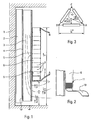
- Figure 1 shows an electrical transformer MV / LV three-phase dry insulation for installation indoors or outdoors for the distribution of electrical energy.
- a LV winding 2 is placed and, positioned concentrically with this winding 2, an insulating cylinder 3 having on its surface inside a conductive or semi-conductive layer 4 connected to the earth's potential, and on its surface outer layer of semiconductor material 5 designated RLT, whose function is to provide linear distribution of tension over the entire length of the insulating cylinder.
- RLT semiconductor material 5
- MT 6 winding is positioned directly on the layer of RLT material and covers it the central part. This winding presents the peculiarity of being produced so that the evolution of the potential between the different turns which constitute it is done in a privileged way according to the axial direction.
- the insulating cylinder 3 is made of a material to high dielectric characteristics and obtained by molding, extrusion or any other process allowing to obtain a cylinder free of vacuoles and perfectly homogeneous.
- This material can be a material thermoplastic, like the polyethylene used in the high voltage cables, or a elastomer, silicone or EPDM for example.
- Layer conductive or semi-conductive 4 can be obtained by the projection of a synthetic material charged with a metal powder on the inside diameter of the tube insulator 3.
- Semiconductor materials including permittivity and resistivity vary depending on the electric field are known and used in electrical engineering for the production of accessories high voltage cables, and more particularly in the manufacture of the retractable ends which equip these cables.
- RLT linear distributors of voltage
- layer 5 of RLT material can be obtained by winding a sheet, winding a ribbon, or the shrinking of a pre-molded tube on the diameter outside of the insulating cylinder 3.
- the MT 6 winding is made up of small width pancakes 7, connected between them in series.
- Each of these patties is made up of layers of coils 9 superimposed, produced from a wire of conductive material 8 of circular section coated an insulating varnish.
- the MT winding is obtained using a ribbon 10 in bare conductive material of rectangular section, the material used being chosen for its ductility.
- This ribbon conductor 10 is wound on the field and associated with a film insulator 11 of small thickness.
- the appearance of the electric field resulting from this design mode corresponds to the case of a three-phase transformer whose MT 6 windings are coupled in a triangle, like this is shown in Figure 3.
- the radial electric field located between the winding MT 6 and the LV 2 winding is fully contained in the insulating cylinder 3, between layer 4 connected to the potential of the earth and the RLT layer 5.
- the axial field is distributes on the one hand over the entire axial length of MT 6 winding, and on the other hand at the ends of the insulating cylinder 3 not covered by the MT 6 winding, but nevertheless covered with the layer 5 of RLT material. In these three areas, the field electric radiant in the air is distributed so homogeneous and remains sufficiently reduced to exclude all risk of partial discharge or bypass by electric arc.
- the transformer is entirely coated with a layer 12 of synthetic material having good resistance to ultraviolet rays, electrical tracking, and electrical constraints that could lead to perforation of said coating.
- a layer 12 of synthetic material having good resistance to ultraviolet rays, electrical tracking, and electrical constraints that could lead to perforation of said coating.
- This can be obtained for example by soaking the transformer in a bath, or by spraying with a pneumatic gun, of a material synthetic with the desired characteristics. This also ensures protection against corrosion of mechanical parts and filling the gaps between the different parts of the device.
- Figure 4 shows the transformer described in figure 1 and provided with its coating 12.
- Figure 5 presents a variant whose interest is extend the tracking distance in areas where the electric field radiating in the air is the most dense, and which correspond to the ends of the cylinder insulation not covered by the MV winding.
- rings 13 of insulating material are distributed regularly on the insulating cylinder (13).
- the coating 12 applied to the entire sealed transformer the contact zone between the rings 13 and the layer 5 of RLT material and thus makes skirts identical to those that would include an electrical insulator.
Landscapes
- Engineering & Computer Science (AREA)
- Power Engineering (AREA)
- Insulating Of Coils (AREA)
- Insulation, Fastening Of Motor, Generator Windings (AREA)
- Organic Insulating Materials (AREA)
Abstract
Description
- La figure 1 représente une coupe verticale d'un premier mode de réalisation d'un transformateur conforme à l'invention,
- la figure 2 représente une coupe verticale d'un deuxième mode de réalisation d'un transformateur conforme à l'invention,
- la figure 3 représente un exemple de couplage des enroulements d'un transformateur triphasé conforme à l'invention,
- la figure 4 représente schématiquement une variante du transformateur représenté à la figure 1.
- la figure 5 représente schématiquement une deuxième variante du transformateur représenté à la figure 1.
Claims (5)
- Transformateur électrique MT/BT mono ou polyphasé, à isolement de type sec, destiné à une installation en intérieur ou en extérieur, caractérisé par le fait qu'il comporte pour chacune de ses phases un cylindre isolant (3) situé entre l'enroulement BT (2) et l'enroulement MT (6), et en ce que ce cylindre (3) est revêtu sur sa surface intérieure d'une couche conductrice ou semi-conductrice (4) portée au potentiel de la terre, et sur sa surface extérieure d'une couche en matériau semi-conducteur répartiteur linéaire de tension (5) sur laquelle est bobiné localement l'enroulement MT (2).
- Transformateur conforme à la revendication 1, caractérisé en ce que l'enroulement MT (6) présente une structure en galettes de faible largeur, constituées d'une superposition de couches de spires (9), et raccordées en série, de telle manière que la répartition du potentiel dans ledit enroulement (6) soit de type axial.
- Transformateur conforme à la revendication 1, caractérisé par le fait que l'enroulement MT (6) est constitué par le bobinage sur champ d'un ruban (10) de conducteur en association avec un film de matériau isolant (11), de telle manière que la répartition du potentiel dans ledit enroulement soit de type axial.
- Transformateur conforme à la revendication 1, caractérisé par le fait qu'il comporte un revêtement (12) uniforme constitué par une couche en matériau synthétique présentant des caractéristiques électriques et physiques adéquates pour une utilisation en extérieur, ce revêtement (12) pouvant être obtenu par trempage ou par projection.
- Transformateur conforme à la revendication 4, caractérisé par le fait qu'il comporte, de part et d'autre de l'enroulement MT, des anneaux (13) en matériau isolant constituant des jupes destinées à allonger les distances de cheminement électrique entre l'enroulement MT (6) et les parties liées au potentiel de masse dudit transformateur, lesdites jupes étant situées sur le cylindre isolant (3) revêtu de la couche en matériau semi-conducteur répartiteur linéaire de tension et étant recouvertes du revêtement isolant (12) appliqué sur l'ensemble du transformateur.
Applications Claiming Priority (2)
| Application Number | Priority Date | Filing Date | Title |
|---|---|---|---|
| FR9905938 | 1999-05-10 | ||
| FR9905938A FR2793599B1 (fr) | 1999-05-10 | 1999-05-10 | Transformateur mt/bt a isolement sec, a champ electrique lineairement reparti, pour la distribution de l'energie electrique en milieu rural |
Publications (2)
| Publication Number | Publication Date |
|---|---|
| EP1052659A1 true EP1052659A1 (fr) | 2000-11-15 |
| EP1052659B1 EP1052659B1 (fr) | 2008-08-13 |
Family
ID=9545413
Family Applications (1)
| Application Number | Title | Priority Date | Filing Date |
|---|---|---|---|
| EP00401081A Expired - Lifetime EP1052659B1 (fr) | 1999-05-10 | 2000-04-18 | Transformateur MT/BT à isolement sec, à champ électrique linéairement réparti, pour la distribution de l'énergie électrique en milieu rural |
Country Status (5)
| Country | Link |
|---|---|
| EP (1) | EP1052659B1 (fr) |
| AT (1) | ATE404984T1 (fr) |
| DE (1) | DE60039813D1 (fr) |
| ES (1) | ES2312326T3 (fr) |
| FR (1) | FR2793599B1 (fr) |
Cited By (2)
| Publication number | Priority date | Publication date | Assignee | Title |
|---|---|---|---|---|
| WO2008095660A1 (fr) * | 2007-02-07 | 2008-08-14 | Hanser Volker W | Transformateur |
| CN108987038A (zh) * | 2017-05-31 | 2018-12-11 | 台达电子工业股份有限公司 | 磁性组件 |
Citations (3)
| Publication number | Priority date | Publication date | Assignee | Title |
|---|---|---|---|---|
| DE2150214A1 (de) * | 1971-10-08 | 1973-04-12 | Transformatoren Union Ag | Mit einem schild versehene wicklung fuer transformatoren |
| US4518941A (en) * | 1983-11-16 | 1985-05-21 | Nihon Kohden Corporation | Pulse transformer for switching power supplies |
| WO1997045847A1 (fr) * | 1996-05-29 | 1997-12-04 | Asea Brown Boveri Ab | Transformateur/reacteur |
-
1999
- 1999-05-10 FR FR9905938A patent/FR2793599B1/fr not_active Expired - Fee Related
-
2000
- 2000-04-18 AT AT00401081T patent/ATE404984T1/de not_active IP Right Cessation
- 2000-04-18 DE DE60039813T patent/DE60039813D1/de not_active Expired - Fee Related
- 2000-04-18 ES ES00401081T patent/ES2312326T3/es not_active Expired - Lifetime
- 2000-04-18 EP EP00401081A patent/EP1052659B1/fr not_active Expired - Lifetime
Patent Citations (3)
| Publication number | Priority date | Publication date | Assignee | Title |
|---|---|---|---|---|
| DE2150214A1 (de) * | 1971-10-08 | 1973-04-12 | Transformatoren Union Ag | Mit einem schild versehene wicklung fuer transformatoren |
| US4518941A (en) * | 1983-11-16 | 1985-05-21 | Nihon Kohden Corporation | Pulse transformer for switching power supplies |
| WO1997045847A1 (fr) * | 1996-05-29 | 1997-12-04 | Asea Brown Boveri Ab | Transformateur/reacteur |
Cited By (3)
| Publication number | Priority date | Publication date | Assignee | Title |
|---|---|---|---|---|
| WO2008095660A1 (fr) * | 2007-02-07 | 2008-08-14 | Hanser Volker W | Transformateur |
| EA015163B1 (ru) * | 2007-02-07 | 2011-06-30 | Фолькер В. Ханзер | Трансформатор |
| CN108987038A (zh) * | 2017-05-31 | 2018-12-11 | 台达电子工业股份有限公司 | 磁性组件 |
Also Published As
| Publication number | Publication date |
|---|---|
| ATE404984T1 (de) | 2008-08-15 |
| FR2793599B1 (fr) | 2001-07-06 |
| FR2793599A1 (fr) | 2000-11-17 |
| EP1052659B1 (fr) | 2008-08-13 |
| DE60039813D1 (de) | 2008-09-25 |
| ES2312326T3 (es) | 2009-03-01 |
Similar Documents
| Publication | Publication Date | Title |
|---|---|---|
| EP3069354A1 (fr) | Procédé de fabrication de câbles électriques et câble électrique associé | |
| EP2062268B1 (fr) | Support isolant pour dispositif haute- ou moyenne- tension et dispositif le comprenant | |
| EP1052659B1 (fr) | Transformateur MT/BT à isolement sec, à champ électrique linéairement réparti, pour la distribution de l'énergie électrique en milieu rural | |
| EP1366499B1 (fr) | Materiau isolant pour surmoulage sur appareils moyenne et haute tension, et appareils electriques moyenne et haute tension utilisant un tel materiau | |
| EP1166287B1 (fr) | Procede de fabrication de parafoudres et parafoudre a base de varistances electriques | |
| EP0248717B1 (fr) | Bobine électromagnétique et dispositif d'allumage pour moteur à combustion interne comportant une telle bobine | |
| FR2637729A1 (fr) | Transformateur de distribution haute tension/basse tension a isolement sec et procede pour realiser un tel transformateur | |
| EP0860835A1 (fr) | Fil émaillé de résistance élevée aux décharges partielles | |
| FR2883425A1 (fr) | Extremite synthetique de cable electrique pour tension continue | |
| CA2285806C (fr) | Transformateur sec de puissance ou de distribution de l'energie electrique | |
| FR2679695A1 (fr) | Ampoule sous vide pourvue d'une isolation electrique. | |
| EP0115322B1 (fr) | Dispositif moulé recouvrant une extrémité d'un câble électrique moyenne tension | |
| EP0007584A1 (fr) | Extrémité de câble électrique | |
| CH669277A5 (en) | High tension electric cable with extruded insulating layers - consists of synthetic materials of different dielectric properties sandwiched between 2 semiconducting layers | |
| WO2023118709A1 (fr) | Terminaison d'un câble de transport électrique à haute ou très haute tension et procédé de préparation d'une terminaison d'une extrémité de câble | |
| FR2723245A1 (fr) | Cable de transport d'energie electrique ou de telecommunication et procede de fabrication d'un tel cable | |
| EP0494807B1 (fr) | Borne haute tension de raccordement | |
| FR2735898A1 (fr) | Procede de fabrication d'un isolateur en materiau composite | |
| CH277798A (fr) | Tube résistant à l'humidité. | |
| FR2852746A1 (fr) | Systeme de transmission d'energie a haute tension | |
| FR2461385A2 (fr) | Dispositif de protection d'arret d'ecran pour cable electrique | |
| EP1016165A1 (fr) | Cable rayonnant | |
| CH266744A (fr) | Procédé de fabrication d'un joint de câble avec cône de répartition, notamment pour câble électrique á haute tension. | |
| FR2635419A1 (fr) | Dispositif de reduction de courant de gaine | |
| EP1031176A1 (fr) | Manchon repartiteur de tension pour un c ble electrique haute tension |
Legal Events
| Date | Code | Title | Description |
|---|---|---|---|
| PUAI | Public reference made under article 153(3) epc to a published international application that has entered the european phase |
Free format text: ORIGINAL CODE: 0009012 |
|
| AK | Designated contracting states |
Kind code of ref document: A1 Designated state(s): AT BE CH CY DE DK ES FI FR GB GR IE IT LI LU MC NL PT SE |
|
| AX | Request for extension of the european patent |
Free format text: AL;LT;LV;MK;RO;SI |
|
| 17P | Request for examination filed |
Effective date: 20010417 |
|
| AKX | Designation fees paid |
Free format text: AT BE CH CY DE DK ES FI FR GB GR IE IT LI LU MC NL PT SE |
|
| GRAP | Despatch of communication of intention to grant a patent |
Free format text: ORIGINAL CODE: EPIDOSNIGR1 |
|
| GRAS | Grant fee paid |
Free format text: ORIGINAL CODE: EPIDOSNIGR3 |
|
| GRAA | (expected) grant |
Free format text: ORIGINAL CODE: 0009210 |
|
| AK | Designated contracting states |
Kind code of ref document: B1 Designated state(s): AT BE CH CY DE DK ES FI FR GB GR IE IT LI LU MC NL PT SE |
|
| REG | Reference to a national code |
Ref country code: GB Ref legal event code: FG4D Free format text: NOT ENGLISH |
|
| REG | Reference to a national code |
Ref country code: CH Ref legal event code: EP |
|
| REG | Reference to a national code |
Ref country code: IE Ref legal event code: FG4D Free format text: LANGUAGE OF EP DOCUMENT: FRENCH |
|
| REF | Corresponds to: |
Ref document number: 60039813 Country of ref document: DE Date of ref document: 20080925 Kind code of ref document: P |
|
| PG25 | Lapsed in a contracting state [announced via postgrant information from national office to epo] |
Ref country code: NL Free format text: LAPSE BECAUSE OF FAILURE TO SUBMIT A TRANSLATION OF THE DESCRIPTION OR TO PAY THE FEE WITHIN THE PRESCRIBED TIME-LIMIT Effective date: 20080813 |
|
| PG25 | Lapsed in a contracting state [announced via postgrant information from national office to epo] |
Ref country code: FI Free format text: LAPSE BECAUSE OF FAILURE TO SUBMIT A TRANSLATION OF THE DESCRIPTION OR TO PAY THE FEE WITHIN THE PRESCRIBED TIME-LIMIT Effective date: 20080813 Ref country code: AT Free format text: LAPSE BECAUSE OF FAILURE TO SUBMIT A TRANSLATION OF THE DESCRIPTION OR TO PAY THE FEE WITHIN THE PRESCRIBED TIME-LIMIT Effective date: 20080813 |
|
| REG | Reference to a national code |
Ref country code: ES Ref legal event code: FG2A Ref document number: 2312326 Country of ref document: ES Kind code of ref document: T3 |
|
| REG | Reference to a national code |
Ref country code: IE Ref legal event code: FD4D |
|
| PG25 | Lapsed in a contracting state [announced via postgrant information from national office to epo] |
Ref country code: DK Free format text: LAPSE BECAUSE OF FAILURE TO SUBMIT A TRANSLATION OF THE DESCRIPTION OR TO PAY THE FEE WITHIN THE PRESCRIBED TIME-LIMIT Effective date: 20080813 Ref country code: IE Free format text: LAPSE BECAUSE OF FAILURE TO SUBMIT A TRANSLATION OF THE DESCRIPTION OR TO PAY THE FEE WITHIN THE PRESCRIBED TIME-LIMIT Effective date: 20080813 |
|
| PG25 | Lapsed in a contracting state [announced via postgrant information from national office to epo] |
Ref country code: PT Free format text: LAPSE BECAUSE OF FAILURE TO SUBMIT A TRANSLATION OF THE DESCRIPTION OR TO PAY THE FEE WITHIN THE PRESCRIBED TIME-LIMIT Effective date: 20090113 |
|
| PLBE | No opposition filed within time limit |
Free format text: ORIGINAL CODE: 0009261 |
|
| STAA | Information on the status of an ep patent application or granted ep patent |
Free format text: STATUS: NO OPPOSITION FILED WITHIN TIME LIMIT |
|
| 26N | No opposition filed |
Effective date: 20090514 |
|
| PGFP | Annual fee paid to national office [announced via postgrant information from national office to epo] |
Ref country code: ES Payment date: 20090508 Year of fee payment: 10 |
|
| PGFP | Annual fee paid to national office [announced via postgrant information from national office to epo] |
Ref country code: DE Payment date: 20090420 Year of fee payment: 10 Ref country code: IT Payment date: 20090421 Year of fee payment: 10 |
|
| PGFP | Annual fee paid to national office [announced via postgrant information from national office to epo] |
Ref country code: BE Payment date: 20090417 Year of fee payment: 10 |
|
| PGFP | Annual fee paid to national office [announced via postgrant information from national office to epo] |
Ref country code: GB Payment date: 20090415 Year of fee payment: 10 |
|
| REG | Reference to a national code |
Ref country code: CH Ref legal event code: PL |
|
| PG25 | Lapsed in a contracting state [announced via postgrant information from national office to epo] |
Ref country code: CH Free format text: LAPSE BECAUSE OF NON-PAYMENT OF DUE FEES Effective date: 20090430 Ref country code: LI Free format text: LAPSE BECAUSE OF NON-PAYMENT OF DUE FEES Effective date: 20090430 Ref country code: SE Free format text: LAPSE BECAUSE OF FAILURE TO SUBMIT A TRANSLATION OF THE DESCRIPTION OR TO PAY THE FEE WITHIN THE PRESCRIBED TIME-LIMIT Effective date: 20081113 |
|
| PG25 | Lapsed in a contracting state [announced via postgrant information from national office to epo] |
Ref country code: MC Free format text: LAPSE BECAUSE OF NON-PAYMENT OF DUE FEES Effective date: 20090430 |
|
| PG25 | Lapsed in a contracting state [announced via postgrant information from national office to epo] |
Ref country code: GR Free format text: LAPSE BECAUSE OF FAILURE TO SUBMIT A TRANSLATION OF THE DESCRIPTION OR TO PAY THE FEE WITHIN THE PRESCRIBED TIME-LIMIT Effective date: 20081114 |
|
| BERE | Be: lapsed |
Owner name: SOC. NOUVELLE TRANSFIX TOULON Effective date: 20100430 |
|
| GBPC | Gb: european patent ceased through non-payment of renewal fee |
Effective date: 20100418 |
|
| PG25 | Lapsed in a contracting state [announced via postgrant information from national office to epo] |
Ref country code: DE Free format text: LAPSE BECAUSE OF NON-PAYMENT OF DUE FEES Effective date: 20101103 |
|
| PG25 | Lapsed in a contracting state [announced via postgrant information from national office to epo] |
Ref country code: IT Free format text: LAPSE BECAUSE OF NON-PAYMENT OF DUE FEES Effective date: 20100418 Ref country code: BE Free format text: LAPSE BECAUSE OF NON-PAYMENT OF DUE FEES Effective date: 20100430 Ref country code: GB Free format text: LAPSE BECAUSE OF NON-PAYMENT OF DUE FEES Effective date: 20100418 |
|
| PG25 | Lapsed in a contracting state [announced via postgrant information from national office to epo] |
Ref country code: LU Free format text: LAPSE BECAUSE OF NON-PAYMENT OF DUE FEES Effective date: 20090418 |
|
| REG | Reference to a national code |
Ref country code: ES Ref legal event code: FD2A Effective date: 20110714 |
|
| PG25 | Lapsed in a contracting state [announced via postgrant information from national office to epo] |
Ref country code: ES Free format text: LAPSE BECAUSE OF NON-PAYMENT OF DUE FEES Effective date: 20110704 |
|
| PG25 | Lapsed in a contracting state [announced via postgrant information from national office to epo] |
Ref country code: CY Free format text: LAPSE BECAUSE OF FAILURE TO SUBMIT A TRANSLATION OF THE DESCRIPTION OR TO PAY THE FEE WITHIN THE PRESCRIBED TIME-LIMIT Effective date: 20080813 Ref country code: ES Free format text: LAPSE BECAUSE OF NON-PAYMENT OF DUE FEES Effective date: 20100419 |
|
| REG | Reference to a national code |
Ref country code: FR Ref legal event code: CD Owner name: TRANSFIX, FR Effective date: 20131129 Ref country code: FR Ref legal event code: CA Effective date: 20131129 |
|
| REG | Reference to a national code |
Ref country code: FR Ref legal event code: PLFP Year of fee payment: 17 |
|
| REG | Reference to a national code |
Ref country code: FR Ref legal event code: PLFP Year of fee payment: 18 |
|
| REG | Reference to a national code |
Ref country code: FR Ref legal event code: PLFP Year of fee payment: 19 |
|
| PGFP | Annual fee paid to national office [announced via postgrant information from national office to epo] |
Ref country code: FR Payment date: 20180323 Year of fee payment: 19 |
|
| PG25 | Lapsed in a contracting state [announced via postgrant information from national office to epo] |
Ref country code: FR Free format text: LAPSE BECAUSE OF NON-PAYMENT OF DUE FEES Effective date: 20190430 |