EP1052745A2 - Filtre optique - Google Patents
Filtre optique Download PDFInfo
- Publication number
- EP1052745A2 EP1052745A2 EP00810102A EP00810102A EP1052745A2 EP 1052745 A2 EP1052745 A2 EP 1052745A2 EP 00810102 A EP00810102 A EP 00810102A EP 00810102 A EP00810102 A EP 00810102A EP 1052745 A2 EP1052745 A2 EP 1052745A2
- Authority
- EP
- European Patent Office
- Prior art keywords
- filter
- optical
- face
- etalon
- slope
- Prior art date
- Legal status (The legal status is an assumption and is not a legal conclusion. Google has not performed a legal analysis and makes no representation as to the accuracy of the status listed.)
- Withdrawn
Links
- 230000003287 optical effect Effects 0.000 title claims abstract description 55
- BJQHLKABXJIVAM-UHFFFAOYSA-N bis(2-ethylhexyl) phthalate Chemical compound CCCCC(CC)COC(=O)C1=CC=CC=C1C(=O)OCC(CC)CCCC BJQHLKABXJIVAM-UHFFFAOYSA-N 0.000 claims abstract description 51
- 230000004044 response Effects 0.000 claims abstract description 47
- 238000000034 method Methods 0.000 claims abstract description 7
- 238000001914 filtration Methods 0.000 claims abstract 2
- 238000002310 reflectometry Methods 0.000 claims description 22
- 238000001228 spectrum Methods 0.000 claims description 14
- 230000003595 spectral effect Effects 0.000 claims description 12
- 230000007246 mechanism Effects 0.000 claims description 2
- 230000001902 propagating effect Effects 0.000 claims 1
- 230000008859 change Effects 0.000 description 12
- 229910052691 Erbium Inorganic materials 0.000 description 9
- 239000000470 constituent Substances 0.000 description 9
- UYAHIZSMUZPPFV-UHFFFAOYSA-N erbium Chemical compound [Er] UYAHIZSMUZPPFV-UHFFFAOYSA-N 0.000 description 9
- 239000000835 fiber Substances 0.000 description 9
- 239000011521 glass Substances 0.000 description 8
- 239000000758 substrate Substances 0.000 description 8
- 230000005540 biological transmission Effects 0.000 description 5
- 239000013307 optical fiber Substances 0.000 description 4
- 239000010409 thin film Substances 0.000 description 4
- 102100027004 Inhibin beta A chain Human genes 0.000 description 3
- 239000011248 coating agent Substances 0.000 description 3
- 238000000576 coating method Methods 0.000 description 3
- 238000010586 diagram Methods 0.000 description 3
- 239000000463 material Substances 0.000 description 3
- 239000004593 Epoxy Substances 0.000 description 2
- 239000002019 doping agent Substances 0.000 description 2
- 230000000694 effects Effects 0.000 description 2
- 239000000146 host glass Substances 0.000 description 2
- 239000000203 mixture Substances 0.000 description 2
- 230000000737 periodic effect Effects 0.000 description 2
- 238000005086 pumping Methods 0.000 description 2
- VYPSYNLAJGMNEJ-UHFFFAOYSA-N Silicium dioxide Chemical compound O=[Si]=O VYPSYNLAJGMNEJ-UHFFFAOYSA-N 0.000 description 1
- PNEYBMLMFCGWSK-UHFFFAOYSA-N aluminium oxide Inorganic materials [O-2].[O-2].[O-2].[Al+3].[Al+3] PNEYBMLMFCGWSK-UHFFFAOYSA-N 0.000 description 1
- 230000003190 augmentative effect Effects 0.000 description 1
- 238000004891 communication Methods 0.000 description 1
- 229910052593 corundum Inorganic materials 0.000 description 1
- 230000008878 coupling Effects 0.000 description 1
- 238000010168 coupling process Methods 0.000 description 1
- 238000005859 coupling reaction Methods 0.000 description 1
- 230000002939 deleterious effect Effects 0.000 description 1
- 230000001419 dependent effect Effects 0.000 description 1
- 239000006185 dispersion Substances 0.000 description 1
- 238000006073 displacement reaction Methods 0.000 description 1
- 239000003365 glass fiber Substances 0.000 description 1
- 150000002500 ions Chemical class 0.000 description 1
- 230000010287 polarization Effects 0.000 description 1
- 230000000644 propagated effect Effects 0.000 description 1
- 229910052761 rare earth metal Inorganic materials 0.000 description 1
- 150000002910 rare earth metals Chemical class 0.000 description 1
- 239000000523 sample Substances 0.000 description 1
- 238000000638 solvent extraction Methods 0.000 description 1
- 229910001845 yogo sapphire Inorganic materials 0.000 description 1
Images


Classifications
-
- H—ELECTRICITY
- H04—ELECTRIC COMMUNICATION TECHNIQUE
- H04B—TRANSMISSION
- H04B10/00—Transmission systems employing electromagnetic waves other than radio-waves, e.g. infrared, visible or ultraviolet light, or employing corpuscular radiation, e.g. quantum communication
- H04B10/29—Repeaters
- H04B10/291—Repeaters in which processing or amplification is carried out without conversion of the main signal from optical form
- H04B10/2912—Repeaters in which processing or amplification is carried out without conversion of the main signal from optical form characterised by the medium used for amplification or processing
-
- G—PHYSICS
- G02—OPTICS
- G02B—OPTICAL ELEMENTS, SYSTEMS OR APPARATUS
- G02B5/00—Optical elements other than lenses
- G02B5/20—Filters
- G02B5/28—Interference filters
- G02B5/284—Interference filters of etalon type comprising a resonant cavity other than a thin solid film, e.g. gas, air, solid plates
-
- G—PHYSICS
- G02—OPTICS
- G02B—OPTICAL ELEMENTS, SYSTEMS OR APPARATUS
- G02B6/00—Light guides; Structural details of arrangements comprising light guides and other optical elements, e.g. couplings
- G02B6/24—Coupling light guides
- G02B6/26—Optical coupling means
- G02B6/28—Optical coupling means having data bus means, i.e. plural waveguides interconnected and providing an inherently bidirectional system by mixing and splitting signals
- G02B6/293—Optical coupling means having data bus means, i.e. plural waveguides interconnected and providing an inherently bidirectional system by mixing and splitting signals with wavelength selective means
- G02B6/29346—Optical coupling means having data bus means, i.e. plural waveguides interconnected and providing an inherently bidirectional system by mixing and splitting signals with wavelength selective means operating by wave or beam interference
- G02B6/29361—Interference filters, e.g. multilayer coatings, thin film filters, dichroic splitters or mirrors based on multilayers, WDM filters
- G02B6/29362—Serial cascade of filters or filtering operations, e.g. for a large number of channels
- G02B6/29364—Cascading by a light guide path between filters or filtering operations, e.g. fibre interconnected single filter modules
-
- G—PHYSICS
- G02—OPTICS
- G02B—OPTICAL ELEMENTS, SYSTEMS OR APPARATUS
- G02B6/00—Light guides; Structural details of arrangements comprising light guides and other optical elements, e.g. couplings
- G02B6/24—Coupling light guides
- G02B6/26—Optical coupling means
- G02B6/28—Optical coupling means having data bus means, i.e. plural waveguides interconnected and providing an inherently bidirectional system by mixing and splitting signals
- G02B6/293—Optical coupling means having data bus means, i.e. plural waveguides interconnected and providing an inherently bidirectional system by mixing and splitting signals with wavelength selective means
- G02B6/29346—Optical coupling means having data bus means, i.e. plural waveguides interconnected and providing an inherently bidirectional system by mixing and splitting signals with wavelength selective means operating by wave or beam interference
- G02B6/29361—Interference filters, e.g. multilayer coatings, thin film filters, dichroic splitters or mirrors based on multilayers, WDM filters
- G02B6/2937—In line lens-filtering-lens devices, i.e. elements arranged along a line and mountable in a cylindrical package for compactness, e.g. 3- port device with GRIN lenses sandwiching a single filter operating at normal incidence in a tubular package
-
- G—PHYSICS
- G02—OPTICS
- G02B—OPTICAL ELEMENTS, SYSTEMS OR APPARATUS
- G02B6/00—Light guides; Structural details of arrangements comprising light guides and other optical elements, e.g. couplings
- G02B6/24—Coupling light guides
- G02B6/26—Optical coupling means
- G02B6/28—Optical coupling means having data bus means, i.e. plural waveguides interconnected and providing an inherently bidirectional system by mixing and splitting signals
- G02B6/293—Optical coupling means having data bus means, i.e. plural waveguides interconnected and providing an inherently bidirectional system by mixing and splitting signals with wavelength selective means
- G02B6/29379—Optical coupling means having data bus means, i.e. plural waveguides interconnected and providing an inherently bidirectional system by mixing and splitting signals with wavelength selective means characterised by the function or use of the complete device
- G02B6/29391—Power equalisation of different channels, e.g. power flattening
-
- G—PHYSICS
- G02—OPTICS
- G02B—OPTICAL ELEMENTS, SYSTEMS OR APPARATUS
- G02B6/00—Light guides; Structural details of arrangements comprising light guides and other optical elements, e.g. couplings
- G02B6/24—Coupling light guides
- G02B6/26—Optical coupling means
- G02B6/28—Optical coupling means having data bus means, i.e. plural waveguides interconnected and providing an inherently bidirectional system by mixing and splitting signals
- G02B6/293—Optical coupling means having data bus means, i.e. plural waveguides interconnected and providing an inherently bidirectional system by mixing and splitting signals with wavelength selective means
- G02B6/29379—Optical coupling means having data bus means, i.e. plural waveguides interconnected and providing an inherently bidirectional system by mixing and splitting signals with wavelength selective means characterised by the function or use of the complete device
- G02B6/29395—Optical coupling means having data bus means, i.e. plural waveguides interconnected and providing an inherently bidirectional system by mixing and splitting signals with wavelength selective means characterised by the function or use of the complete device configurable, e.g. tunable or reconfigurable
-
- H—ELECTRICITY
- H01—ELECTRIC ELEMENTS
- H01S—DEVICES USING THE PROCESS OF LIGHT AMPLIFICATION BY STIMULATED EMISSION OF RADIATION [LASER] TO AMPLIFY OR GENERATE LIGHT; DEVICES USING STIMULATED EMISSION OF ELECTROMAGNETIC RADIATION IN WAVE RANGES OTHER THAN OPTICAL
- H01S3/00—Lasers, i.e. devices using stimulated emission of electromagnetic radiation in the infrared, visible or ultraviolet wave range
- H01S3/10—Controlling the intensity, frequency, phase, polarisation or direction of the emitted radiation, e.g. switching, gating, modulating or demodulating
- H01S3/10007—Controlling the intensity, frequency, phase, polarisation or direction of the emitted radiation, e.g. switching, gating, modulating or demodulating in optical amplifiers
- H01S3/10023—Controlling the intensity, frequency, phase, polarisation or direction of the emitted radiation, e.g. switching, gating, modulating or demodulating in optical amplifiers by functional association of additional optical elements, e.g. filters, gratings, reflectors
-
- H—ELECTRICITY
- H04—ELECTRIC COMMUNICATION TECHNIQUE
- H04B—TRANSMISSION
- H04B10/00—Transmission systems employing electromagnetic waves other than radio-waves, e.g. infrared, visible or ultraviolet light, or employing corpuscular radiation, e.g. quantum communication
- H04B10/29—Repeaters
- H04B10/291—Repeaters in which processing or amplification is carried out without conversion of the main signal from optical form
- H04B10/293—Signal power control
- H04B10/294—Signal power control in a multiwavelength system, e.g. gain equalisation
- H04B10/2941—Signal power control in a multiwavelength system, e.g. gain equalisation using an equalising unit, e.g. a filter
-
- H—ELECTRICITY
- H01—ELECTRIC ELEMENTS
- H01S—DEVICES USING THE PROCESS OF LIGHT AMPLIFICATION BY STIMULATED EMISSION OF RADIATION [LASER] TO AMPLIFY OR GENERATE LIGHT; DEVICES USING STIMULATED EMISSION OF ELECTROMAGNETIC RADIATION IN WAVE RANGES OTHER THAN OPTICAL
- H01S2301/00—Functional characteristics
- H01S2301/04—Gain spectral shaping, flattening
-
- H—ELECTRICITY
- H01—ELECTRIC ELEMENTS
- H01S—DEVICES USING THE PROCESS OF LIGHT AMPLIFICATION BY STIMULATED EMISSION OF RADIATION [LASER] TO AMPLIFY OR GENERATE LIGHT; DEVICES USING STIMULATED EMISSION OF ELECTROMAGNETIC RADIATION IN WAVE RANGES OTHER THAN OPTICAL
- H01S2301/00—Functional characteristics
- H01S2301/06—Gain non-linearity, distortion; Compensation thereof
-
- H—ELECTRICITY
- H01—ELECTRIC ELEMENTS
- H01S—DEVICES USING THE PROCESS OF LIGHT AMPLIFICATION BY STIMULATED EMISSION OF RADIATION [LASER] TO AMPLIFY OR GENERATE LIGHT; DEVICES USING STIMULATED EMISSION OF ELECTROMAGNETIC RADIATION IN WAVE RANGES OTHER THAN OPTICAL
- H01S3/00—Lasers, i.e. devices using stimulated emission of electromagnetic radiation in the infrared, visible or ultraviolet wave range
- H01S3/14—Lasers, i.e. devices using stimulated emission of electromagnetic radiation in the infrared, visible or ultraviolet wave range characterised by the material used as the active medium
- H01S3/16—Solid materials
- H01S3/1601—Solid materials characterised by an active (lasing) ion
- H01S3/1603—Solid materials characterised by an active (lasing) ion rare earth
- H01S3/1608—Solid materials characterised by an active (lasing) ion rare earth erbium
Definitions
- This invention relates to a variable reflectivity filter, and more particularly to an etalon having one or more end faces having a variable reflectance.
- Fabry-Perôt filters are widely used in optical systems where a dependence upon their periodic nature is required.
- comb filters are now being developed wherein one or more etalons provide one or more output signals that are periodic in amplitude response.
- the free-spectral range, or period of a Fabry-Perot etalon is determined by a length of a gap between its two reflecting surfaces.
- a multi-port tunable fiber-optic etalon filter having two spaced partially reflective mirrors is disclosed in U.S. Patent No. 5,283,845 in the name of Ip assigned to JDS Fitel Inc..
- This filter has three or more ports, with at least two on one side and at least one on the other side of the etalon.
- a single signal can be filtered with the reflected signal being received, forming a wavelength division multiplexor, or a plurality of signals can be filtered, with or without the reflected signals being received.
- Ip provides a filter wherein the FSR is tunable within a range.
- the intensity of a reference signal derived from an input signal is compared with an output from the Fabry-Perôt etalon to provide a feedback signal that corresponds to the frequency of the input signal.
- the system is calibrated before wavelength locking is performed to determine a ratio of intensities that determines a locked state or condition.
- U.S. Patent No. 5,283,845 Another type of etalon that differs from a fixed etalon, or even a tunable etalon as is described by Ip in U.S. Patent No. 5,283,845 is one wherein the finesse or reflectivity of one or more of the reflectors is variable.
- Such a filter is described in U.S. Patent No. 5,452,121 in the name of Hilgeman assigned to Northrop Grumman Corporation and is said to be useful as a spectral resolution agile filter.
- the instant invention provides an etalon having a variable finesse over the length of at least one reflector.
- One particular use for a filter of this type is in the field of optical amplifiers and more particularly for gain tilt control.
- Optical amplifiers and particularly erbium doped optical fiber amplifiers are nearly ubiquitous in optical transmission systems, particularly in the field of telecommunications.
- Erbium doped fiber amplifiers (EDFAs) have high polarization insensitive gain, low cross talk between signals of different wavelengths, good saturation output power, and a noise figure close to the fundamental quantum limit. The excellent noise characteristics allow hundreds of these amplifiers to be cascaded to cover spans of thousands of kilometers of optical fibre.
- EDFAs as opposed to electronic repeaters are also transparent to data rate, signal format, and wavelength over a limited range, making them useful for wavelength multiplexed (WDM) communication systems that simultaneously transmit a large number of signals using different wavelength bands for each signal.
- WDM wavelength multiplexed
- a disadvantage associated with EDFAs is their narrow spectral width and uneven gain band.
- the useful telecommunications window of an EDFA is approximately 20-30 nm wide, while an ideal amplifier would have a flat spectral gain across the full spectrum which extends form approximately 1520 nm to 1570 nm.
- the peak wavelength of the erbium gain spectrum varies from about 1530 nm to about 1535 nm depending upon the host glass material.
- Fig. 1 shows the characteristic gain spectrum of a particular conventional EDFA where it can be seen that the gain as a function of wavelength varies; this variation will be referred to hereinafter as gain ripple. Numerous techniques have been published for widening and flattening the gain spectrum (i.e.
- reducing the ripple and include for example co-doping an erbium-doped silica glass fibre with Al 2 O 3 ; changing the host glass material itself; using various forms of attenuating filters to reduce the gain at the emission peak; and, constructing hybrid devices having two or more different types of serially connected erbium doped fibre and actively adjusting pump conditions independently in each fibre section to compensate for the different gain slopes of each fibre.
- dynamic gain tilt means the variation in gain at one wavelength as a result of changing the gain at any other wavelength via a change in input EDFA operating conditions.
- a hybrid fibre device having cascaded amplifying stages with different gain spectra and an equal number of pump sources to allow the gain spectra of the individual stages to be effectively tuned independently so that when the total gain is changed, the relative contribution of each stage can be adjusted to arrive at the desired gain, with a resulting gain spectrum having a minimal amount of spectral distortion over the selected wavelength band.
- an erbium doped fibre having a positive gain slope may be combined with a different erbium doped fibre having a negative gain slope such that the hybrid device has a nearly flat gain at specific input power conditions.
- the gain slope of each of the constituent states will generally change at different rates when the pump power input to one of the stages is changed.
- the relative gain of each of the constituent gain stages must be readjusted to make the gain slopes compensate each other.
- one skilled in the art would likely cascade two or more different erbium doped fibre compositions and provide a separate pump source for each amplifying stage at an end of each stage so as to minimize the number of splices and make it as convenient as possible to independently control the pump power to each stage.
- this technique for reducing or improving dynamic gain tilt requires a complex control scheme during operation in which the total power of multiple pump sources must be coordinated in order to realize gain slope compensation over a range of different gains (i.e. to change input power while maintaining a fixed target output power).
- the hybrid device has at most one less pumping source than the number of constituent waveguides of the device.
- the hybrid device automatically provides a change in the pump distribution among the constituent doped waveguide sections so as to achieve a readjustment of the relative gains of the constituent sections.
- this invention provides constituent EDFs of different co-dopant compositions that provides an automatic change in the pump distribution or partitioning among the constituent EDF sections so as to achieve a readjustment of the relative gains of the constituent EDF sections.
- a Fabry-Perôt etalon having two at least partially reflective end faces, at least one of the end faces having a variable reflectance along its length.
- the variable reflectance may be variable in a continuous linear manner over a particular region, or may be step-wise varied over at least two regions.
- a resonant optical cavity having a free spectral range greater than 20 nm, said cavity having a first end face and an at least second partially reflective end face, the first end face being partially reflective and having a reflectivity along its length which varies by at least 10%.
- a variable slope optical filter for in-line use with an optical amplifier signal, the filter being disposed at an input side, an output side, or within the optical amplifier, the filter having a wavelength response that is substantially linear in slope within a band of operation wavelengths of the amplifier, the slope of the filter in said band of wavelengths being between zero and a only one of a positive or negative number, the filter for passing a band of wavelengths having a centre wavelength ⁇ c and having an amplitude response that has an opposite and counter slope as a function of wavelength to that of the amplifier's gain tilt within the operation band of wavelengths; and, a means for providing relative movement between the filter and the optical amplifier signal to vary the slope of the filter within the band of operation wavelengths.
- relative movement may be actual displacement of one of the filter and the input port or, alternatively, by varying the relative angle between the input port and the filter.
- an optical amplifier having coupled thereto, an optical filter for dynamic and variable gain tilt control for use with the amplifier, the filter in a predetermined wavelength band having a width of at least 10 nm where gain tilt control is required, having a centre wavelength ⁇ c and an amplitude response that has an opposite and counter slope as a function of wavelength to that of the amplifier within the predetermined wavelength band; and, a controller and movement mechanism for varying the slope of the filter in response to a control within the predetermined band, the output response of the filter having a slope throughout the predetermined wavelength band which is always only one of negative and positive.
- Fig. 1 the gain spectrum of a typical EDFA amplifier is shown wherein it can be seen that the gain as a function of wavelength varies.
- the gain spectrum here being the small signal gain that would be measured by a weak probe signal while the operating point of the amplifier is fixed, is constrained to a single parameter family of wavelength dependencies. Therefore if gain of the amplifier at some reference wavelength is changed due to a change in input (i.e. , pump and/or signal power) the amplifier gain at other wavelengths will change by well defined amounts that likely are to be different from the amount of gain change at the reference wavelength.
- the wavelength dependence of the amplifier gain change as of result of an input change is referred to herein as dynamic gain tilt.
- the dynamic gain tilt is a distortion of the amplifier gain spectrum for operating conditions that differ from the operating point for which the amplifier was designed.
- filters have been provided heretofore for offsetting and flattening the gain spectrum of conventional EDFAs.
- providing such a fixed filter does not provide a solution to controlling distortion due to dynamic gain tilt a condition that varies with input power of the input optical signal.
- a filter 10 shown in detail in Fig. 2c has a first region 10a consisting of substantially light transmissive material such as clear glass and a second region 10b juxtaposed to the first region having a dichroic multi-layer interference filter disposed thereon.
- the second region 10b in a preferred embodiment has a sloped transmission response versus wavelength shown in Fig. 2b.
- the dimension of the first and second region should be at least the size of the beam incident upon the filter.
- filter used within this specification should include any medium provides an output signal which alters a characteristic of light incident thereupon.
- the filter is disposed between two graded index (GRIN) lenses 12 in a conventional manner, wherein the lenses are used to collimate light exiting the optical fibre 8a, to provide a collimated beam at the input side of the filter 10, and for focusing the collimated beam that has traversed the filter 10, for coupling the beam into the optical fibre 8b.
- Means for moving the filter 10 along a line coincident with arrows 14a and 14b are provided (not shown in Fig. 2a); such means can conveniently be provided in the form of a stepper motor or alternatively in the form of a piezo-electric actuator. Control circuitry and means for moving the filter in dependence upon the control signal are well known in the art and shall not be described.
- the system in accordance with this invention functions in the following manner.
- the filter 10 When the filter 10 is disposed in a position such that the beam incident thereon passes entirely through the clear portion 10a of the filter 10, the amplitude of the beam as a function of wavelength is essentially unchanged.
- the input beam has a signature or amplitude response such as the spectrum shown in Fig. 1, the output beam that has propagated through the clear portion of the filter 10a will essentially be unaffected and will have the same amplitude response as a function of wavelength.
- an input beam has a positive gain tilt due to a change in power of the input beam, passing this beam through the negatively sloped portion 10b of the filter 10 lessens the effect of the positive gain tilt.
- the filter 10 is positionable and dynamically controlled by an actuator and control circuitry (not shown) such that the filter is positionable at locations along the line defined by the arrows 14a and 14b.
- a beam incident upon the filter 10 passes through more or less of the portion 10b and less or more of the portion 10a, respectively depending upon the position of the actuator.
- the filter 10 is moved into a position such that less of the beam passes through the clear portion 10a of the filter 10 and more of the beam passes through the portion 10b.
- Figs. 3a to 3d illustrates a response of the filter 10 and more particularly 10b as it would filter a beam of light 30 having a diameter of approximately 300 ⁇ m, traversing the filter through the portion 10b, (as is shown in Fig. 3b).
- Fig. 3a illustrates a response of the filter 10 and more particularly 10b as it would filter a beam of light 30 having a diameter of approximately 300 ⁇ m, traversing the filter through the portion 10b, (as is shown in Fig. 3b).
- 3c illustrates a response of the same filter, for a same beam 30 traversing the filter (as is shown in Fig. 3d) through both regions 10a and 10b.
- the absolute value of the slope of the line 32a is greater than the absolute value of the slope of the line 32b since some of the light in Fig. 3d is passing through the clear portion of the filter.
- the filters response is flat, and as more of the light passes through the portion 10b, the absolute value of the slope increases to a maximum, in dependence upon the filter's characteristics.
- a first reflective filter 40 is shown having a first portion that is completely reflective to all wavelengths, and a second portion having a reflection response with wavelength shown in Fig. 4b.
- This embodiment works in a similar manner to the embodiment shown in Fig. 2a, however it is based on reflection rather than transmission.
- a filter having a second portion with negative tilt is shown, however, alternatively a filter with portion with positive tilt can be provided in instances where this is required.
- Fig. 5a illustrates an arrangement similar to that of Fig. 2a, however the filter has a first portion 10c having a response with a positive slope, and a second portion having a response having a negative slope.
- a hybrid filter can be provided wherein a clear portion 10a is provided having at its extremities filters 10b and 10c as have been described.
- Figs 5b and 5c show the output amplitude versus wavelength transmission responses for the filters 10b and 10c respectively.
- a series of cascaded filters of this type can be used as tunable gain flattening filters.
- Fig. 6a shows an embodiment according to the invention wherein three filters 62, 64, and 66 are each tunable and designed to filter a different wavelength band.
- Fig. 6b illustrates the response for the three filters, and a dashed line in the graph illustrates the response of the individual filters. Less attenuation can be provided for any of the three wavelength bands by positioning any of the filters such that the beam traverses some or all of the no-attenuating portion of the filters.
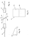
- Fig. 7 a side view of a transmissive filter in accordance with this invention is shown.
- Two glass blocks 70a and 70b are provided having an unattenuating substrate 72a and a thin film coated substrate 72b.
- the inner meeting edges of the two substrates 72a and 72b are polished.
- Between the glass blocks and the substrates 72a and 72b is a refractive index matching epoxy 75.
- Fig. 8 shows a detailed side view of a reflective split filter wherein only a single glass block is required.
- An index matching epoxy is disposed between the glass block 70a and a reflective thin film coated substrate 82b. Adjacent the substrate 82b is a glass substrate 82a having a reflective coating.
- an etalon filter 94 having an input end face 96 coated in such a manner as to have the reflectivity varying substantially linearly along its length in a direction from high reflectivity to lower reflectivity towards the bottom of the filter.
- the difference between the highest reflectivity and the lower reflectivity is greater than 10%.
- the reflectivity might be 55% corresponding to a finesse of approximately 5, and at the lower reflectivity end, where the desired slope may be zero, the corresponding finesse or reflectivity would be zero.
- the opposite end face 97 in this example has a constant reflectivity coating along its length, however is not limited to such.
- the etalon can conveniently made of a single light transmissive block having two at least partially reflective end faces coated end faces.
- the input end face has a coating with a reflectivity which varies along the length thereof, by moving the light beam to be filtered and/or the lens, relatively, light will pass through the etalon such that the etalon will have a different finesse at different relative positions.
- the slope of the output response of the etalon changes within a wavelength range of interest.
- the free spectral range of the etalon must be chosen to provide a suitable window between two different adjacent zero sloping regions of the etalon, and of course the etalon must be tuned or selected to such that the sign (+/-) of the slope is suitable to offset the unwanted tilt of the amplifier to which it is coupled.
- the free spectral range would likely exceed 10 nm, however in other applications it would be preferred to have an etalon with an free spectral range which exceeds 0.5 nm.
- Fig. 9b illustrates three output responses of the filter shown in Fig. 9a for light launched into three locations along the varying reflective end face.
- a first sinusoidal-like wave labeled 90a illustrates the amplitude output response versus wavelength for light launched into location A.
- Fig. 9c is similar to that of Fig. 9a, however the input end face of the etalon has three different discrete portions essentially providing a three-stepped-finesse etalon.
- Fig. 9d shows an etalon wherein each end face has a variable reflectance; here a beam of light incident at a location of the etalon would reflect between two surfaces having a same reflectance, however when the input port is moved by relatively moving at least one of the port and the etalon, the reflectance is varied.
- different regions of the filter may be distinct and different regions, or alternatively may be different regions having some common portions. For example relatively moving an input port and a variable reflectance face of the etalon described heretofore, is considered launching a beam into different regions of the etalon filter.
Landscapes
- Physics & Mathematics (AREA)
- Optics & Photonics (AREA)
- General Physics & Mathematics (AREA)
- Electromagnetism (AREA)
- Engineering & Computer Science (AREA)
- Computer Networks & Wireless Communication (AREA)
- Signal Processing (AREA)
- Spectroscopy & Molecular Physics (AREA)
- Plasma & Fusion (AREA)
- Mechanical Light Control Or Optical Switches (AREA)
- Optical Communication System (AREA)
- Lasers (AREA)
- Optical Filters (AREA)
Applications Claiming Priority (4)
| Application Number | Priority Date | Filing Date | Title |
|---|---|---|---|
| US09/309,489 US6498676B1 (en) | 1998-08-07 | 1999-05-11 | Optical filter for use or with an optical amplifier |
| US309489 | 1999-05-11 | ||
| US363824 | 1999-07-30 | ||
| US09/363,824 US6529328B1 (en) | 1998-08-07 | 1999-07-30 | Optical filter |
Publications (2)
| Publication Number | Publication Date |
|---|---|
| EP1052745A2 true EP1052745A2 (fr) | 2000-11-15 |
| EP1052745A3 EP1052745A3 (fr) | 2001-10-24 |
Family
ID=26976850
Family Applications (1)
| Application Number | Title | Priority Date | Filing Date |
|---|---|---|---|
| EP00810102A Withdrawn EP1052745A3 (fr) | 1999-05-11 | 2000-02-07 | Filtre optique |
Country Status (4)
| Country | Link |
|---|---|
| US (1) | US6529328B1 (fr) |
| EP (1) | EP1052745A3 (fr) |
| JP (1) | JP2000321421A (fr) |
| CA (1) | CA2297538C (fr) |
Cited By (3)
| Publication number | Priority date | Publication date | Assignee | Title |
|---|---|---|---|---|
| US6611371B2 (en) | 2001-03-16 | 2003-08-26 | Corning Incorporated | Single parameter gain slope adjuster for an optical system |
| WO2003079064A1 (fr) * | 2002-03-19 | 2003-09-25 | Dicos Technologies Inc. | Filtre interferentiel a finesses localement differentes |
| US6768579B2 (en) * | 2000-08-18 | 2004-07-27 | Siemens Aktiengesellschaft | Optical amplifier arrangement having a variably settable attenuator |
Families Citing this family (17)
| Publication number | Priority date | Publication date | Assignee | Title |
|---|---|---|---|---|
| US6671296B2 (en) * | 2000-10-10 | 2003-12-30 | Spectrasensors, Inc. | Wavelength locker on optical bench and method of manufacture |
| JP2002280959A (ja) * | 2001-03-16 | 2002-09-27 | Kddi Submarine Cable Systems Inc | 分散補償光伝送路及び光伝送システム |
| JP4199442B2 (ja) | 2001-07-25 | 2008-12-17 | 富士通株式会社 | 波長特性可変装置 |
| US20030118073A1 (en) * | 2001-12-21 | 2003-06-26 | Fsona Communications Corporation | Compact optical amplifier, a system incorporating the same, and an optical amplification method |
| US7035484B2 (en) * | 2002-04-12 | 2006-04-25 | Xtellus, Inc. | Tunable optical filter |
| US20040057477A1 (en) * | 2002-09-24 | 2004-03-25 | Agere Systems Inc. | Wavelength locking device |
| US7295365B2 (en) * | 2005-10-06 | 2007-11-13 | Bookham Technology Plc. | Optical gain flattening components, optical chips and optical amplifiers and methods employing same |
| EP2147488B1 (fr) * | 2007-05-07 | 2014-03-26 | Ludwig-Maximilians-Universität München | Laser accordable |
| CN101374025B (zh) * | 2007-08-22 | 2012-08-29 | 昂纳信息技术(深圳)有限公司 | 光放大器增益平坦滤波器的谱形确定方法 |
| US10677972B2 (en) * | 2017-12-08 | 2020-06-09 | Viavi Solutions Inc. | Multispectral sensor response balancing |
| US11789188B2 (en) * | 2019-07-19 | 2023-10-17 | Viavi Solutions Inc. | Optical filter |
| CN112130241B (zh) * | 2020-09-29 | 2022-11-11 | 苏州众为光电有限公司 | 一种带通滤光片 |
| CN112130243B (zh) * | 2020-09-29 | 2022-08-16 | 苏州众为光电有限公司 | 一种透过率线性变化的滤光片 |
| CN112130242B (zh) * | 2020-09-29 | 2022-11-08 | 苏州众为光电有限公司 | 一种插损线性变化的带通滤光片 |
| CN112230324B (zh) * | 2020-10-15 | 2022-08-12 | 苏州众为光电有限公司 | 一种高性能的带通滤光片 |
| JP7035231B2 (ja) * | 2021-01-13 | 2022-03-14 | 株式会社トプコン | 細隙灯顕微鏡 |
| CN119472014A (zh) * | 2023-08-08 | 2025-02-18 | 华为技术有限公司 | 一种动态滤波装置、光放大系统和动态滤波方法 |
Family Cites Families (7)
| Publication number | Priority date | Publication date | Assignee | Title |
|---|---|---|---|---|
| US3775699A (en) * | 1971-02-03 | 1973-11-27 | Ferranti Ltd | Laser having a gas-filled fabry-perot etalon mode selector |
| CA1262757A (fr) * | 1985-04-25 | 1989-11-07 | Richard M. Dwyer | Methode et appareil de chirurgie au laser |
| JP2751789B2 (ja) | 1993-07-14 | 1998-05-18 | 日本電気株式会社 | 光ファイバ増幅器 |
| US5434874A (en) * | 1993-10-08 | 1995-07-18 | Hewlett-Packard Company | Method and apparatus for optimizing output characteristics of a tunable external cavity laser |
| US5452121A (en) | 1993-11-12 | 1995-09-19 | Northrop Grumman Corporation | Variable spectral resolution agile filter |
| WO1997005679A1 (fr) | 1995-07-27 | 1997-02-13 | Jds Fitel Inc. | Procede et dispositif de verrouillage de longueur d'onde |
| JPH09289349A (ja) | 1996-04-23 | 1997-11-04 | Nec Corp | 光イコライザおよびこれを用いた光増幅装置と波長多重光伝送装置 |
-
1999
- 1999-07-30 US US09/363,824 patent/US6529328B1/en not_active Expired - Fee Related
-
2000
- 2000-01-31 CA CA002297538A patent/CA2297538C/fr not_active Expired - Fee Related
- 2000-02-07 EP EP00810102A patent/EP1052745A3/fr not_active Withdrawn
- 2000-02-07 JP JP2000028618A patent/JP2000321421A/ja active Pending
Cited By (5)
| Publication number | Priority date | Publication date | Assignee | Title |
|---|---|---|---|---|
| US6768579B2 (en) * | 2000-08-18 | 2004-07-27 | Siemens Aktiengesellschaft | Optical amplifier arrangement having a variably settable attenuator |
| US6611371B2 (en) | 2001-03-16 | 2003-08-26 | Corning Incorporated | Single parameter gain slope adjuster for an optical system |
| WO2002075977A3 (fr) * | 2001-03-16 | 2004-03-11 | Corning Inc | Dispositif de reglage de pente de gain a parametre unique pour systeme optique |
| WO2003079064A1 (fr) * | 2002-03-19 | 2003-09-25 | Dicos Technologies Inc. | Filtre interferentiel a finesses localement differentes |
| US6865007B2 (en) | 2002-03-19 | 2005-03-08 | Dicos Technologies Inc. | Complex frequency response filter and method for manufacturing the same |
Also Published As
| Publication number | Publication date |
|---|---|
| JP2000321421A (ja) | 2000-11-24 |
| US6529328B1 (en) | 2003-03-04 |
| CA2297538C (fr) | 2009-09-08 |
| EP1052745A3 (fr) | 2001-10-24 |
| CA2297538A1 (fr) | 2000-11-11 |
Similar Documents
| Publication | Publication Date | Title |
|---|---|---|
| US6529328B1 (en) | Optical filter | |
| US6498676B1 (en) | Optical filter for use or with an optical amplifier | |
| US6768874B1 (en) | Chromatic dispersion compensation device | |
| US6091744A (en) | Wavelength selectable source for wavelength division multiplexed applications | |
| US5037180A (en) | Optical filter on optical fiber end face | |
| US7006550B2 (en) | Traveling-wave lasers with a linear cavity | |
| US5838487A (en) | Optical amplifiers | |
| US5557468A (en) | Chromatic dispersion compensation device | |
| US6646789B2 (en) | Single parameter gain slope adjuster for an optical system | |
| US6002513A (en) | Optical modulator providing independent control of attenuation and spectral tilt | |
| US5598294A (en) | Optical fiber amplifier and optical fiber communication system | |
| JPH09258117A (ja) | 光イコライザ | |
| JPH0643501A (ja) | 同調可能エタロンフィルタ | |
| US6268954B1 (en) | Method and system for controlling the slope of an output response | |
| JP2015149478A (ja) | 光学レーザー装置及び当該装置においてレーザー発振モードを生成する方法 | |
| US20020037131A1 (en) | Method for gain equalization, and device and system for use in carrying out the method | |
| CA2238544A1 (fr) | Filtres optiques a specification | |
| US7408713B1 (en) | Step-phase interferometric optical interleaver | |
| US6952511B2 (en) | Gain equalizer and optical amplification apparatus | |
| KR100284489B1 (ko) | 에르븀 첨가 광증폭기의 이득평탄화 방법 및 이를 이용한 이득평탄화한 에르븀 첨가 광증폭기 | |
| JP2004101771A (ja) | 光フィルタ及びそれを用いた光増幅器 | |
| JP2001066457A (ja) | 半値幅可変波長選択装置 | |
| WO1996031961A1 (fr) | Dispositif de compensation de la dispersion chromatique | |
| US20070269163A1 (en) | Apparatus for Equalizing a Spectrum of a Broadband Light Source |
Legal Events
| Date | Code | Title | Description |
|---|---|---|---|
| PUAI | Public reference made under article 153(3) epc to a published international application that has entered the european phase |
Free format text: ORIGINAL CODE: 0009012 |
|
| AK | Designated contracting states |
Kind code of ref document: A2 Designated state(s): AT BE CH CY DE DK ES FI FR GB GR IE IT LI LU MC NL PT SE |
|
| AX | Request for extension of the european patent |
Free format text: AL;LT;LV;MK;RO;SI |
|
| PUAL | Search report despatched |
Free format text: ORIGINAL CODE: 0009013 |
|
| AK | Designated contracting states |
Kind code of ref document: A3 Designated state(s): AT BE CH CY DE DK ES FI FR GB GR IE IT LI LU MC NL PT SE |
|
| AX | Request for extension of the european patent |
Free format text: AL;LT;LV;MK;RO;SI |
|
| AKX | Designation fees paid | ||
| REG | Reference to a national code |
Ref country code: DE Ref legal event code: 8566 |
|
| STAA | Information on the status of an ep patent application or granted ep patent |
Free format text: STATUS: THE APPLICATION IS DEEMED TO BE WITHDRAWN |
|
| 18D | Application deemed to be withdrawn |
Effective date: 20020425 |