EP1053144B1 - Wischblatt für scheiben von kraftfahrzeugen - Google Patents
Wischblatt für scheiben von kraftfahrzeugen Download PDFInfo
- Publication number
- EP1053144B1 EP1053144B1 EP99950486A EP99950486A EP1053144B1 EP 1053144 B1 EP1053144 B1 EP 1053144B1 EP 99950486 A EP99950486 A EP 99950486A EP 99950486 A EP99950486 A EP 99950486A EP 1053144 B1 EP1053144 B1 EP 1053144B1
- Authority
- EP
- European Patent Office
- Prior art keywords
- retaining rail
- wiper blade
- shoulders
- joining device
- wiper
- Prior art date
- Legal status (The legal status is an assumption and is not a legal conclusion. Google has not performed a legal analysis and makes no representation as to the accuracy of the status listed.)
- Expired - Lifetime
Links
Images

Classifications
-
- B—PERFORMING OPERATIONS; TRANSPORTING
- B60—VEHICLES IN GENERAL
- B60S—SERVICING, CLEANING, REPAIRING, SUPPORTING, LIFTING, OR MANOEUVRING OF VEHICLES, NOT OTHERWISE PROVIDED FOR
- B60S1/00—Cleaning of vehicles
- B60S1/02—Cleaning windscreens, windows or optical devices
- B60S1/04—Wipers or the like, e.g. scrapers
- B60S1/32—Wipers or the like, e.g. scrapers characterised by constructional features of wiper blade arms or blades
- B60S1/38—Wiper blades
- B60S1/3848—Flat-type wiper blade, i.e. without harness
- B60S1/3849—Connectors therefor; Connection to wiper arm; Attached to blade
- B60S1/3851—Mounting of connector to blade assembly
- B60S1/3858—Mounting of connector to blade assembly with protrusions cooperating with holes
-
- B—PERFORMING OPERATIONS; TRANSPORTING
- B60—VEHICLES IN GENERAL
- B60S—SERVICING, CLEANING, REPAIRING, SUPPORTING, LIFTING, OR MANOEUVRING OF VEHICLES, NOT OTHERWISE PROVIDED FOR
- B60S1/00—Cleaning of vehicles
- B60S1/02—Cleaning windscreens, windows or optical devices
- B60S1/04—Wipers or the like, e.g. scrapers
- B60S1/32—Wipers or the like, e.g. scrapers characterised by constructional features of wiper blade arms or blades
- B60S1/38—Wiper blades
-
- B—PERFORMING OPERATIONS; TRANSPORTING
- B60—VEHICLES IN GENERAL
- B60S—SERVICING, CLEANING, REPAIRING, SUPPORTING, LIFTING, OR MANOEUVRING OF VEHICLES, NOT OTHERWISE PROVIDED FOR
- B60S1/00—Cleaning of vehicles
- B60S1/02—Cleaning windscreens, windows or optical devices
- B60S1/04—Wipers or the like, e.g. scrapers
- B60S1/32—Wipers or the like, e.g. scrapers characterised by constructional features of wiper blade arms or blades
- B60S1/40—Connections between blades and arms
- B60S1/4006—Connections between blades and arms for arms provided with a hook-shaped end
-
- B—PERFORMING OPERATIONS; TRANSPORTING
- B60—VEHICLES IN GENERAL
- B60S—SERVICING, CLEANING, REPAIRING, SUPPORTING, LIFTING, OR MANOEUVRING OF VEHICLES, NOT OTHERWISE PROVIDED FOR
- B60S1/00—Cleaning of vehicles
- B60S1/02—Cleaning windscreens, windows or optical devices
- B60S1/04—Wipers or the like, e.g. scrapers
- B60S1/32—Wipers or the like, e.g. scrapers characterised by constructional features of wiper blade arms or blades
- B60S1/38—Wiper blades
- B60S1/3848—Flat-type wiper blade, i.e. without harness
- B60S1/3849—Connectors therefor; Connection to wiper arm; Attached to blade
- B60S1/3851—Mounting of connector to blade assembly
- B60S1/3855—Mounting of connector to blade assembly by welding, gluing or the like
-
- B—PERFORMING OPERATIONS; TRANSPORTING
- B60—VEHICLES IN GENERAL
- B60S—SERVICING, CLEANING, REPAIRING, SUPPORTING, LIFTING, OR MANOEUVRING OF VEHICLES, NOT OTHERWISE PROVIDED FOR
- B60S1/00—Cleaning of vehicles
- B60S1/02—Cleaning windscreens, windows or optical devices
- B60S1/04—Wipers or the like, e.g. scrapers
- B60S1/32—Wipers or the like, e.g. scrapers characterised by constructional features of wiper blade arms or blades
- B60S1/38—Wiper blades
- B60S1/3848—Flat-type wiper blade, i.e. without harness
- B60S1/3849—Connectors therefor; Connection to wiper arm; Attached to blade
- B60S1/3865—Connectors having an integral pivot pin for connection with the wiper arm
- B60S1/3867—Connectors having an integral pivot pin for connection with the wiper arm pin formed on the interior of side walls
-
- B—PERFORMING OPERATIONS; TRANSPORTING
- B60—VEHICLES IN GENERAL
- B60S—SERVICING, CLEANING, REPAIRING, SUPPORTING, LIFTING, OR MANOEUVRING OF VEHICLES, NOT OTHERWISE PROVIDED FOR
- B60S1/00—Cleaning of vehicles
- B60S1/02—Cleaning windscreens, windows or optical devices
- B60S1/04—Wipers or the like, e.g. scrapers
- B60S1/32—Wipers or the like, e.g. scrapers characterised by constructional features of wiper blade arms or blades
- B60S1/38—Wiper blades
- B60S2001/3812—Means of supporting or holding the squeegee or blade rubber
- B60S2001/3817—Means of supporting or holding the squeegee or blade rubber chacterised by a backing strip to aid mounting of squeegee in support
- B60S2001/382—Means of supporting or holding the squeegee or blade rubber chacterised by a backing strip to aid mounting of squeegee in support the backing strip being an essentially planar reinforcing strip, e.g. vertebra
-
- Y—GENERAL TAGGING OF NEW TECHNOLOGICAL DEVELOPMENTS; GENERAL TAGGING OF CROSS-SECTIONAL TECHNOLOGIES SPANNING OVER SEVERAL SECTIONS OF THE IPC; TECHNICAL SUBJECTS COVERED BY FORMER USPC CROSS-REFERENCE ART COLLECTIONS [XRACs] AND DIGESTS
- Y10—TECHNICAL SUBJECTS COVERED BY FORMER USPC
- Y10T—TECHNICAL SUBJECTS COVERED BY FORMER US CLASSIFICATION
- Y10T29/00—Metal working
- Y10T29/49—Method of mechanical manufacture
- Y10T29/49616—Structural member making
- Y10T29/49622—Vehicular structural member making
Definitions
- wiper blades in the preamble of claim 1 designated type is the retaining rail for the entire of Wiper blade painted wiping a uniform as possible Distribution of the wiper blade contact pressure starting from the wiper arm ensure at the disc.
- the invention is based on a wiper blade of the type of claim 1.
- the connection device is integral with connected to the retaining rail. It consists of the same Material like the retaining rail. This may be as long as of secondary importance, as the Retaining rail made of a plastic and these therefore manufactured by filling a corresponding mold becomes.
- the retaining rail is made of metal should be two diametrically opposed demands.
- wiper blade can be used both for the retaining rail and for the connection device a the requirements of the respective component justifying material choice made become.
- the connection of the two components with each other done easily and inexpensively by molding the Connecting device to the prefabricated retaining rail.
- the Forming is achieved in that the retaining rail in a Casting or injection mold is inserted, which after the Close with one that meets the requirements Plastic is filled. Thereafter, the retaining rail with the required connection device provided without further assembly steps are required. Have attempts shown that by the molding of the connecting device a sufficiently strong connection between terminal device and the retaining rail is reached.
- connection device provided with claw-like approaches which is the two side longitudinal edges of the retaining rail at least partially surround and at the disc abut facing belt surface of the retaining rail.
- the retaining rail is provided with shoulders, which Are assigned counter-shoulders of the connection device, results in an absolutely stationary, against displacement secured connection between retaining rail and Connecting device, because when molding the Connecting device automatically counter-shoulders, the interact with the shoulders of the retaining rail.
- Connecting device on the support rail is through Achieved ruffles, which at least to the Connecting device facing surfaces of the retaining rail are arranged.
- a particularly compact wiper blade results when the retaining rail is made of a metal.
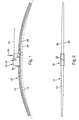
- FIG. 1 shows a side view of a Wischblatts
- Figure 2 is a plan view of the wiper blade
- Figure 3 the central portion of the Wiper blade according to Figure 1 belonging support element in view, shown enlarged
- Figure 4 is a plan view of the Arrangement according to FIG. 3, partially cut
- FIG. 5 a section through the arrangement of Figure 3, along the Line V-V
- Figure 6 a designated in Figure 4 with VI Detail
- Figure 7 is a section through a closed mold with inlaid Retaining rail before filling with plastic, for molding the Connecting device to the support rail.
- a wiper blade 10 shown in FIGS. 1 and 2 has an elongated, resilient retaining rail 12, on the bottom of which is an elongated, rubber-elastic Wiper strip 14 is attached longitudinal axis parallel.
- a connection device 16 At the Top of a spring-elastic material made retaining rail 12 is in the middle section arranged a connection device 16, with the help of the Wiper blade hinged with a powered wiper arm 18 can be releasably connected.
- the wiper arm is with his a, not shown end to a Car body guided.
- free end 20 of the wiper arm 18 is a counter-connection means serving hook formed, which a to Connecting device 16 of the wiper blade belonging Hinge pin 22 engages around ( Figure 1).
- the fuse between the wiper arm 18 and the wiper blade 10 is not by shown in detail, known per se, as an adapter trained securing means taken over.
- the wiper arm 18 and thus also the wiper blade are in the direction of the arrow 24 charged to be wiped disc whose wiping Surface in Figure 1 by a dashed line 26th is indicated. Since the dotted line 26 the is to represent the strongest curvature of the disk surface, it is clear that the curvature of his two Ends on the discs adjacent wiper blade is stronger as the maximum disc curvature. Under the contact pressure (Arrow 24) sets the wiper blade with its wiper lip 28th over its entire length on the disk surface 26 at.
- the retaining rail 12 forms together with the connecting device 16 arranged on it a support member 30 for the wiper strip 14, which via his connection device 16 with the wiper arm 18 to connect is.
- the Retaining rail 12 as a band-shaped, elongated component formed, which consists of a resilient material consists.
- the retaining rail 12 th a band surface 32, which from the surface 26 of facing away wiping disc.
- the other band surface, which faces the disk surface 26 is connected to the Reference number 34 provided.
- the retaining rail 12 has two opposite each other, in the longitudinal direction of the Retaining rail 12 extending side edges 36 and 38.
- the Support member 16 has a substantially U-shaped Cross-section.
- U-base 40 It thus has a U-base 40 and two Spaced apart, attached to the U-base U-legs 42 and 44 on.
- FIGS. 2, 4 and 5 show, hold the two U-legs 42 and 44, the hinge pin 22nd
- Each of the two U-legs 42 and 44 is with a claw-like projection 46 and 48 provided, each at the outside of the U-base 40 is arranged and the two Longitudinal side edges 36, 38 of the support rail 12 surrounds, that they on the disk facing the belt surface 34 of the Holding rail 12 abut.
- the claw-like projections 46 and 48 extend over the entire length of the connecting device 16.
- shoulders can according to Figure 4 be formed in that the retaining rail in which of the claw-like projections 46 and 48 covered area with Breakthroughs 50 is provided, whose walls are the shoulders form ( Figure 4).
- Another way to form the Shoulders can be characterized by the arrangement of open-edged Recesses 52 or by the arrangement of hook-like Formations 54 can be achieved. Both the recesses as also the formations 54 are shown in FIG. at the Anformung of the connecting device 16 to the support rail in the manner already described above, the liquid Plastic in the openings 50 and in the open-edge Recesses 52 and in the hook-like formations 54th pressed where he hardens and shoulders working together counter-shoulders.
- the required mold has according to the shown schematic representation of two mold halves 101 and 102nd on, which abut against each other at a parting line 104.
- a corresponding device clamped is the form 101, 102 openable, in which the two mold halves 101 and 102 according to the double arrow 106 are moved relative to each other.
- one of the two mold halves 102 has a Fill opening 108.
- the mold 101, 102 is a Discharge space 110 incorporated, which on the shape of the Connection device 16 ( Figures 3 to 5) is tuned.
- the Filling opening 108 opens into the pouring 110th
- the manufacturing process is as follows: The casting mold 101 and 102 is moved by moving in opposite directions (double arrow 106) of the mold halves 101 and 102. After that, the Retaining rail 12 inserted into the mold half 102. After this Closing the mold 101, 102 - in which the mold halves 101 and 102 are moved against the double arrow 106 as long as until the mold halves 101 and 102 at the parting line 104th abut each other - is the support rail 12 in the Mold half 102 fixed in its prescribed position. Now is heated by the filling opening 108 and thus flowable plastic in the direction of arrow 112 in the Pouring space 110 introduced.
- the form 101, 102 After its filling and one corresponding cooling of the plastic may be the form 101, 102 opened again and the finished support member 30 removed become. It should be noted that the design of the Form 101, 102 only the basic structure of a should show such casting or injection mold. casting technology Concerns - such as the releasability of the support element 30 - have been disregarded.
Landscapes
- Engineering & Computer Science (AREA)
- Mechanical Engineering (AREA)
- Injection Moulding Of Plastics Or The Like (AREA)
- Connection Of Plates (AREA)
- Body Structure For Vehicles (AREA)
Description
Claims (9)
- Wischblatt (10) für Scheiben von Kraftfahrzeugen mit einer an der zu wischenden Scheibe (26) anlegbaren, langgestreckten, gummielastischen Wischleiste (14), die im wesentlichen längsachsenparallel an einem eine bandartig langgestreckte, federelastische Halteschiene (12) und eine an diesem angeordnete Anschlußvorrichtung (16) aufweisenden Tragelement (30) gehalten ist, wobei die Anschlußvorrichtung (16) an der von der Scheibe (26) abgewandten Bandfläche am Mittelabschnitt der Halteschiene (12) angeordnet ist und zum Anschließen des Wischblatts (10) an einem zur Scheibe belastbaren, angetriebenen Wischerarm (18) dient, dadurch gekennzeichnet, daß die Anschlußvorrichtung (16) aus einem Kunststoff gefertigt direkt und ortsfest an die vorgefertigte Halteschiene (12) angeformt ist.
- Wischblatt nach Anspruch 1, dadurch gekennzeichnet, daß die Anschlußvorrichtung mit krallenartigen Ansätzen (46, 48) versehen ist, welche die beiden Seiten-Längskanten (36, 38) der Halteschiene (12) zumindest abschnittweise umgreifen und an der der Scheibe zugewandten Bandfläche (34) der Halteschiene (12) anliegen.
- Wischblatt nach einem der Ansprüche 1 oder 2, dadurch gekennzeichnet, daß die Halteschiene (12) mit Schultern versehen ist, denen Gegenschultern der Anschlußvorrichtung (16) zugeordnet sind.
- Wischblatt nach Anspruch 3, dadurch gekennzeichnet, daß die Schultern der Halteschiene an Durchbrüchen (50) ausgebildet sind.
- Wischblatt nach Anspruch 3, dadurch gekennzeichnet, daß die Schultern der Halteschiene an randoffenen Ausnehmungen (52) ausgebildet sind.
- Wischblatt nach Anspruch 3, dadurch gekennzeichnet, daß die Schultern der Halteschiene an hakenartigen Ausformungen (54) ausgebildet sind.
- Wischblatt nach einem der Ansprüche 1 bis 6, dadurch gekennzeichnet, daß die Halteschiene (12) an wenigstens einer ihrer der Anschlußvorrichtung (16) zugewandten Oberflächen mit Aufrauhungen (56) versehen ist.
- Wischblatt nach einem der Ansprüche 1 bis 7, dadurch gekennzeichnet, daß die Halteschiene aus einem Metall gefertigt ist.
- Verfahren zum Befestigen einer aus Kunststoff bestehenden Anschlußvorrichtung (16) für einen Wischerarm (18) an einer zu einem Tragelement (30) eines Wischblatts (10) zum Reinigen von Scheiben von Kraftfahrzeugen gemäß einem der Ansprüche 1 bis 8 gehörenden Halteschiene (12), dadurch gekennzeichnet, daß die vorgefertigte Halteschiene in eine Form (102, 104) eingebracht wird, die nach dem Schließen mit aushärtbarem Kunststoff gefüllt wird, so daß nach dem Öffnen der Form das fertige Tragelement (30) entnommen werden kann.
Applications Claiming Priority (3)
| Application Number | Priority Date | Filing Date | Title |
|---|---|---|---|
| DE19856279 | 1998-12-07 | ||
| DE19856279A DE19856279A1 (de) | 1998-12-07 | 1998-12-07 | Wischblatt für Scheiben von Kraftfahrzeugen |
| PCT/DE1999/002369 WO2000034089A1 (de) | 1998-12-07 | 1999-07-31 | Wischblatt für scheiben von kraftfahrzeugen |
Publications (2)
| Publication Number | Publication Date |
|---|---|
| EP1053144A1 EP1053144A1 (de) | 2000-11-22 |
| EP1053144B1 true EP1053144B1 (de) | 2005-07-27 |
Family
ID=7890171
Family Applications (1)
| Application Number | Title | Priority Date | Filing Date |
|---|---|---|---|
| EP99950486A Expired - Lifetime EP1053144B1 (de) | 1998-12-07 | 1999-07-31 | Wischblatt für scheiben von kraftfahrzeugen |
Country Status (7)
| Country | Link |
|---|---|
| US (1) | US6427282B1 (de) |
| EP (1) | EP1053144B1 (de) |
| JP (1) | JP4399117B2 (de) |
| KR (1) | KR100622839B1 (de) |
| DE (2) | DE19856279A1 (de) |
| ES (1) | ES2244219T3 (de) |
| WO (1) | WO2000034089A1 (de) |
Cited By (1)
| Publication number | Priority date | Publication date | Assignee | Title |
|---|---|---|---|---|
| DE102010029107A1 (de) | 2010-05-19 | 2011-11-24 | Robert Bosch Gmbh | Wischblatt für einen Scheibenwischer |
Families Citing this family (35)
| Publication number | Priority date | Publication date | Assignee | Title |
|---|---|---|---|---|
| DE102004019157A1 (de) * | 2004-04-21 | 2005-11-10 | Robert Bosch Gmbh | Wischblatt |
| US20060207050A1 (en) * | 2004-07-30 | 2006-09-21 | Subramaniam Shanmugham | Windshield wiper structure |
| US7350259B2 (en) | 2005-07-28 | 2008-04-01 | Tenneco Automotive Operating Company Inc. | Relative axial translation prevention system for wiper blade assemblies |
| KR100718335B1 (ko) * | 2006-05-11 | 2007-05-16 | 김시용 | 개폐레버를 구비하는 와이퍼블레이드 |
| US8122560B2 (en) * | 2006-08-04 | 2012-02-28 | Dongguan Hongyi Wiper Co., Ltd. | Windshield wiper bridge base assembly |
| US20080028564A1 (en) * | 2006-08-04 | 2008-02-07 | Shu-Lan Ku | Wiper blade support structure |
| DE102007040504A1 (de) * | 2007-08-28 | 2009-03-05 | Robert Bosch Gmbh | Wischanlage mit einem Wischantrieb zum Antrieb eines Wischgestänges |
| US20090151111A1 (en) * | 2007-12-18 | 2009-06-18 | Chi-Hung Chang | Windshield wiper steel bar structure |
| CN101857009B (zh) * | 2009-04-13 | 2012-01-04 | 黄世贤 | 非支架式雨刷之构造 |
| KR101098004B1 (ko) | 2009-08-26 | 2011-12-22 | 주식회사 캐프 | 차량 와이퍼용 멀티 어댑터 |
| FR2957876B1 (fr) * | 2010-03-29 | 2012-12-07 | Valeo Systemes Dessuyage | Balai d'essuie-glace de type balai plat |
| US8495787B2 (en) | 2010-08-03 | 2013-07-30 | Rally Manufacturing, Inc. | Windshield wiper |
| USD706200S1 (en) | 2010-09-22 | 2014-06-03 | Pylon Manufacturing Corporation | Windshield wiper cover |
| US9174609B2 (en) | 2011-04-21 | 2015-11-03 | Pylon Manufacturing Corp. | Wiper blade with cover |
| US9457768B2 (en) | 2011-04-21 | 2016-10-04 | Pylon Manufacturing Corp. | Vortex damping wiper blade |
| CA2843527C (en) | 2011-07-28 | 2018-11-27 | Pylon Manufacturing Corp. | Windshield wiper adapter, connector and assembly |
| WO2013019645A1 (en) | 2011-07-29 | 2013-02-07 | Pylon Manufacturing Corp. | Windshield wiper connector |
| US8806700B2 (en) | 2011-07-29 | 2014-08-19 | Pylon Manufacturing Corporation | Wiper blade connector |
| US9108595B2 (en) | 2011-07-29 | 2015-08-18 | Pylon Manufacturing Corporation | Windshield wiper connector |
| US10723322B2 (en) | 2012-02-24 | 2020-07-28 | Pylon Manufacturing Corp. | Wiper blade with cover |
| US20130219649A1 (en) | 2012-02-24 | 2013-08-29 | Pylon Manufacturing Corp. | Wiper blade |
| MX385411B (es) | 2012-02-24 | 2025-03-18 | Pylon Mfg Corp | Escobilla limpiaparabrisas. |
| US10829092B2 (en) | 2012-09-24 | 2020-11-10 | Pylon Manufacturing Corp. | Wiper blade with modular mounting base |
| US10166951B2 (en) | 2013-03-15 | 2019-01-01 | Pylon Manufacturing Corp. | Windshield wiper connector |
| KR101474838B1 (ko) | 2013-07-01 | 2014-12-22 | 주식회사 캐프 | 와이퍼 블레이드 조립체 |
| US9505380B2 (en) | 2014-03-07 | 2016-11-29 | Pylon Manufacturing Corp. | Windshield wiper connector and assembly |
| US20150360649A1 (en) * | 2014-06-16 | 2015-12-17 | Richard Dean Neff | Windshield clearing and cleaning apparatus for motor vehicles with performance improving applications |
| USD787308S1 (en) | 2014-10-03 | 2017-05-23 | Pylon Manufacturing Corp. | Wiper blade package |
| USD777079S1 (en) | 2014-10-03 | 2017-01-24 | Pylon Manufacturing Corp. | Wiper blade frame |
| US10363905B2 (en) | 2015-10-26 | 2019-07-30 | Pylon Manufacturing Corp. | Wiper blade |
| CN109311452A (zh) | 2016-05-19 | 2019-02-05 | 电缆塔制造有限公司 | 挡风玻璃雨刮器连接器 |
| EP3458315B1 (de) | 2016-05-19 | 2021-09-08 | Pylon Manufacturing Corp. | Scheibenwischerblatt |
| AU2017268008A1 (en) | 2016-05-19 | 2018-11-22 | Pylon Manufacturing Corp. | Windshield wiper connector |
| US11040705B2 (en) | 2016-05-19 | 2021-06-22 | Pylon Manufacturing Corp. | Windshield wiper connector |
| CN109311450A (zh) | 2016-05-19 | 2019-02-05 | 电缆塔制造有限公司 | 挡风玻璃雨刮器连接器 |
Family Cites Families (11)
| Publication number | Priority date | Publication date | Assignee | Title |
|---|---|---|---|---|
| US3390416A (en) * | 1946-06-15 | 1968-07-02 | Trico Products Corp | Windshield wiper |
| US3132367A (en) * | 1959-04-24 | 1964-05-12 | Ralph H Wise | Windshield wiper |
| DE1247161B (de) | 1962-05-21 | 1967-08-10 | Walter D Appel | Scheibenwischer, insbesondere fuer Kraftfahrzeuge |
| US3317945A (en) | 1965-09-17 | 1967-05-09 | Hastings Mfg Co | Molded windshield wiper blade |
| GB1429820A (en) * | 1973-12-10 | 1976-03-31 | Trico Folberth Ltd | Windscreen wiper blades |
| GB1513895A (en) * | 1974-08-22 | 1978-06-14 | Rau Swf Autozubehoer | Wiper blade for wiper installations in vehicles |
| IT1032660B (it) | 1975-04-11 | 1979-06-20 | Arman Sas Di Dario Arman Ec | Supporto lamellare per spazzole tergenti negli impianti tergivetro abordo di autoveicoli in genere |
| GB1565955A (en) * | 1976-03-31 | 1980-04-23 | Trico Folberth Ltd | Wipers primarily for vehicle headlamps |
| IT1091440B (it) * | 1977-10-13 | 1985-07-06 | Aguiari Ofer | Tergicristallo per autoveicoli |
| DE19645170A1 (de) * | 1996-11-02 | 1998-05-07 | Bosch Gmbh Robert | Wischblatt für Scheiben von Kraftfahrzeugen |
| DE19729865A1 (de) * | 1997-07-11 | 1999-01-14 | Bosch Gmbh Robert | Wischvorrichtung für Windschutzscheiben von Kraftfahrzeugen |
-
1998
- 1998-12-07 DE DE19856279A patent/DE19856279A1/de not_active Withdrawn
-
1999
- 1999-07-31 EP EP99950486A patent/EP1053144B1/de not_active Expired - Lifetime
- 1999-07-31 ES ES99950486T patent/ES2244219T3/es not_active Expired - Lifetime
- 1999-07-31 DE DE59912333T patent/DE59912333D1/de not_active Expired - Lifetime
- 1999-07-31 KR KR1020007008527A patent/KR100622839B1/ko not_active Expired - Fee Related
- 1999-07-31 WO PCT/DE1999/002369 patent/WO2000034089A1/de not_active Ceased
- 1999-07-31 US US09/601,746 patent/US6427282B1/en not_active Expired - Lifetime
- 1999-07-31 JP JP2000586557A patent/JP4399117B2/ja not_active Expired - Fee Related
Cited By (2)
| Publication number | Priority date | Publication date | Assignee | Title |
|---|---|---|---|---|
| DE102010029107A1 (de) | 2010-05-19 | 2011-11-24 | Robert Bosch Gmbh | Wischblatt für einen Scheibenwischer |
| WO2011144400A1 (de) | 2010-05-19 | 2011-11-24 | Robert Bosch Gmbh | Wischblatt für einen scheibenwischer |
Also Published As
| Publication number | Publication date |
|---|---|
| WO2000034089A1 (de) | 2000-06-15 |
| KR20010040655A (ko) | 2001-05-15 |
| EP1053144A1 (de) | 2000-11-22 |
| JP4399117B2 (ja) | 2010-01-13 |
| US6427282B1 (en) | 2002-08-06 |
| DE19856279A1 (de) | 2000-06-08 |
| JP2002531324A (ja) | 2002-09-24 |
| ES2244219T3 (es) | 2005-12-01 |
| DE59912333D1 (de) | 2005-09-01 |
| KR100622839B1 (ko) | 2006-09-12 |
Similar Documents
| Publication | Publication Date | Title |
|---|---|---|
| EP1053144B1 (de) | Wischblatt für scheiben von kraftfahrzeugen | |
| EP1037779B1 (de) | Vorrichtung zum verbinden eines wischblatts für scheiben von kraftfahrzeugen mit einem wischerarm | |
| EP1056628B1 (de) | Vorrichtung zum gelenkigen verbinden eines wischblatts für scheiben von kraftfahrzeugen mit einem wischerarm und verfahren zum herstellen dieser verbindung | |
| EP1053143B1 (de) | Vorrichtung zum gelenkigen verbinden eines wischblatts für scheiben von kraftfahrzeugen mit einem wischerarm | |
| EP0915785B1 (de) | Wischblatt für scheiben von kraftfahrzeugen | |
| EP0923469B1 (de) | Wischblatt für scheiben von kraftfahrzeugen | |
| EP1037778A1 (de) | Wischblatt für scheiben von kraftfahrzeugen | |
| DE19718490A1 (de) | Wischblatt für Scheiben von Kraftfahrzeugen | |
| EP1547884A1 (de) | Wischblatt zum Reinigen von Scheiben insbesondere von Kraftfahrzeugen | |
| EP0936983A1 (de) | Tragelement für eine zu einem wischblatt für scheiben von kraftfahrzeugen gehörenden wischleiste und verfahren zu dessen herstellung | |
| DE29918961U1 (de) | Wischvorrichtung für Scheiben von Kraftfahrzeugen | |
| DE19838883A1 (de) | Vorrichtung zum Verbinden eines Wischblatts mit einem Wischerarm | |
| EP0966373A1 (de) | Wischblatt zum reinigen von scheiben von kraftfahrzeugen | |
| WO1995029827A1 (de) | Wischarm, insbesondere für kraftfahrzeuge | |
| EP2102043B1 (de) | Wischblatt | |
| WO1998015438A1 (de) | Wischblatt für scheiben von kraftfahrzeugen | |
| WO2001051324A1 (de) | Wischblatt | |
| WO2005002934A1 (de) | Verbindung zwischen einem wischblatt und einem wischarm einer wischvorrichtung für scheiben an fahrzeugen, sowie wischvorrichtung mit einer solchen verbindung | |
| EP2214936B1 (de) | Wischblatt | |
| DE20321703U1 (de) | Wischhebel mit einem Wischerarm und einem an diesem angelenkten Wischblatt | |
| WO2016020143A1 (de) | Abschliessbarer für finray-wischer | |
| DE19861483B4 (de) | Wischblatt zum Reinigen von Scheiben von Kraftfahrzeugen | |
| DE102013203686A1 (de) | Wischblatt zum Reinigen von Scheiben insbesondere von Kraftfahrzeugen | |
| DE102006034705A1 (de) | Verfahren zum Herstellen eines Wischarmes sowie Wischarm |
Legal Events
| Date | Code | Title | Description |
|---|---|---|---|
| PUAI | Public reference made under article 153(3) epc to a published international application that has entered the european phase |
Free format text: ORIGINAL CODE: 0009012 |
|
| AK | Designated contracting states |
Kind code of ref document: A1 Designated state(s): AT BE CH CY DE DK ES FI FR GB GR IE IT LI LU MC NL PT SE |
|
| 17P | Request for examination filed |
Effective date: 20001215 |
|
| 17Q | First examination report despatched |
Effective date: 20040216 |
|
| RBV | Designated contracting states (corrected) |
Designated state(s): DE ES FR GB IT |
|
| GRAP | Despatch of communication of intention to grant a patent |
Free format text: ORIGINAL CODE: EPIDOSNIGR1 |
|
| GRAS | Grant fee paid |
Free format text: ORIGINAL CODE: EPIDOSNIGR3 |
|
| GRAA | (expected) grant |
Free format text: ORIGINAL CODE: 0009210 |
|
| AK | Designated contracting states |
Kind code of ref document: B1 Designated state(s): DE ES FR GB IT |
|
| REG | Reference to a national code |
Ref country code: GB Ref legal event code: FG4D Free format text: NOT ENGLISH |
|
| REF | Corresponds to: |
Ref document number: 59912333 Country of ref document: DE Date of ref document: 20050901 Kind code of ref document: P |
|
| REG | Reference to a national code |
Ref country code: ES Ref legal event code: FG2A Ref document number: 2244219 Country of ref document: ES Kind code of ref document: T3 |
|
| GBT | Gb: translation of ep patent filed (gb section 77(6)(a)/1977) |
Effective date: 20051111 |
|
| ET | Fr: translation filed | ||
| PLBE | No opposition filed within time limit |
Free format text: ORIGINAL CODE: 0009261 |
|
| STAA | Information on the status of an ep patent application or granted ep patent |
Free format text: STATUS: NO OPPOSITION FILED WITHIN TIME LIMIT |
|
| 26N | No opposition filed |
Effective date: 20060428 |
|
| REG | Reference to a national code |
Ref country code: FR Ref legal event code: PLFP Year of fee payment: 18 |
|
| PGFP | Annual fee paid to national office [announced via postgrant information from national office to epo] |
Ref country code: IT Payment date: 20160721 Year of fee payment: 18 Ref country code: GB Payment date: 20160722 Year of fee payment: 18 |
|
| PGFP | Annual fee paid to national office [announced via postgrant information from national office to epo] |
Ref country code: FR Payment date: 20160722 Year of fee payment: 18 |
|
| PGFP | Annual fee paid to national office [announced via postgrant information from national office to epo] |
Ref country code: ES Payment date: 20160722 Year of fee payment: 18 |
|
| PGFP | Annual fee paid to national office [announced via postgrant information from national office to epo] |
Ref country code: DE Payment date: 20170927 Year of fee payment: 19 |
|
| GBPC | Gb: european patent ceased through non-payment of renewal fee |
Effective date: 20170731 |
|
| REG | Reference to a national code |
Ref country code: FR Ref legal event code: ST Effective date: 20180330 |
|
| PG25 | Lapsed in a contracting state [announced via postgrant information from national office to epo] |
Ref country code: GB Free format text: LAPSE BECAUSE OF NON-PAYMENT OF DUE FEES Effective date: 20170731 |
|
| PG25 | Lapsed in a contracting state [announced via postgrant information from national office to epo] |
Ref country code: FR Free format text: LAPSE BECAUSE OF NON-PAYMENT OF DUE FEES Effective date: 20170731 |
|
| PG25 | Lapsed in a contracting state [announced via postgrant information from national office to epo] |
Ref country code: IT Free format text: LAPSE BECAUSE OF NON-PAYMENT OF DUE FEES Effective date: 20170731 |
|
| REG | Reference to a national code |
Ref country code: ES Ref legal event code: FD2A Effective date: 20181029 |
|
| REG | Reference to a national code |
Ref country code: DE Ref legal event code: R119 Ref document number: 59912333 Country of ref document: DE |
|
| PG25 | Lapsed in a contracting state [announced via postgrant information from national office to epo] |
Ref country code: ES Free format text: LAPSE BECAUSE OF NON-PAYMENT OF DUE FEES Effective date: 20170801 |
|
| PG25 | Lapsed in a contracting state [announced via postgrant information from national office to epo] |
Ref country code: DE Free format text: LAPSE BECAUSE OF NON-PAYMENT OF DUE FEES Effective date: 20190201 |