EP1053410B1 - Luftfedervorrichtung - Google Patents
Luftfedervorrichtung Download PDFInfo
- Publication number
- EP1053410B1 EP1053410B1 EP99906646A EP99906646A EP1053410B1 EP 1053410 B1 EP1053410 B1 EP 1053410B1 EP 99906646 A EP99906646 A EP 99906646A EP 99906646 A EP99906646 A EP 99906646A EP 1053410 B1 EP1053410 B1 EP 1053410B1
- Authority
- EP
- European Patent Office
- Prior art keywords
- piston rod
- piston
- guide
- gas spring
- spring device
- Prior art date
- Legal status (The legal status is an assumption and is not a legal conclusion. Google has not performed a legal analysis and makes no representation as to the accuracy of the status listed.)
- Expired - Lifetime
Links
- 239000012530 fluid Substances 0.000 claims description 8
- 230000000712 assembly Effects 0.000 description 2
- 238000000429 assembly Methods 0.000 description 2
- 230000000007 visual effect Effects 0.000 description 2
- 238000013459 approach Methods 0.000 description 1
- 230000000694 effects Effects 0.000 description 1
- 238000007373 indentation Methods 0.000 description 1
Images


Classifications
-
- F—MECHANICAL ENGINEERING; LIGHTING; HEATING; WEAPONS; BLASTING
- F16—ENGINEERING ELEMENTS AND UNITS; GENERAL MEASURES FOR PRODUCING AND MAINTAINING EFFECTIVE FUNCTIONING OF MACHINES OR INSTALLATIONS; THERMAL INSULATION IN GENERAL
- F16F—SPRINGS; SHOCK-ABSORBERS; MEANS FOR DAMPING VIBRATION
- F16F9/00—Springs, vibration-dampers, shock-absorbers, or similarly-constructed movement-dampers using a fluid or the equivalent as damping medium
- F16F9/02—Springs, vibration-dampers, shock-absorbers, or similarly-constructed movement-dampers using a fluid or the equivalent as damping medium using gas only or vacuum
- F16F9/0209—Telescopic
- F16F9/0281—Details
-
- F—MECHANICAL ENGINEERING; LIGHTING; HEATING; WEAPONS; BLASTING
- F16—ENGINEERING ELEMENTS AND UNITS; GENERAL MEASURES FOR PRODUCING AND MAINTAINING EFFECTIVE FUNCTIONING OF MACHINES OR INSTALLATIONS; THERMAL INSULATION IN GENERAL
- F16F—SPRINGS; SHOCK-ABSORBERS; MEANS FOR DAMPING VIBRATION
- F16F7/00—Vibration-dampers; Shock-absorbers
- F16F7/12—Vibration-dampers; Shock-absorbers using plastic deformation of members
- F16F7/123—Deformation involving a bending action, e.g. strap moving through multiple rollers, folding of members
-
- F—MECHANICAL ENGINEERING; LIGHTING; HEATING; WEAPONS; BLASTING
- F16—ENGINEERING ELEMENTS AND UNITS; GENERAL MEASURES FOR PRODUCING AND MAINTAINING EFFECTIVE FUNCTIONING OF MACHINES OR INSTALLATIONS; THERMAL INSULATION IN GENERAL
- F16F—SPRINGS; SHOCK-ABSORBERS; MEANS FOR DAMPING VIBRATION
- F16F9/00—Springs, vibration-dampers, shock-absorbers, or similarly-constructed movement-dampers using a fluid or the equivalent as damping medium
- F16F9/02—Springs, vibration-dampers, shock-absorbers, or similarly-constructed movement-dampers using a fluid or the equivalent as damping medium using gas only or vacuum
- F16F9/0209—Telescopic
- F16F9/0218—Mono-tubular units
-
- F—MECHANICAL ENGINEERING; LIGHTING; HEATING; WEAPONS; BLASTING
- F16—ENGINEERING ELEMENTS AND UNITS; GENERAL MEASURES FOR PRODUCING AND MAINTAINING EFFECTIVE FUNCTIONING OF MACHINES OR INSTALLATIONS; THERMAL INSULATION IN GENERAL
- F16F—SPRINGS; SHOCK-ABSORBERS; MEANS FOR DAMPING VIBRATION
- F16F9/00—Springs, vibration-dampers, shock-absorbers, or similarly-constructed movement-dampers using a fluid or the equivalent as damping medium
- F16F9/32—Details
- F16F9/58—Stroke limiting stops, e.g. arranged on the piston rod outside the cylinder
- F16F9/585—Stroke limiting stops, e.g. arranged on the piston rod outside the cylinder within the cylinder, in contact with working fluid
-
- F—MECHANICAL ENGINEERING; LIGHTING; HEATING; WEAPONS; BLASTING
- F16—ENGINEERING ELEMENTS AND UNITS; GENERAL MEASURES FOR PRODUCING AND MAINTAINING EFFECTIVE FUNCTIONING OF MACHINES OR INSTALLATIONS; THERMAL INSULATION IN GENERAL
- F16F—SPRINGS; SHOCK-ABSORBERS; MEANS FOR DAMPING VIBRATION
- F16F2230/00—Purpose; Design features
- F16F2230/24—Detecting or preventing malfunction, e.g. fail safe
Definitions
- This invention relates to gas spring devices, and more particularly this invention relates to a gas spring device having improved safety.
- a gas spring is normally pre-loaded with gas under high pressure, typically 60-160 bar. If the piston of the gas spring is accidentally broken away from the piston rod during use, the piston rod is free to accelerate in a piston rod guide on its way out of the gas spring.
- U.S. Patent 5,485,987 shows a gas spring where the piston rod seal is axially displaceable in order to open a normally closed radial bore through the cylinder, in order to permit escape of pressurized gas in case of the pressurized gas exceeding a predetermined pressure.
- U.S. Patent 5,454,455 shows a cylinder piston device where the piston, as it approaches the end of the cylinder, is arranged to abut against an indentation of the cylinder so as to be tilted or angled by the abutment in order to achieve a clamping effect which prevents expulsion of the piston rod and initiates a leak allowing pressurized fluid to escape.
- a further gas spring is shown in DE-A1-24 57 938 in which pressurized fluid can be evacuated through controlled breakage of the cylinder and/or the piston rod at specially designed breaking points.
- pressurized fluid can be evacuated through controlled breakage of the cylinder and/or the piston rod at specially designed breaking points.
- parts of the cylinder piston device are able to separate and become a high velocity projectile.
- DE-A1-42 16 573 shows a gas spring in which a guide is arranged to deform a piston rod seal in order to evacuate the pressurized gas from the gas spring if the pressure becomes to high.
- the purpose of the present invention is to provide a safe and effective way to reduce to zero the velocity of a piston rod which is traveling at a high velocity in a gas spring device during a failure of the gas spring device. This achieved by stopping the piston rod in a controlled manner through a stepwise reduction in its energy and velocity to keep the force on the piston to a minimum at all times during a gas spring device failure.
- a piston cylinder device having a tubular wall, an end wall at a first end of the tubular wall, and a guide at a second end of the tubular wall.
- the tubular wall, the end wall, and the guide define a pressure chamber therebetween, and a piston rod slideably extends through the guide and into the pressure chamber.
- Frangible means are provided for preventing ejection of the piston rod from the guide by breaking at a predetermined level of impact of the piston against the guide.
- the frangible means provide a controlled stoppage of the piston rod through a stepwise dissipation of its kinetic energy.
- a gas spring device including a cylinder having a tubular wall, an end wall at a first end of the tubular wall, and a guide at a second end of the tubular wall.
- the tubular wall, the end wall, and the guide form a pressure chamber therebetween.
- a piston rod and piston assembly is associated with the cylinder, with the assembly including a piston rod extending through the guide and into the pressure chamber, with the piston rod being slideable relative to the guide, and a piston is connected to the piston rod within the pressure chamber.
- a breaking zone formed on one of the assembly and the guide to dissipate the kinetic energy of the piston rod during a failure of the gas spring device.
- the gas spring device 10 includes a cylinder 12 having a tubular wall 14 with an end wall 16 closing off one end of the tubular wall.
- the opposite end of the tubular wall 14 includes an opening 18, and a piston rod guide 20 is fixedly secured within the opening 18 by a locking ring 22 so as to form a pressure chamber 24 in the cylinder 12.
- a seal 26 is disposed between the piston rod guide 20 and the interior surface of the tubular wall 14, in order to prevent fluid leakage between the exterior of the guide 20 and the interior surface of the tubular wall 14.
- the pressure chamber 24 is normally pre-loaded with gas under high pressure, typically on the order to 60-160 bar.
- the guide 20 includes a central opening 28 therethrough, and a piston rod 30 is slidingly received in the opening 28 and extends into the pressure chamber 24.
- a piston 32 is secured to the end of the piston rod 30 in the pressure chamber 24.
- a seal 31 surrounds the piston rod 30 and is disposed against the end of the guide 20 in order to prevent fluid leakage between the piston rod and the guide.
- the gas spring device 10 of the present invention is designed to stop the piston rod in a controlled manner upon a failure in the gas spring device which causes the piston rod 30 to move with high velocity in the direction of the arrow A shown in Figure 1. This is accomplished by designing the gas spring device 10 with a plurality of frangible components which are designed to break during a failure which results in uncontrolled high velocity movement of the piston rod, thereby absorbing the kinetic energy of the piston rod 30 and causing it to stop.
- the piston rod guide 20 includes a main body portion 34 which defines the opening 28, and a cylindrical skirt portion 36 extending into the pressure chamber 24 from the end of the main body portion 34.
- the skirt portion 36 is connected to the main body portion 34 at a breaking zone 38 which is designed to allow the skirt portion to break from the main body portion when a sufficient force is applied to the skirt portion by the piston 32 during an uncontrolled high velocity movement of the piston rod 30.
- the skirt portion 36 is further provided with a head portion 40 which is connected to the skirt portion by a breaking zone 42, such that the head portion can break away from the rest of the skirt portion during a failure.
- the skirt portion 36 and the head portion 40 of the skirt portion are both frangible components which are designed to break during high velocity movement of the piston rod.
- the piston 32 is further designed to break away from the piston rod 30 during a failure, thereby absorbing further energy.
- a piston rod and piston assembly is illustrated in which the piston 32 is integrally formed with the piston rod 30.
- the piston rod 30 includes an enlarged end 44 upon which the piston 32 is integrally formed.
- a breaking zone 46 is generally defined at the juncture of the piston 32 and the enlarged end 44 such that the piston 32 is able to break away from the enlarged end 44 during a failure, to thereby absorb further kinetic energy.
- the diameter of the enlarged end 44 is greater than the diameter of the opening 28, such that the piston rod 30 is prevented from ejecting from the gas spring device 10 due to interference between the enlarged end 44 and the opening 28.
- FIG. 2b A further embodiment of a piston rod and piston assembly is illustrated in Figure 2b, in which the piston 32' is not integrally formed with the piston rod 30', but is instead secured to the piston rod 30' by a lock ring 48 which is disposed in a circumferential groove in the piston rod and in a groove in the piston 32'.
- the piston 32' can be designed such that a portion thereof is broken off at a breaking zone 46', with the remainder of the piston remaining attached to the piston rod 30'.
- the remaining portion of the piston has a diameter larger than the opening 28, thus preventing ejection of the piston rod 30'.
- the remaining portion of the piston 32' thus acts similar to the enlarged end 44 of the piston rod 30.
- the entire piston 32' can be designed to break away from the piston rod 30', leaving only the retaining ring 48.
- the exterior diameter of the retaining ring 48 is larger than the diameter of the opening 28, thereby preventing ojection of the piston rod 30'.
- the piston 32,32' of the present invention is also designed as a frangible component which is designed to break during a failure, to thereby dissipate the kinetic energy of the fast moving piston rod.
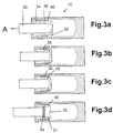
- Figures 3a-d illustrate one possible failure sequence that can occur during a failure of the gas spring device 10, utilizing the piston rod and piston assembly of Figure 2a.
- Figure 3a illustrates the device 10 in the initial stages of failure, with the piston rod 30 just starting to move at high speed to the left in the direction of the arrow A.
- the piston 32 Upon further movement of the piston rod, the piston 32 will contact the head portion 40 of the skirt portion 36, thus causing the skirt portion to break away from the main body portion 34 at breaking zone 38 as shown in Figure 3b.
- the broken away skirt portion 36 will be forced onto the main body portion and/or against the inner wall of the tubular wall 14, thereby causing the space for the seal 31 to change in form and shape and thus introducing a gas leak.
- a gas leak provides a visual indication of a failure within the gas spring device 10.
- the head portion 40 of the skirt will then break away at breaking zone 42, as shown in Figure 3c, thereby further dissipating energy.
- the head portion 40 will be forced against the seal 31 by the piston rod and piston assembly, with the seal 31 acting as a damper to dissipate further energy of the now slower moving piston rod.
- the space for the seal 31 will deform even more, and thereby introduce even further gas leakage.
- Figures 4a and 4b illustrate other possible failure sequences are illustrated in Figures 4a and 4b, in which Figure 4a illustrates the piston 32 being broken away from the piston rod 30, with no other components breaking away, and Figure 4b illustrates both the skirt portion of the guide 20 and the piston being broken.
- Figure 5a illustrates a failure sequence in which the head portion 40 is broken away, thus changing the space for the seal 31 and thereby introducing a fluid leakage.
- Figure 5b illustrates a sequence similar to Figure 5a, except that both the head portion 40 and the piston 32 are broken off.
- the breakage of the various frangible components of the gas spring device of the present invention in addition to the deformation of the seal 31 and the opening 28, achieve a controlled stoppage of the piston rod during a failure of the gas spring device, by stepwise dissipating its kinetic energy. Further, the deformation of the seal 31 allows fluid to leak from the cylinder 12, thus providing a visual indication of the occurrence of a failure.
Landscapes
- Engineering & Computer Science (AREA)
- General Engineering & Computer Science (AREA)
- Mechanical Engineering (AREA)
- Fluid-Damping Devices (AREA)
- Vehicle Body Suspensions (AREA)
- Pipe Accessories (AREA)
- Actuator (AREA)
Claims (13)
- Kolbenzylinder-Vorrichtung (10) mit:dadurch gekennzeichnet, dasseinem Zylinder (12) mit einer röhrenförmigen Wand (14), einer Endwand (16) an einem ersten Ende der röhrenförmigen Wand (14) und einem Führungselement (20) an einem zweiten Ende der röhrenförmigen Wand (14), wobei die röhrenförmige Wand (14), die Endwand (16) und das Führungselement (20) eine Druckkammer (24) dazwischen bilden, wobei ein Kolben (32) mit der Kolbenstange (30) verbunden ist und in der Druckkammer (24) angeordnet ist,einer Kolbenstange (30), die sich durch das Führungselement (20) und in die Druckkammer (24) erstreckt, wobei die Kolbenstange (30) bezüglich dem Führungselement (20) gleitbar ist;
zerbrechliche Mittel angeordnet sind, um einen Auswurf der Kolbenstange (30) von dem Führungselement (20) durch Brechen bei einer vorbestimmten Aufprallstärke des Kolben (32) gegen das Führungselement (20) zu verhindern. - Kolbenzylinder-Vorrichtung (10) gemäß Anspruch 1, bei
der das zerbrechliche Mittel einen Mantel (36) umfasst, der sich in die Druckkammer (24) von dem Führungselement (20) erstreckt. - Kolbenzylinder-Vorrichtung (10) gemäß Anspruch 2, bei
der das zerbrechliche Mittel ferner einen mit dem Mantel (36) verbundenen Kopfabschnitt (40) umfasst. - Kolbenzylinder-Vorrichtung (10) gemäß Anspruch 1, bei
der das zerbrechliche Mittel einen mit der Kolbenstange (30) verbundenen Kolben (32) umfasst. - Gasfeder-Vorrichtung (10) mit:gekennzeichnet durcheinem Zylinder (12) mit einer röhrenförmigen Wand (14), einer Endwand (16) an einem ersten Ende der röhrenförmigen Wand (14) und einem Führungselement (20) an einem zweiten Ende der röhrenförmigen Wand (14), wobei die röhrenförmige Wand (14), die Endwand (16) und das Führungselement (20) eine Druckkammer (24) dazwischen bilden;einer Kolbenstange (30) und einer dem Zylinder (12) zugeordneten Kolbenanordnung, wobei die Anordnung eine Kolbenstange (30), die sich durch das Führungselement (20) und in die Druckkammer (24) erstreckt, wobei die Kolbenstange (30) bezüglich dem Führungselement (20) gleitbar ist, und einen Kolben (32) umfasst, der mit der Kolbenstange (30) verbunden ist und in der Druckkammer (24) angeordnet ist;
eine Bruchzone, die an der Anordnung oder dem. Führungselement (20) gebildet ist, um kinetische Energie der Kolbenstange (30) zu dissipieren. - Gasfeder-Vorrichtung (10) gemäß Anspruch 5, bei der die Bruchzone an dem Führungselement (20) gebildet ist.
- Gasfeder-Vorrichtung (10) gemäß Anspruch 6, bei der das Führungselement (20) einen Mantel (36) aufweist, der sich davon in die Druckkammer (24) erstreckt, wobei der Mantel (36) mit dem Führungselement (20) an einer ersten Bruchzone (38) verbunden ist.
- Gasfeder-Vorrichtung (10) gemäß Anspruch 7, ferner mit
einem Kopfabschnitt (40) an einem freien Ende des Mantels (36), wobei der Kopfabschnitt (40) mit dem Mantel (36) an einer zweiten Bruchzone (42) verbunden ist. - Gasfeder-Vorrichtung (10) gemäß Anspruch 5, bei der die Bruchzone an der Anordnung gebildet ist.
- Gasfeder-Vorrichtung (10) gemäß Anspruch 9, bei der die Kolbenstange (30) ein vergrößertes Ende (44) aufweist, und der Kolben (32) mit dem vergrößerten Ende (44) verbunden ist.
- Gasfeder-Vorrichtung (10) gemäß Anspruch 9, bei der der Kolben (32) mit der Kolbenstange (30') durch einen Klemmring (48) verbunden ist.
- Gasfeder-Vorrichtung (10) gemäß Anspruch 5, bei der das Führungselement (20) eine zylindrische Öffnung (28) aufweist, durch die sich die Kolbenstange (30) erstreckt, wobei die Öffnung (28) einen Durchmesser aufweist, und die Kolbenstange (30) ein Ende (44) aufweist, das in der Druckkammer (24) angeordnet ist, wobei das Ende (44) einen Durchmesser aufweist, der größer als der Durchmesser der Öffnung (28) ist.
- Gasfeder-Vorrichtung (10) gemäß Anspruch 12, ferner mit einer Dichtung (31) zwischen der Kolbenstange (30) und dem Führungselement (20), um Fluid-Leckage durch die zylindrische Öffnung (28) zu verhindern, wobei die Dichtung (31) durch das Führungselement (20) oder die Anordnung zu einem Ausmaß deformierbar ist, das eine Fluid-Leckage durch die zylindrische Öffnung (28) erlaubt.
Applications Claiming Priority (3)
| Application Number | Priority Date | Filing Date | Title |
|---|---|---|---|
| US09/023,839 US6086059A (en) | 1998-02-13 | 1998-02-13 | Gas spring device |
| US23839 | 1998-02-13 | ||
| PCT/SE1999/000157 WO1999041520A1 (en) | 1998-02-13 | 1999-02-08 | Gas spring device |
Publications (2)
| Publication Number | Publication Date |
|---|---|
| EP1053410A1 EP1053410A1 (de) | 2000-11-22 |
| EP1053410B1 true EP1053410B1 (de) | 2002-07-17 |
Family
ID=21817511
Family Applications (1)
| Application Number | Title | Priority Date | Filing Date |
|---|---|---|---|
| EP99906646A Expired - Lifetime EP1053410B1 (de) | 1998-02-13 | 1999-02-08 | Luftfedervorrichtung |
Country Status (7)
| Country | Link |
|---|---|
| US (1) | US6086059A (de) |
| EP (1) | EP1053410B1 (de) |
| JP (1) | JP3899508B2 (de) |
| AT (1) | ATE220769T1 (de) |
| DE (2) | DE69902147T2 (de) |
| ES (1) | ES2177244T3 (de) |
| WO (1) | WO1999041520A1 (de) |
Cited By (1)
| Publication number | Priority date | Publication date | Assignee | Title |
|---|---|---|---|---|
| WO2017220464A1 (en) | 2016-06-22 | 2017-12-28 | Strömsholmen Ab | Piston cylinder device with protection arrangement and method of protecting a piston cylinder device against overload or failure of the piston cylinder device |
Families Citing this family (23)
| Publication number | Priority date | Publication date | Assignee | Title |
|---|---|---|---|---|
| DE10056276B4 (de) * | 2000-11-14 | 2004-12-09 | Stabilus Gmbh | Kolbenstangenführung, insbesondere für ein Gasfeder, mit einem Endanschlag |
| ES2262904T3 (es) * | 2002-01-22 | 2006-12-01 | Stabilus Gmbh | Elemento de regulacion con un cilindro. |
| FR2840041B1 (fr) * | 2002-05-23 | 2004-07-16 | Snecma Moteurs | Biellette fusible avec amortisseur et butee antiretour |
| FR2844855B1 (fr) * | 2002-09-19 | 2004-11-26 | Orflam Ind | Ressort a gaz muni d'un organe de brassage |
| FR2844854B1 (fr) * | 2002-09-19 | 2006-04-28 | Orflam Ind | Ressort a gaz depourvu de chambre de lubrification ou comportant une chambre de lubrification de volume reduit |
| US6726272B1 (en) * | 2002-10-24 | 2004-04-27 | International Truck Intellectual Property Company, Llc | Truck cab suspension system |
| US6942261B2 (en) * | 2003-08-14 | 2005-09-13 | Autoliv Asp, Inc. | Linear actuator with an internal dampening mechanism |
| US7559542B2 (en) * | 2004-08-19 | 2009-07-14 | Diebolt International, Inc. | Low impact gas spring |
| US7921973B2 (en) * | 2006-05-31 | 2011-04-12 | Techno-Sciences, Inc. | Adaptive energy absorption system for a vehicle seat |
| US7621382B2 (en) * | 2006-06-28 | 2009-11-24 | Nissan Technical Center North America, Inc. | Shock absorber |
| IT1393971B1 (it) * | 2009-04-21 | 2012-05-17 | Special Springs Srl | Molla a gas con dispositivo di sicurezza per l'eiezione controllata dello stelo pistone |
| DE102010022373B4 (de) * | 2010-05-26 | 2024-12-12 | Illinois Tool Works Inc. | Dämpfer |
| ES2405937B1 (es) * | 2011-11-29 | 2014-07-30 | Técnicas Aplicadas De Presión, S.L. | Diseño de cilindro-pistón a gas |
| ES2405850B1 (es) | 2011-11-29 | 2014-07-30 | Técnicas Aplicadas De Presión, S.L. | Diseño de cilindro-pistón a gas |
| US9046146B2 (en) * | 2012-02-14 | 2015-06-02 | Dadco, Inc. | Gas spring and gas spring components |
| DE102014224259B4 (de) * | 2014-11-27 | 2024-07-25 | Van Halteren Technologies Boxtel B.V. | Linearaktuator |
| US9840863B2 (en) | 2016-03-09 | 2017-12-12 | Honda Motor Co., Ltd. | Vehicle door strut apparatus, and methods of use and manufacture thereof |
| ITUA20161965A1 (it) * | 2016-03-24 | 2017-09-24 | Special Springs Srl | Molla a gas con dispositivo marcatore di extra-corsa |
| US10113605B2 (en) * | 2016-09-29 | 2018-10-30 | Dadco, Inc. | Overtravel relief assembly for a gas spring |
| IT201700018002A1 (it) * | 2017-02-17 | 2018-08-17 | Special Springs Srl | Struttura di molla a gas con dispositivo di sicurezza per ritorno incontrollato dello stelo-pistone |
| EP3364066B1 (de) * | 2017-02-17 | 2020-06-24 | Special Springs S.r.l. | Gaszylinderaktuator mit sicherheitsvorrichtung zur unkontrollierten rückstellung des kolbenschafts |
| USD855448S1 (en) * | 2017-06-06 | 2019-08-06 | Yajun Hu | Releasing head of gas spring |
| CN111271403A (zh) * | 2018-12-04 | 2020-06-12 | 中国科学院宁波材料技术与工程研究所 | 高强度安全型氮气弹簧 |
Family Cites Families (27)
| Publication number | Priority date | Publication date | Assignee | Title |
|---|---|---|---|---|
| US3968862A (en) * | 1974-03-20 | 1976-07-13 | Menasco Manufacturing Company | Kinetic energy absorbing value assembly |
| DE2457938C2 (de) * | 1974-12-07 | 1982-10-28 | Stabilus Gmbh, 5400 Koblenz | Sicherheitsgasfeder |
| US4003456A (en) * | 1975-10-09 | 1977-01-18 | General Electric Company | Electrical cable reeling apparatus |
| US4108423A (en) * | 1976-07-19 | 1978-08-22 | Atwood Vacuum Machine Company | Gas spring |
| US4185542A (en) * | 1978-02-27 | 1980-01-29 | Bertea Corporation | Actuator with frangible gland construction |
| US4257581A (en) * | 1979-07-25 | 1981-03-24 | Keeler Corporation | Impact absorbing strut |
| US4718647A (en) * | 1980-02-20 | 1988-01-12 | Avm, Inc. | Pneumatic counterbalance with dual force |
| US4426109A (en) * | 1981-07-20 | 1984-01-17 | Fike Metal Products Corporation | Shear type pressure relief device for hydraulic energy absorption unit |
| DE3151070C2 (de) * | 1981-12-23 | 1994-07-14 | Stabilus Gmbh | Sicherheits-Gasfeder für Motorhauben und/oder Kofferraumklappen von Kraftfahrzeugen |
| DE3419165A1 (de) * | 1984-05-23 | 1985-11-28 | Boge Gmbh, 5208 Eitorf | Pralldaempfer mit zwei ineinander schieblichen rohren |
| FR2582764B1 (fr) * | 1985-05-28 | 1989-05-19 | Socalfram | Ressort pneumatique |
| US4789192A (en) * | 1985-12-20 | 1988-12-06 | General Motors Corporation | Two-stage variable orifice energy absorber with cylinder cap having radially fixed blow out orifice |
| DE8710208U1 (de) * | 1987-07-25 | 1988-11-24 | Fritz Bauer + Söhne oHG, 8503 Altdorf | Fluidgefüllte Kolben-Zylinder-Einheit |
| US4792128A (en) * | 1988-03-08 | 1988-12-20 | Power Components, Inc. | No grow gas spring |
| DE3822322C2 (de) * | 1988-07-01 | 1996-11-14 | Fichtel & Sachs Ag | Pralldämpfer mit einer Sollbruchstelle |
| DE3901449C1 (de) * | 1989-01-19 | 1990-02-01 | Boge Ag, 5208 Eitorf, De | |
| DE3919945C2 (de) * | 1989-06-19 | 1998-04-16 | Mannesmann Sachs Ag | Pralldämpfer mit Sicherheitsentlüftung |
| US5014603A (en) * | 1989-11-02 | 1991-05-14 | Allied-Signal Inc. | Hydraulic actuator having frangible or deformable components |
| US5197718A (en) * | 1990-12-14 | 1993-03-30 | Wallis Bernard J | Self-contained gas springs interchangeable with coil springs |
| US5735371A (en) * | 1991-01-21 | 1998-04-07 | Stabilus Gmbh | Cylinder piston device |
| DE19535711C1 (de) * | 1995-09-26 | 1997-01-23 | Stabilus Gmbh | Verstellelement |
| DE4101567A1 (de) * | 1991-01-21 | 1992-07-23 | Stabilus Gmbh | Verstellelement |
| US5275387A (en) * | 1992-04-09 | 1994-01-04 | Power Components, Inc. | Gas spring |
| DE4216573C2 (de) * | 1992-05-04 | 1994-05-05 | Goetze Ag | Gasfeder |
| DE4236961A1 (de) * | 1992-11-02 | 1994-05-05 | Fichtel & Sachs Ag | Brandsicherung für einen Schwingungsdämpfer |
| DE4403127C2 (de) * | 1993-08-04 | 1998-01-22 | Mannesmann Sachs Ag | Pralldämpfer mit Deformationskörper |
| DE19514682C2 (de) * | 1995-04-20 | 1998-07-02 | Mannesmann Sachs Ag | Pralldämpfer |
-
1998
- 1998-02-13 US US09/023,839 patent/US6086059A/en not_active Expired - Lifetime
-
1999
- 1999-02-08 WO PCT/SE1999/000157 patent/WO1999041520A1/en not_active Ceased
- 1999-02-08 DE DE69902147T patent/DE69902147T2/de not_active Expired - Lifetime
- 1999-02-08 DE DE1053410T patent/DE1053410T1/de active Pending
- 1999-02-08 JP JP2000531675A patent/JP3899508B2/ja not_active Expired - Fee Related
- 1999-02-08 ES ES99906646T patent/ES2177244T3/es not_active Expired - Lifetime
- 1999-02-08 AT AT99906646T patent/ATE220769T1/de not_active IP Right Cessation
- 1999-02-08 EP EP99906646A patent/EP1053410B1/de not_active Expired - Lifetime
Cited By (1)
| Publication number | Priority date | Publication date | Assignee | Title |
|---|---|---|---|---|
| WO2017220464A1 (en) | 2016-06-22 | 2017-12-28 | Strömsholmen Ab | Piston cylinder device with protection arrangement and method of protecting a piston cylinder device against overload or failure of the piston cylinder device |
Also Published As
| Publication number | Publication date |
|---|---|
| DE69902147D1 (de) | 2002-08-22 |
| US6086059A (en) | 2000-07-11 |
| ATE220769T1 (de) | 2002-08-15 |
| WO1999041520A1 (en) | 1999-08-19 |
| JP3899508B2 (ja) | 2007-03-28 |
| JP2002503791A (ja) | 2002-02-05 |
| EP1053410A1 (de) | 2000-11-22 |
| DE69902147T2 (de) | 2003-04-03 |
| DE1053410T1 (de) | 2001-09-20 |
| ES2177244T3 (es) | 2002-12-01 |
Similar Documents
| Publication | Publication Date | Title |
|---|---|---|
| EP1053410B1 (de) | Luftfedervorrichtung | |
| EP0892648B1 (de) | Federgetriebene verabreichungsvorrichtung für medizinische zwecke | |
| US4424737A (en) | Stroke cushioning apparatus for hydraulic cylinders | |
| US11378105B2 (en) | Gas cylinder actuator with safety device for uncontrolled return of the piston-stem | |
| US6027105A (en) | Impact damper | |
| US6840153B2 (en) | Fire protection in a piston-cylinder unit | |
| US5454455A (en) | Cylinder piston device | |
| KR20220139240A (ko) | 가스 스프링 | |
| US4291788A (en) | Cylinder head | |
| JPH10181528A (ja) | ベルト締め装置 | |
| GB2312659A (en) | Buffers | |
| US11274723B2 (en) | Closure package, vibration damper, and use of a seal holder | |
| US11970132B2 (en) | Pyrotechnic tightening device for a safety belt of a safety belt unit having a force-limiting unit | |
| KR970075353A (ko) | 리니어 압축기의 실린더 충격흡수장치 | |
| WO1993012361A1 (en) | A buffer | |
| EP3884181A1 (de) | Verbesserungen bei dämpfern | |
| US12560216B2 (en) | Gas pressure spring with overpressure protection, method for manufacturing the gas pressure spring | |
| CN120798920A (zh) | 一种气动解锁装置 | |
| KR101992129B1 (ko) | 완충기 | |
| GB1587297A (en) | Hydraulically damped buffer for railway vehicles | |
| KR960005525B1 (ko) | 특수 밀폐부재를 갖는 차량용 충격흡수장치 | |
| IT201700018002A1 (it) | Struttura di molla a gas con dispositivo di sicurezza per ritorno incontrollato dello stelo-pistone |
Legal Events
| Date | Code | Title | Description |
|---|---|---|---|
| PUAI | Public reference made under article 153(3) epc to a published international application that has entered the european phase |
Free format text: ORIGINAL CODE: 0009012 |
|
| 17P | Request for examination filed |
Effective date: 20000819 |
|
| AK | Designated contracting states |
Kind code of ref document: A1 Designated state(s): AT BE DE ES FR GB IT NL PT SE |
|
| DET | De: translation of patent claims | ||
| GRAG | Despatch of communication of intention to grant |
Free format text: ORIGINAL CODE: EPIDOS AGRA |
|
| 17Q | First examination report despatched |
Effective date: 20011128 |
|
| GRAG | Despatch of communication of intention to grant |
Free format text: ORIGINAL CODE: EPIDOS AGRA |
|
| GRAH | Despatch of communication of intention to grant a patent |
Free format text: ORIGINAL CODE: EPIDOS IGRA |
|
| GRAH | Despatch of communication of intention to grant a patent |
Free format text: ORIGINAL CODE: EPIDOS IGRA |
|
| GRAA | (expected) grant |
Free format text: ORIGINAL CODE: 0009210 |
|
| AK | Designated contracting states |
Kind code of ref document: B1 Designated state(s): AT BE DE ES FR GB IT NL PT SE |
|
| PG25 | Lapsed in a contracting state [announced via postgrant information from national office to epo] |
Ref country code: NL Free format text: LAPSE BECAUSE OF FAILURE TO SUBMIT A TRANSLATION OF THE DESCRIPTION OR TO PAY THE FEE WITHIN THE PRESCRIBED TIME-LIMIT Effective date: 20020717 Ref country code: AT Free format text: LAPSE BECAUSE OF FAILURE TO SUBMIT A TRANSLATION OF THE DESCRIPTION OR TO PAY THE FEE WITHIN THE PRESCRIBED TIME-LIMIT Effective date: 20020717 |
|
| REF | Corresponds to: |
Ref document number: 220769 Country of ref document: AT Date of ref document: 20020815 Kind code of ref document: T |
|
| REG | Reference to a national code |
Ref country code: GB Ref legal event code: FG4D |
|
| REF | Corresponds to: |
Ref document number: 69902147 Country of ref document: DE Date of ref document: 20020822 |
|
| PG25 | Lapsed in a contracting state [announced via postgrant information from national office to epo] |
Ref country code: PT Free format text: LAPSE BECAUSE OF FAILURE TO SUBMIT A TRANSLATION OF THE DESCRIPTION OR TO PAY THE FEE WITHIN THE PRESCRIBED TIME-LIMIT Effective date: 20021017 |
|
| ET | Fr: translation filed | ||
| REG | Reference to a national code |
Ref country code: ES Ref legal event code: FG2A Ref document number: 2177244 Country of ref document: ES Kind code of ref document: T3 |
|
| NLV1 | Nl: lapsed or annulled due to failure to fulfill the requirements of art. 29p and 29m of the patents act | ||
| PLBE | No opposition filed within time limit |
Free format text: ORIGINAL CODE: 0009261 |
|
| STAA | Information on the status of an ep patent application or granted ep patent |
Free format text: STATUS: NO OPPOSITION FILED WITHIN TIME LIMIT |
|
| 26N | No opposition filed |
Effective date: 20030422 |
|
| REG | Reference to a national code |
Ref country code: DE Ref legal event code: R082 Ref document number: 69902147 Country of ref document: DE Representative=s name: MAI DOERR BESIER EUROPEAN PATENT ATTORNEYS - E, DE Ref country code: DE Ref legal event code: R082 Ref document number: 69902147 Country of ref document: DE Representative=s name: MAI DOERR BESIER PATENTANWAELTE, DE |
|
| REG | Reference to a national code |
Ref country code: FR Ref legal event code: PLFP Year of fee payment: 17 |
|
| REG | Reference to a national code |
Ref country code: FR Ref legal event code: PLFP Year of fee payment: 18 |
|
| REG | Reference to a national code |
Ref country code: FR Ref legal event code: PLFP Year of fee payment: 19 |
|
| REG | Reference to a national code |
Ref country code: DE Ref legal event code: R039 Ref document number: 69902147 Country of ref document: DE Ref country code: DE Ref legal event code: R008 Ref document number: 69902147 Country of ref document: DE |
|
| REG | Reference to a national code |
Ref country code: FR Ref legal event code: PLFP Year of fee payment: 20 |
|
| PGFP | Annual fee paid to national office [announced via postgrant information from national office to epo] |
Ref country code: ES Payment date: 20180305 Year of fee payment: 20 Ref country code: GB Payment date: 20180126 Year of fee payment: 20 Ref country code: DE Payment date: 20180123 Year of fee payment: 20 |
|
| PGFP | Annual fee paid to national office [announced via postgrant information from national office to epo] |
Ref country code: FR Payment date: 20180119 Year of fee payment: 20 Ref country code: IT Payment date: 20180123 Year of fee payment: 20 Ref country code: SE Payment date: 20180118 Year of fee payment: 20 Ref country code: BE Payment date: 20180119 Year of fee payment: 20 |
|
| REG | Reference to a national code |
Ref country code: DE Ref legal event code: R071 Ref document number: 69902147 Country of ref document: DE |
|
| REG | Reference to a national code |
Ref country code: GB Ref legal event code: PE20 Expiry date: 20190207 |
|
| REG | Reference to a national code |
Ref country code: BE Ref legal event code: MK Effective date: 20190208 |
|
| REG | Reference to a national code |
Ref country code: DE Ref legal event code: R040 Ref document number: 69902147 Country of ref document: DE |
|
| REG | Reference to a national code |
Ref country code: SE Ref legal event code: EUG |
|
| PG25 | Lapsed in a contracting state [announced via postgrant information from national office to epo] |
Ref country code: GB Free format text: LAPSE BECAUSE OF EXPIRATION OF PROTECTION Effective date: 20190207 |
|
| REG | Reference to a national code |
Ref country code: ES Ref legal event code: FD2A Effective date: 20211229 |
|
| PG25 | Lapsed in a contracting state [announced via postgrant information from national office to epo] |
Ref country code: ES Free format text: LAPSE BECAUSE OF EXPIRATION OF PROTECTION Effective date: 20190209 |