EP1053553B1 - Fernauslöser für eine schaltvorrichtung - Google Patents
Fernauslöser für eine schaltvorrichtung Download PDFInfo
- Publication number
- EP1053553B1 EP1053553B1 EP99900910A EP99900910A EP1053553B1 EP 1053553 B1 EP1053553 B1 EP 1053553B1 EP 99900910 A EP99900910 A EP 99900910A EP 99900910 A EP99900910 A EP 99900910A EP 1053553 B1 EP1053553 B1 EP 1053553B1
- Authority
- EP
- European Patent Office
- Prior art keywords
- sliding member
- switch
- spring
- switch device
- movement
- Prior art date
- Legal status (The legal status is an assumption and is not a legal conclusion. Google has not performed a legal analysis and makes no representation as to the accuracy of the status listed.)
- Expired - Lifetime
Links
Images


Classifications
-
- H—ELECTRICITY
- H01—ELECTRIC ELEMENTS
- H01H—ELECTRIC SWITCHES; RELAYS; SELECTORS; EMERGENCY PROTECTIVE DEVICES
- H01H19/00—Switches operated by an operating part which is rotatable about a longitudinal axis thereof and which is acted upon directly by a solid body external to the switch, e.g. by a hand
- H01H19/54—Switches operated by an operating part which is rotatable about a longitudinal axis thereof and which is acted upon directly by a solid body external to the switch, e.g. by a hand the operating part having at least five or an unspecified number of operative positions
- H01H19/60—Angularly-movable actuating part carrying no contacts
- H01H19/635—Contacts actuated by rectilinearly-movable member linked to operating part, e.g. by pin and slot
-
- H—ELECTRICITY
- H01—ELECTRIC ELEMENTS
- H01H—ELECTRIC SWITCHES; RELAYS; SELECTORS; EMERGENCY PROTECTIVE DEVICES
- H01H3/00—Mechanisms for operating contacts
- H01H3/22—Power arrangements internal to the switch for operating the driving mechanism
- H01H3/30—Power arrangements internal to the switch for operating the driving mechanism using spring motor
- H01H3/3031—Means for locking the spring in a charged state
-
- H—ELECTRICITY
- H01—ELECTRIC ELEMENTS
- H01H—ELECTRIC SWITCHES; RELAYS; SELECTORS; EMERGENCY PROTECTIVE DEVICES
- H01H71/00—Details of the protective switches or relays covered by groups H01H73/00 - H01H83/00
- H01H71/10—Operating or release mechanisms
- H01H71/66—Power reset mechanisms
Definitions
- the present invention relates to a secured switch device according to the preamble of claim 1, said device having one set of surfaces forming an electrical contact guided by a sliding member and said device further including a spring-arming plate, a control shaft actuating the same and spring-like elements for transmitting the movement of the spring-arming plate to the sliding member and thence further to the contact surfaces.
- this kind of switch device is implemented by mounting into the switch housing at least one linearly movable sliding member with contacts thereon adapted to cooperate with the stationary contacts of the switch. To the sliding member is via at least one spring-type member connected a spring-arming plate adapted to move in parallel with the sliding member.
- the spring-arming plate is constructed so that, during the motion of said spring-arming plate, the spring elements cause the sliding member to move correspondingly.
- One of the advantages of this construction is that the spring-arming plate controls the switching action in an operator-independent manner and always at a high speed, whereby the electrical contacts close and open rapidly and the duration of arcing is minimized.
- the actual connection step is thus performed at all times with a constant speed forced by the armed springs independently from rotating speed of the switch control lever. Such a switch cannot be inadvertently operated in an incorrect manner.
- the goal of the invention is achieved by the device of claim 1.
- the switch device according to the invention is characterized by what is stated in the characterizing part of claim 1.
- a switch device provides reliable, durable and safe operation. Rapid changeover between positions is assured in the switch device by mechanical means and, according to the invention, the switch device can also be tripped in a remote-controlled manner. Manual use of the switch device after remote-controlled tripping requires a mandatory arming ( Reset ) operation and the liberated position of the operating lever always indicates the real status of the mutual disposition of the switch device contact surfaces. These qualities reduce the risk of misinterpretation of switch device status.
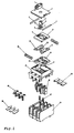
- the housing of the switch device comprises a body piece 15 and a contact bridge 16, the latter communicating via a slanted sliding surface with a lower sliding member 14.
- the contact bridge 16 is connected via springs 27 to a housing 28.
- the electrical contact is accomplished by virtue of moving the lower sliding member 14 which moves via the slanted surface 24 the moving contacts 25 of the contact bridge 16 in regard to the stationary contacts 26.
- Switch actuator springs 10 are adapted into the spaces remaining to both sides about the opening in the center of the lower sliding member 14, whereby the spring ends are held by pegs 12 of a spring-arming plate 11.
- a switch control shaft 14 is passed through openings of the lower sliding member 14, the spring-arming plate 11 and the upper sliding member 8.
- detent springs 3 arranged to rest on a detent cam made on the shaft 4.
- the lower end of the control shaft 4 is provided with cam tips 6, and transfer teeth 7 and 23 are made on the shaft section between the cam tips 6 and the detent cam 5.
- the mounting well of the body piece 15 is closed with a cover 2 and the manual control lever 1 of the switch device is attached to the upper end of the control shaft 4 passed through the cover 2.
- Locking shoulders 18 are provided in the latch slots made to the bottom of the mounting well of the body piece 15. The locking shoulders 18 serve to inhibit the movement of the lower sliding member 14 by catching the elastic fingers 22 of the lower sliding member 14.
- the function of the fingers 22 is controlled by the cam tips 6 made on the control shaft 4.
- the inside surface of the opening in the center of the spring-arming plate 11 is provided with teeth 13 with a pitch compatible with the transfer teeth 7 made on the control shaft 4.
- the opening in the upper sliding member 8 is contoured into an inside force-control cam surface 9 adapted to cooperate with the outermost tooth 23 of the transfer teeth 7 made on the control shaft 4 which is passed through the opening.
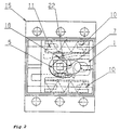
- Fig. 2 the switch is shown in its (open) position O .
- the transfer teeth 7 of the control shaft 4 has moved the spring-arming plate 11 to the right-hand side of the mounting well.
- the switch actuator springs 10 push the lower and upper sliding members 8 and 14 to the same side.
- the first locking finger 22 of the lower sliding member 14 rests abutting the locking shoulder 18 thus locking into a stationary position the lower sliding member 14 as well as the upper sliding member 8 fastened thereto by means of the fastening clips 20.
- the control shaft 4 is rotated clockwise, the transfer teeth 7 push the spring-arming plate 11 to the left, whereby the switch actuator springs 10 will be armed.
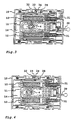
- Figs. 3 - 8 are shown the switch device components equivalent to those of the basic construction: control shaft 4, switch actuator springs 10, spring-arming plate 11, lower sliding member 14 and switch body piece 15. Additions in the present embodiment as compared to the basic construction are: trip lever 30, Trip actuator springs 31, interlock claw 32, latch slot 33, Trip brake 34 and slanted projection 35.
- the trip lever 30 is an elongated member passing through the switch body piece 15 and having its distal end extending into the interior of the switch mechanism connected to cooperate with the locking finger 22 (Fig. 2) that holds the switch in its position I .
- the trip lever 30 is so adapted in the switch body and positioned in respect to the locking finger 22 that the rotation of the trip lever 30 bends the locking finger 22 thus unlatching the lower sliding member 14 in a similar fashion as the rotation of the control shaft 4 by means of the manual control lever 1 toward position O of the switch.
- the trip lever 30 can be actuated by means of a solenoid.
- the Trip actuator springs 31 which are similar to the switch actuator springs 10, however, smaller and less stiff, are placed in the space between the outer cover 15 of the switch housing and the spring-arming plate 11.
- the function of the Trip actuator springs 31 is to exert on the spring-arming plate 11 such a force with respect to the body piece 15 that tends to shift the spring-arming plate 11 toward a position of the plate that corresponds to switch position O .
- a functional entity of the switch is formed by the combination: interlock claws 32 and slanted projection 35 at the edge of the spring-arming plate 11, latch slot 33 made to the lower sliding member 14 and Trip brake 34 adapted in the body piece 15.
- the Trip brake 34 is formed by a brake element proper and spring-like elements serving to push the tip of the brake element against the side surface of the lower sliding element 14.
- the tip of the brake element and the latch slot 33 at the side surface of the lower sliding element 14 are so shaped and placed that, when the lower sliding member 14 is essentially at the center of its travel, the tip of the brake element can enter the latch slot 33, thus inhibiting the movement of the lower sliding member 14 (Fig. 5).
- a precondition of this function is that the operation of the Trip brake 34 is not inhibited.
- the entry of the Trip brake 34 into the latch slot 33 can be inhibited by means of the interlock claw 32 or, alternatively, a projection with a slanted surface 35, both interlocking elements being situated at the edge of the spring-arming plate 11, on the same side of the switch housing as the Trip brake 34 and the latch slot 33.
- the interlock claw comprises one elongated part aligned parallel to the edge of the spring-arming plate 11 and a second part serving to connect said first part to the spring-arming plate 11.
- the outer edge of the elongated part is adapted in the width direction of the lower sliding member 14 so as to coincide with the edge of said member 14 and in its thickness direction so as to locate the elongated part essentially at the center of the tip of the Trip brake 34.
- the slanted projection 35 is placed correspondingly.
- the parts 32 and 35 are arranged so that, when viewed along the edge of the spring-arming plate 11 in the direction required to move the lower sliding member 14 from position O into position I of the plate 14 (direction O - I ), the first item is the fixing point of the interlock claw 32, followed by its elongated part.
- the slanted surface comprising the projection 35.
- the lengths and positions of the interlock claw 32 and the projection 35 in the longitudinal direction of the spring-arming plate 11 are determined so that the tripping of the Trip brake 34 is possible only when the mutual disposition of the spring-arming plate 11 and the lower sliding member 14 corresponds with a good accuracy to their mutual disposition in position I of the switch (Figs. 5 and 7).
- the tip of the Trip brake 34 can enter the latch slot 33 only when the spring-arming plate 11 is located essentially in the center area of its travel in regard to the lower sliding member 14.
- the tip of the Trip brake 34 is provided with such a hole or opening through which the elongated tip of the interlock claw 32 can enter when the Trip brake 34 is in an interlocking position to the movement of the lower sliding member 14. This means that the tripping of the Trip brake 34 will interlock the movement of the lower sliding member 14 but not the movement of the spring-arming plate 11.
- the switch device has three positions, namely position O , position I and position Trip. In the following, the state changeover between these positions is described.
- Fig. 3 is shown the switch device in position O , whereby the electric circuit controlled by the switch is opened. From position O , the switch can be thrown only into position I. This occurs by rotating the manual control lever 1, whereby the spring-arming plate 11 will move and the switch actuator springs 10 are armed. The interlock claw 32 of the spring-arming plate 11 moves into a position in front of the Trip brake 34 (Fig. 4) which at this moment rests against the edge of the lower sliding member 14. With a further rotation of the manual control lever 1, the switch mechanism will be triggered, and the lower sliding member 14 moves into position I (Fig. 7). The interlock claw 32 inhibits the operation of the Trip brake 34 at the instant the latch slot 33 of the lower sliding member 14 moves past the tip of the Trip brake 34.
- Fig. 7 the switch is shown in position I.
- the switch may change from this state into position Trip or position O .
- the manual control lever 1 To set the switch into position O , the manual control lever 1 must be rotated correspondingly in a direction which now is opposite to that required above for changing the switch state in direction O - I .
- the interlock claw 32 will inhibit the operation of the Trip brake 34 (Fig. 8).
- the switch can be triggered into position Trip by releasing the locking of the lower sliding member 14 through operating the trip lever 30. Then, the mechanical energy stored in the Trip actuator springs 31 will be released as the springs 31 push the spring-arming plate 11 and, via the stiffer switch actuator springs 10 connected thereto, further the lower sliding member 14 in direction I - O .
- both the length of the switch actuator springs 10 and simultaneously the mutual disposition of the lower sliding member 14 and the spring-arming plate remain essentially unchanged.
- the tip of the brake 34 can enter the latch slot 33, whereby the lower sliding member will be locked in position Trip as shown in Fig. 5.
- the switch position Trip is an intermediate state between position O and position I, whereby the lower sliding member 14 and the manual control lever 1, for instance, are located in the midway between their positions O and I .
- the switch is open when triggered into position Trip; however, if the switch is provided with a separate contact, the Trip state of the switch can be indicated to the remote-controlling system.
- the Trip state is illustrated in Fig. 5.
- the present invention can be implemented in a plurality of alternative manners.
- the application of the invention is not limited to merely improving the switch construction shown in Figs. 1 and 2, but rather, the remote-controllable trip mechanism according to the invention may as well be utilized in many other kinds of switches having their switching mechanism implemented in the form of a reciprocatingly moving sliding member.
- the use of such a switch need not necessarily be limited to the control of electrical energy.
- the implementation technique of the invention need not be limited by what is described above.
- the remote-controlled tripping is implemented by virtue of using a trip lever 30 to control a locking finger 22 resting against a locking shoulder 18.
- the tripping action may as well be carried out using any type of actuator mechanism such as a flexible cable or, alternatively, designing the switch device so that the locking finger can be directly actuated by a solenoid, for instance.
- a remote-controlled trip function by way of directly controlling the locking shoulder, and the concept of the invention may further be applied to switch designs having a latch mechanism different from that described above.
- the switch design shown in Figs. 3 - 8 has two Trip springs 31.
- the number of springs may as well be varied from one to four, for instance, and their size, shape and exact location in the switch construction may differ from those shown in the exemplifying embodiment.
- the springs may also be replaced by any other means capable of releasing at a desired instant a sufficient amount of energy to carry out the remote-controlled trip action.
- the switch may be designed for remote-controlled tripping into position Trip from position O .
- the switch could be closed (into position I ) in a remote-controlled manner. It is further possible to contemplate switch designs different from those described above having, for instance, the sliding members and spring-arming plates moving along circular paths.
Landscapes
- Push-Button Switches (AREA)
- Fuses (AREA)
- Selective Calling Equipment (AREA)
- Moulds For Moulding Plastics Or The Like (AREA)
- Control And Other Processes For Unpacking Of Materials (AREA)
- Pretreatment Of Seeds And Plants (AREA)
- Breeding Of Plants And Reproduction By Means Of Culturing (AREA)
- Breakers (AREA)
Claims (10)
- Schaltervorrichtung zum Steuern einer elektrischen Einrichtung, wobei die Vorrichtung aufweist:- ein Schaltergehäuse (28) mit stationären Kontaktflächen (26), die darin eingepasst sind und die zum Bereitstellen eines elektrischen Kontaktes dienen,- ein Trägerkörperelement (15), das in das Gehäuse (28) eingepasst ist,- bewegbare Kontaktflächen (25), die geeignet sind zum Inkontaktbringen mit den stationären Kontaktflächen (26), so dass ein elektrischer Kontakt ausgebildet wird,- wenigstens ein Gleitelement (14), das so in das Trägerkörperelement (15) eingepasst ist, dass es in einer Weise in Bezug auf das Trägerkörperelement (15) hin und her bewegbar ist, so dass bei Bewegung des Gleitelements (14) ein elektrischer Kontakt der bewegbaren Kontaktflächen (25) mit den stationären Kontaktflächen (26) bereitgestellt wird,- Mittel (6, 18, 22) zum Verriegeln des Gleitelements (14) in entweder einer Schließ-Position des Schalters, d.h. der elektrische Kontakt ist ausgebildet, oder in einer Offen-Position des Schalters, d.h. der elektrische Kontakt ist geöffnet, und ferner zum Entriegeln des Gleitelements (14) aus diesen Positionen,- wenigstens eine Federspannplatte (11), die so in das Trägerkörperelement (15) eingepasst ist, dass sie parallel zu der Bewegung des Gleitelements (14) bewegbar ist, und- wenigstens ein Elastikelement (10), das dazu dient, die Bewegung der Federspannplatte (11) an das Gleitelement zu übertragen,gekennzeichnet durch:- Mittel (33, 34, 35) zum Verriegeln des Gleitelements (14) in einer dritten Position zwischen der Schließ-Position und der Offen-Position und ferner zum Entriegeln des Gleitelements (14) aus der dritten Position,- einen anderen Satz von Mitteln (30), die so wirken an den Mitteln (6, 18, 22) zum Verriegeln des Gleitelements (14) in der Schließ-Position oder der Offen-Position des Schalters, dass sie das Gleitelement aus der Schließ-Position oder der Offen-Position fernentriegeln, und- Mittel (31), die in das Trägerkörperelement (15) eingepasst sind zum Speichern/Freigeben von Energie zum Verlagern des Gleitelements (14) aus der Schließ-/Offen-Position in die dritte Position.
- Schaltervorrichtung gemäß Anspruch 1, gekennzeichnet durch Mittel (32) zum bedingten Sperren der Funktion der zum in die dritte Position Verlagern des Gleitelements (14) angepassten Mittel (33, 34, 35).
- Schaltervorrichtung gemäß Anspruch 1, dadurch gekennzeichnet, dass die Mittel, die angepasst sind zum Verlagern des Gleitelements (14) in die dritte Position, aufweisen:- einen Verriegelungsschlitz (33), der an dem Gleitelement (14) an dessen Seite ausgebildet ist, die parallel zu seiner Bewegungsrichtung ist,- ein Hemmteil (34), das so in das Trägerkörperelement (15) eingepasst ist, dass es in Richtung zu der genannten Seite des Gleitelements (14) hin bewegbar ist, wobei das Hemmteil ein äußerstes Ende aufweist, das geeignet ist zum Eindringen in den Verriegelungsschlitz (33), und- Elastikelemente, wie beispielsweise Federn, die in einen zwischen dem Hemmteil (34) und dem Inneren des Trägerkörperelements (15) verbleibenden Raum eingepasst sind, wobei die Elastikelemente dazu dienen, das äußerste Ende des Hemmteils (34) in den Verriegelungsschlitz (33) hineinzudrücken, um das Gleitelement unter der Voraussetzung, dass das äußerste Ende des Hemmteils (34) und der Verriegelungsschlitz (33) übereinstimmen und der Bewegung des Hemmteils (34) keine mechanische Sperre (32) auferlegt ist, zu verriegeln.
- Schaltervorrichtung gemäß den Ansprüchen 2 und 3, dadurch gekennzeichnet, dass die Mittel zum bedingten Sperren des Eintretens des Hemmteils (34) in den Verriegelungsschlitz (33) eine Sperrklaue (32) aufweisen, die an der Seite der Federspannplatte (11) angebracht ist, die dem Hemmteil (34) zugewandt ist, wobei die Sperrklaue einen länglichen Abschnitt, der parallel zu der genannten Seite der Platte ausgerichtet ist, und einen anderen Abschnitt aufweist, der dazu dient, den länglichen Abschnitt von der genannten Seite der Platte zu distanzieren.
- Schaltervorrichtung gemäß Anspruch 4, dadurch gekennzeichnet, dass:- das äußerste Ende des Hemmteils (34) mit einer Öffnung versehen ist, die parallel zu der Seite der Federspannplatte (11) ausgerichtet ist, welche sich am nahesten an dem Hemmteil (34) befindet, und- der längliche Abschnitt der Sperrklaue (32) so angepasst ist, dass er durch die Öffnung hindurchdringen kann.
- Schaltervorrichtung gemäß Anspruch 3, dadurch gekennzeichnet, dass Mittel zum Herausheben des Hemmteils (34) aus dem Verriegelungsschlitz (33) und zum Entriegeln des Gleitelements (14) einen Vorsprung (35), der an der Seite der Federspannplatte (11) ausgebildet ist, die dem Hemmteil (34) zugewandt ist, und ferner eine schräge Fläche aufweisen, die an dem Vorsprung (35) so ausgebildet ist, dass sie bündig zu der genannten Seite der Federspannplatte (11) beginnt und sich schräg erstreckt, bis sie bündig mit der genannten Seite des Gleitelements (14) ist oder sich geringfügig über dieselbige hinaus erstreckt, wobei die schräge Fläche dazu dient, unter der von einer geeigneten Bewegung der Federspannplatte (11) ausgeübten Kraft das Hemmteil (34) aus seiner Position herauszuheben, in welcher es die Bewegung des Gleitelements (14) sperrt.
- Schaltervorrichtung gemäß Anspruch 1, dadurch gekennzeichnet, dass der zweite Satz von Mitteln zum Entriegeln des Gleitelements (14) aus der Schließ-/Offen-Position des Schalters einen länglichen Auslösehebel (30) aufweist, welcher partiell sowohl außerhalb als auch innerhalb des Schalter-Trägerkörperelements (15) angeordnet ist und welcher angepasst ist zum Steuern des Mittels (18, 22) zum Sperren der Bewegung des Gleitelements (14), so dass er die Bewegung des Gleitelements (14) entsperrt.
- Schaltervorrichtung gemäß Anspruch 7, dadurch gekennzeichnet, dass der Auslösehebel (30) angepasst ist für eine elektromagnetische Betätigung mittels eines Solenoids.
- Schaltervorrichtung gemäß Anspruch 1, dadurch gekennzeichnet, dass:- die Mittel, die angepasst sind zum Speichern/Freigeben von Energie zum Bewegen des Gleitelements (14) aus der Schließ-/Offen-Position in die dritte Position, wenigstens eine Feder (31) aufweisen, die zwischen das Trägerkörperelement (15) und die Federspannplatte (11) montiert ist,- jede der wenigstens einen Feder (31) durch Bewegen der Federspannplatte (11) gespannt werden kann, und- die von der wenigstens einen Feder (31) gespeicherte Energie in einer Weise freigegeben werden kann, dass die Bewegung der Federspannplatte (11) bewirkt wird.
- Schaltervorrichtung gemäß Anspruch 1, gekennzeichnet durch Kontakte, die gekoppelt sind mit den Mitteln (33, 34, 35) zum Verriegeln des Gleitelements (14) in der dritten Position, wobei die Kontakte dazu dienen, den Verrieglungszustand des Gleitelements (14) in der dritten Position auf der Basis der Position des Verriegelungsmittels (34) anzuzeigen.
Applications Claiming Priority (3)
| Application Number | Priority Date | Filing Date | Title |
|---|---|---|---|
| FI980243A FI103840B1 (fi) | 1998-02-03 | 1998-02-03 | Kytkinvarokkeen kaukolaukaisumekanismi |
| FI980243 | 1998-02-03 | ||
| PCT/FI1999/000065 WO1999040595A1 (en) | 1998-02-03 | 1999-01-29 | Remote trip mechanism of a switch device |
Publications (2)
| Publication Number | Publication Date |
|---|---|
| EP1053553A1 EP1053553A1 (de) | 2000-11-22 |
| EP1053553B1 true EP1053553B1 (de) | 2006-05-03 |
Family
ID=8550687
Family Applications (1)
| Application Number | Title | Priority Date | Filing Date |
|---|---|---|---|
| EP99900910A Expired - Lifetime EP1053553B1 (de) | 1998-02-03 | 1999-01-29 | Fernauslöser für eine schaltvorrichtung |
Country Status (9)
| Country | Link |
|---|---|
| US (1) | US6501039B1 (de) |
| EP (1) | EP1053553B1 (de) |
| CN (1) | CN1127742C (de) |
| AT (1) | ATE325421T1 (de) |
| CA (1) | CA2316801C (de) |
| DE (1) | DE69931147T2 (de) |
| ES (1) | ES2264251T3 (de) |
| FI (1) | FI103840B1 (de) |
| WO (1) | WO1999040595A1 (de) |
Cited By (3)
| Publication number | Priority date | Publication date | Assignee | Title |
|---|---|---|---|---|
| US8357867B2 (en) | 2008-06-19 | 2013-01-22 | Abb Oy | Controller unit for switching device |
| US8357868B2 (en) | 2008-06-19 | 2013-01-22 | Abb Oy | Controller unit for switching device |
| US8383973B2 (en) | 2008-06-19 | 2013-02-26 | Abb Oy | Tripping assembly for switching device |
Families Citing this family (4)
| Publication number | Priority date | Publication date | Assignee | Title |
|---|---|---|---|---|
| US7570139B2 (en) * | 2007-04-05 | 2009-08-04 | Eaton Corporation | Electrical switching apparatus, and trip actuator assembly and reset assembly therefor |
| US9530576B2 (en) | 2013-04-10 | 2016-12-27 | Savannah River Nuclear Solutions, Llc | Device for remote operation of electrical disconnect |
| US20140319962A1 (en) * | 2013-04-30 | 2014-10-30 | David Thomas Allen | Adjustable insulating cover for a bar-to-bar connection of a stator winding in a dynamoelectric machine |
| JP7286344B2 (ja) * | 2019-02-27 | 2023-06-05 | Idec株式会社 | 操作支援機能付き操作スイッチユニット、操作支援機能付き操作ユニットおよび操作支援システム |
Family Cites Families (3)
| Publication number | Priority date | Publication date | Assignee | Title |
|---|---|---|---|---|
| FI93502C (fi) | 1993-08-13 | 1995-04-10 | Abb Stroemberg Kojeet Oy | Kytkinlaite |
| US5689095A (en) * | 1993-09-20 | 1997-11-18 | Kabushiki Kaisha Tokai Rika Denki Seisakusho | Switching device |
| FR2753563B1 (fr) * | 1996-09-16 | 1998-10-16 | Schneider Electric Sa | Interrupteur electrique multipolaire ayant un barreau de commutation elementaire par pole |
-
1998
- 1998-02-03 FI FI980243A patent/FI103840B1/fi not_active IP Right Cessation
-
1999
- 1999-01-29 CA CA002316801A patent/CA2316801C/en not_active Expired - Fee Related
- 1999-01-29 WO PCT/FI1999/000065 patent/WO1999040595A1/en not_active Ceased
- 1999-01-29 US US09/600,200 patent/US6501039B1/en not_active Expired - Lifetime
- 1999-01-29 ES ES99900910T patent/ES2264251T3/es not_active Expired - Lifetime
- 1999-01-29 CN CN99802608A patent/CN1127742C/zh not_active Expired - Fee Related
- 1999-01-29 EP EP99900910A patent/EP1053553B1/de not_active Expired - Lifetime
- 1999-01-29 AT AT99900910T patent/ATE325421T1/de not_active IP Right Cessation
- 1999-01-29 DE DE69931147T patent/DE69931147T2/de not_active Expired - Lifetime
Cited By (3)
| Publication number | Priority date | Publication date | Assignee | Title |
|---|---|---|---|---|
| US8357867B2 (en) | 2008-06-19 | 2013-01-22 | Abb Oy | Controller unit for switching device |
| US8357868B2 (en) | 2008-06-19 | 2013-01-22 | Abb Oy | Controller unit for switching device |
| US8383973B2 (en) | 2008-06-19 | 2013-02-26 | Abb Oy | Tripping assembly for switching device |
Also Published As
| Publication number | Publication date |
|---|---|
| FI980243A0 (fi) | 1998-02-03 |
| CN1289444A (zh) | 2001-03-28 |
| FI103840B (fi) | 1999-09-30 |
| ATE325421T1 (de) | 2006-06-15 |
| WO1999040595A1 (en) | 1999-08-12 |
| EP1053553A1 (de) | 2000-11-22 |
| FI980243L (fi) | 1999-08-04 |
| US6501039B1 (en) | 2002-12-31 |
| DE69931147D1 (de) | 2006-06-08 |
| CA2316801C (en) | 2007-06-12 |
| CA2316801A1 (en) | 1999-08-12 |
| DE69931147T2 (de) | 2007-02-08 |
| ES2264251T3 (es) | 2006-12-16 |
| CN1127742C (zh) | 2003-11-12 |
| FI103840B1 (fi) | 1999-09-30 |
Similar Documents
| Publication | Publication Date | Title |
|---|---|---|
| EP0450699B1 (de) | Abschliessvorrichtung mittels Vorhängeschloss von Handbedienteilen elektromechanischer Einrichtungen | |
| US20100089874A1 (en) | Switchgear | |
| US5719363A (en) | Mechanical switching device such as a circuit breaker and a safety device for the circuit breaker | |
| US5777284A (en) | Safety switch assembly with a latch mechanism | |
| JPS63281393A (ja) | インターロックスイッチ基板装置 | |
| US6501039B1 (en) | Remote trip mechanism of a switch device | |
| CA2159928C (en) | Circuit breaker remote closing operator | |
| KR880001010A (ko) | 전기 단선 수단을 갖는 회로차단기 | |
| KR101366850B1 (ko) | 에너지 분배용 전기 개폐기 조립체를 위한 스위칭 디바이스 | |
| US6958456B1 (en) | Positive locking, trigger grip, external operating handle assembly for network protector enclosures | |
| US5828277A (en) | Contactor/circuit-breaker type switch device | |
| US6211758B1 (en) | Circuit breaker accessory gap control mechanism | |
| EP3729481B1 (de) | Drehgriffkonstruktion eines elektrischen schalters | |
| EP3667150B1 (de) | Verriegelungsvorrichtung | |
| CN220233067U (zh) | 脱扣机构及断路器 | |
| CA2048784C (en) | Molded case circuit breaker operating cradle configuration | |
| MXPA01011075A (es) | Actuador de desconexion de alta fuerza y rapida accion. | |
| JPH0430126B2 (de) | ||
| EP0479468B1 (de) | Schalter mit Koordination des Schalt- und Trennmechanismus | |
| JPH087717A (ja) | 開閉装置の操作機構 | |
| US20020158731A1 (en) | Circuit breaker actuator mechanism | |
| KR100584826B1 (ko) | 고압기기의 트리거장치 | |
| MXPA01011739A (es) | Dispositivo de control de interruptor de circuito. | |
| PL206733B1 (pl) | Wyłącznik silnikowy | |
| PL175405B1 (pl) | Wyłączniksilnikowy |
Legal Events
| Date | Code | Title | Description |
|---|---|---|---|
| PUAI | Public reference made under article 153(3) epc to a published international application that has entered the european phase |
Free format text: ORIGINAL CODE: 0009012 |
|
| 17P | Request for examination filed |
Effective date: 20000622 |
|
| AK | Designated contracting states |
Kind code of ref document: A1 Designated state(s): AT DE ES FR GB IT NL SE |
|
| GRAP | Despatch of communication of intention to grant a patent |
Free format text: ORIGINAL CODE: EPIDOSNIGR1 |
|
| GRAS | Grant fee paid |
Free format text: ORIGINAL CODE: EPIDOSNIGR3 |
|
| GRAA | (expected) grant |
Free format text: ORIGINAL CODE: 0009210 |
|
| AK | Designated contracting states |
Kind code of ref document: B1 Designated state(s): AT DE ES FR GB IT NL SE |
|
| PG25 | Lapsed in a contracting state [announced via postgrant information from national office to epo] |
Ref country code: IT Free format text: LAPSE BECAUSE OF FAILURE TO SUBMIT A TRANSLATION OF THE DESCRIPTION OR TO PAY THE FEE WITHIN THE PRESCRIBED TIME-LIMIT;WARNING: LAPSES OF ITALIAN PATENTS WITH EFFECTIVE DATE BEFORE 2007 MAY HAVE OCCURRED AT ANY TIME BEFORE 2007. THE CORRECT EFFECTIVE DATE MAY BE DIFFERENT FROM THE ONE RECORDED. Effective date: 20060503 Ref country code: AT Free format text: LAPSE BECAUSE OF FAILURE TO SUBMIT A TRANSLATION OF THE DESCRIPTION OR TO PAY THE FEE WITHIN THE PRESCRIBED TIME-LIMIT Effective date: 20060503 |
|
| RAP1 | Party data changed (applicant data changed or rights of an application transferred) |
Owner name: ABB OY |
|
| REG | Reference to a national code |
Ref country code: GB Ref legal event code: FG4D |
|
| REF | Corresponds to: |
Ref document number: 69931147 Country of ref document: DE Date of ref document: 20060608 Kind code of ref document: P |
|
| REG | Reference to a national code |
Ref country code: SE Ref legal event code: TRGR |
|
| ET | Fr: translation filed | ||
| REG | Reference to a national code |
Ref country code: ES Ref legal event code: FG2A Ref document number: 2264251 Country of ref document: ES Kind code of ref document: T3 |
|
| PLBE | No opposition filed within time limit |
Free format text: ORIGINAL CODE: 0009261 |
|
| STAA | Information on the status of an ep patent application or granted ep patent |
Free format text: STATUS: NO OPPOSITION FILED WITHIN TIME LIMIT |
|
| 26N | No opposition filed |
Effective date: 20070206 |
|
| REG | Reference to a national code |
Ref country code: FR Ref legal event code: PLFP Year of fee payment: 17 |
|
| PGFP | Annual fee paid to national office [announced via postgrant information from national office to epo] |
Ref country code: NL Payment date: 20150129 Year of fee payment: 17 |
|
| PGFP | Annual fee paid to national office [announced via postgrant information from national office to epo] |
Ref country code: IT Payment date: 20150130 Year of fee payment: 17 Ref country code: ES Payment date: 20150128 Year of fee payment: 17 Ref country code: DE Payment date: 20150121 Year of fee payment: 17 |
|
| PGFP | Annual fee paid to national office [announced via postgrant information from national office to epo] |
Ref country code: GB Payment date: 20150121 Year of fee payment: 17 Ref country code: SE Payment date: 20150121 Year of fee payment: 17 Ref country code: FR Payment date: 20150122 Year of fee payment: 17 |
|
| REG | Reference to a national code |
Ref country code: DE Ref legal event code: R119 Ref document number: 69931147 Country of ref document: DE |
|
| GBPC | Gb: european patent ceased through non-payment of renewal fee |
Effective date: 20160129 |
|
| REG | Reference to a national code |
Ref country code: NL Ref legal event code: MM Effective date: 20160201 |
|
| REG | Reference to a national code |
Ref country code: FR Ref legal event code: ST Effective date: 20160930 |
|
| PG25 | Lapsed in a contracting state [announced via postgrant information from national office to epo] |
Ref country code: DE Free format text: LAPSE BECAUSE OF NON-PAYMENT OF DUE FEES Effective date: 20160802 Ref country code: GB Free format text: LAPSE BECAUSE OF NON-PAYMENT OF DUE FEES Effective date: 20160129 |
|
| PG25 | Lapsed in a contracting state [announced via postgrant information from national office to epo] |
Ref country code: FR Free format text: LAPSE BECAUSE OF NON-PAYMENT OF DUE FEES Effective date: 20160201 Ref country code: SE Free format text: LAPSE BECAUSE OF NON-PAYMENT OF DUE FEES Effective date: 20160130 Ref country code: NL Free format text: LAPSE BECAUSE OF NON-PAYMENT OF DUE FEES Effective date: 20160201 |
|
| PG25 | Lapsed in a contracting state [announced via postgrant information from national office to epo] |
Ref country code: IT Free format text: LAPSE BECAUSE OF NON-PAYMENT OF DUE FEES Effective date: 20160129 |
|
| REG | Reference to a national code |
Ref country code: ES Ref legal event code: FD2A Effective date: 20170224 |
|
| PG25 | Lapsed in a contracting state [announced via postgrant information from national office to epo] |
Ref country code: ES Free format text: LAPSE BECAUSE OF NON-PAYMENT OF DUE FEES Effective date: 20160130 |