EP1053718A1 - Clou de verrouillage pour le traitement des fractures de la tige fémorale - Google Patents
Clou de verrouillage pour le traitement des fractures de la tige fémorale Download PDFInfo
- Publication number
- EP1053718A1 EP1053718A1 EP00810321A EP00810321A EP1053718A1 EP 1053718 A1 EP1053718 A1 EP 1053718A1 EP 00810321 A EP00810321 A EP 00810321A EP 00810321 A EP00810321 A EP 00810321A EP 1053718 A1 EP1053718 A1 EP 1053718A1
- Authority
- EP
- European Patent Office
- Prior art keywords
- nail
- section
- locking nail
- locking
- proximal
- Prior art date
- Legal status (The legal status is an assumption and is not a legal conclusion. Google has not performed a legal analysis and makes no representation as to the accuracy of the status listed.)
- Granted
Links
Images

Classifications
-
- A—HUMAN NECESSITIES
- A61—MEDICAL OR VETERINARY SCIENCE; HYGIENE
- A61B—DIAGNOSIS; SURGERY; IDENTIFICATION
- A61B17/00—Surgical instruments, devices or methods
- A61B17/56—Surgical instruments or methods for treatment of bones or joints; Devices specially adapted therefor
- A61B17/58—Surgical instruments or methods for treatment of bones or joints; Devices specially adapted therefor for osteosynthesis, e.g. bone plates, screws or setting implements
- A61B17/68—Internal fixation devices, including fasteners and spinal fixators, even if a part thereof projects from the skin
- A61B17/72—Intramedullary devices, e.g. pins or nails
- A61B17/7233—Intramedullary devices, e.g. pins or nails with special means of locking the nail to the bone
-
- A—HUMAN NECESSITIES
- A61—MEDICAL OR VETERINARY SCIENCE; HYGIENE
- A61B—DIAGNOSIS; SURGERY; IDENTIFICATION
- A61B17/00—Surgical instruments, devices or methods
- A61B17/56—Surgical instruments or methods for treatment of bones or joints; Devices specially adapted therefor
- A61B17/58—Surgical instruments or methods for treatment of bones or joints; Devices specially adapted therefor for osteosynthesis, e.g. bone plates, screws or setting implements
- A61B17/68—Internal fixation devices, including fasteners and spinal fixators, even if a part thereof projects from the skin
- A61B17/72—Intramedullary devices, e.g. pins or nails
-
- A—HUMAN NECESSITIES
- A61—MEDICAL OR VETERINARY SCIENCE; HYGIENE
- A61B—DIAGNOSIS; SURGERY; IDENTIFICATION
- A61B17/00—Surgical instruments, devices or methods
- A61B17/56—Surgical instruments or methods for treatment of bones or joints; Devices specially adapted therefor
- A61B17/58—Surgical instruments or methods for treatment of bones or joints; Devices specially adapted therefor for osteosynthesis, e.g. bone plates, screws or setting implements
- A61B17/68—Internal fixation devices, including fasteners and spinal fixators, even if a part thereof projects from the skin
- A61B17/74—Devices for the head or neck or trochanter of the femur
- A61B17/742—Devices for the head or neck or trochanter of the femur having one or more longitudinal elements oriented along or parallel to the axis of the neck
- A61B17/744—Devices for the head or neck or trochanter of the femur having one or more longitudinal elements oriented along or parallel to the axis of the neck the longitudinal elements coupled to an intramedullary nail
Definitions
- the invention relates to a locking nail for the supply of Femoral shaft fractures, also in connection with trochanteric femoral fractures, according to the preamble of claim 1.
- An osteosynthesis aid is known from the publication EP 0 528 128 Treatment of intertrochanteric or subtrochanteric femoral fractures known which as a locking nail with an open cloverleaf profile is designed.
- the locking nail points in its proximal Section oblique bores for guiding and holding one Femoral neck screw on.
- the locking nail points to its distal Section an axial longitudinal slot.
- the locking nail points also at the transition between a proximal section and a distal section a kink.
- a disadvantage of this known Locking nail is the fact that it is difficult in the medullary canal is to be introduced ..
- the object of the present invention is a more advantageous one To create a locking nail to treat femoral shaft fractures.
- Sub-claims 2 to 13 relate to further, advantageous embodiments of the locking nail according to the invention.
- the task is solved in particular with a locking nail comprising a proximal nail section and one thereon subsequent distal nail section, these nail sections Have holes for receiving bone screws, and wherein the distal nail section a in the anterior-posterior plane curvature corresponding essentially to the antecurvation of the femur has, and wherein the proximal nail section at least over one Section a continuous in a lateral-medial plane Has curvature, in particular with a constant radius of curvature.
- continuous curvature is further understood to mean that the curvature has no point with a discontinuity or no kink, which can also be described mathematically in such a way that the first derivative of the curvature course has no discontinuity or no sudden change.
- the proximal nail section has starting from the distal nail section, a transition section and then a fastening section with holes for Inclusion of the bone screws, the transition section as well the fastening section has a continuous curvature with constant Have radius of curvature.
- the locking nail according to the invention is in particular for supply of femoral shaft fractures, also in connection with trochanteric Femur fractures are suitable, the locking nail due to the interdividually different anatomical design of the femur, with Lengths of about 300 mm to 500 mm is manufactured.
- the locking nail is characterized by a good mechanical hold in the medullary cavity and has a good security against rotation.
- In the lower distal Nail section is a transverse bore through which a Bone screw is inserted to the locking nail axially and in Hold the direction of rotation firmly.
- the proximal nail section points preferably an oblique hole through which a Femoral neck screw is insertable.
- the locking nail according to the invention is preferably as one continuous hollow tube, in particular as a cylindrical hollow tube designed and consists of a body-compatible, non-corroding Material such as titanium or a titanium alloy.
- a hollow wire is preferably inserted through a guide wire.
- the Locking nail could, however, also be designed in the form of a rod and have no hollow interior extending in the axial direction.
- An advantage of the locking nail according to the invention is the fact that this, even in an embodiment with low elasticity, without greater force can be introduced into the medullary canal.
- the Embodiment with low elasticity ensures a very good one mechanical hold and a good support function in the medullary cavity.
- the locking nail according to the invention is designed such that this preferably starting from the greater trochanter into the femur or is introduced in the medullary canal, the Insertion site preferably slightly lateral to the tip of the trochanter major is arranged. Because the greater trochanter, compared to the previous one usual insertion point on the femur, closer to the surface of the skin arranged, the insertion over the greater trochanter has the advantage on that a smaller opening of the operating field is required, which especially reduces the risk of infections. In addition, the trochanter major easier in the activities required during the operation accessible. Usually a locking nail in the area of Fossa piriformis introduced into the medullary canal.
- the locking nail has a Fastening section with a relatively small cross section. This allows a locking nail with an overall small cross section form what is beneficial to insertion into the medullary canal also requires only a small opening of the operating field.
- the locking nail known from the cited document points to the Transition point between the distal and the proximal nail section a kink and is therefore, despite the through the longitudinal slot in the distal nail section caused elasticity, difficult in the medullary cavity introduce because the medullary canal has a curved course, and this nail in certain places on the medullary wall or on the Cancellous bone is applied and only with greater force in the medullary canal can be introduced.
- the locking nail according to the invention with the curved running proximal nail section has the advantage that this taking the anatomical course of the medullary cavity into account in such an advantageous manner that it can be inserted without much effort.
- Locking nail In contrast to Short locking nails must be very long according to the invention designed locking nail during insertion into the medullary canal be rotated by a partial rotation about its longitudinal axis.
- the Locking nail according to the invention has the property that during the insertion into the medullary canal correct end position rotates because of the external shape of the locking nail modeled the course of the medullary canal with regard to essential aspects is.
- the locking nail known from the cited publication instructs the transition point between the proximal and distal nail sections a kink on what an automatic turning during insertion into the Medullary canal prevented.
- Locking nail has the further disadvantage that that in the medullary canal inserted nail can only be rotated to a limited extent, since material is in the longitudinal slot protrudes and forms an obstacle while turning. Since the locking nail according to the invention does not necessarily have a longitudinal slot needs, it is also cheaper to manufacture.
- the locking nail according to the invention can have a low elasticity have and still safe and without great effort in the Medullary canal are introduced.
- the locking nail is inserted into the medullary canal a larger one, approximately radially outward with respect to the course of the femur directed, especially weakening the cortical of the femur or destructive power avoided.
- This also enables the Femur is held together in its anatomically correct position. It is known to cause an unfavorably designed locking nail the fracture of the femur can follow the course of the Locking nail adjusts, which means that the fixed femur a Malposition or a deviation from the normal position having.
- the locking nail 1 is formed in one piece and consists of a proximal nail section 2 and one on it subsequent distal nail section 3.
- the proximal nail section 2 comprises the end 1a of the locking nail 1 a straight thread section 2c with an internal thread 2d, then a fastening section 2b, which a Cross hole 2i, an oval cross hole 2h, and two oblique holes 2e, 2f, and then a transition section 2a, which extends conically tapering to the distal nail section 3.
- the Surface of the fastening portion 2b has a parallel to the Oblique bores 2e, 2f extending groove 2g.
- This will preferably used a target device or an impact tool, which at in the femur locking nail 1 temporarily in the Internal thread 2d of the threaded portion 2c is screwed to the Screw in the bone screws precisely.
- the distal section extends Nail section 3 to the distal nail end 1b. Between the proximal Nail end 1a and the distal nail end 1b is the one in the middle of the Locking nail 1 center line 1c shown.
- the anterior-posterior plane apE runs according to the observation level Fig. 1.
- the distal nail section 3 has one in this anterior-posterior plane apE running curvature, which essentially is designed in accordance with the antecurvation of the femur.
- the curvature of the distal nail section 3 or its Center line 1c is designed as a segment of a circle, the radius of curvature R1, depending on the anatomical shape of the femur, for example 2 meters is.
- In the distal nail section 3 there are transverse bores 3a, 3b, 3d and an oval cross hole 3c for receiving bone screws appropriate.
- Fig. 1 is also perpendicular to the viewing plane or the anterior-posterior plane apE running lateral-medial plane ImE shown.
- the lateral-medial level ImE runs correspondingly to the observation level according to FIG. 2.
- FIG. 2 the one perpendicular to the viewing plane or to the lateral-medial-plane ImE anterior-posterior-plane apE shown.
- the front view of the locking nail 1 from direction A according to FIG. 2 shows the straight from this point of view in the lateral-medial plane ImE extending distal nail section 3, on which the two, one common curvature with constant radius of curvature R2 Connect transition section 2a and fastening section 2b.
- the subsequent threaded section 2c is shown in the Embodiment designed straight, but could also be curved and in particular the same Have radius of curvature R2.
- the subsection 2a, 2b respectively the center line 1c, which runs in the lateral-medial plane ImE, has one constant radius of curvature R2, and extends in the axial direction at least about a quarter of the total length of the locking nail 1, and preferably about a third of the total length.
- the detailed view from direction D shown in FIG. 4 shows part of the proximal nail section 2, namely the fastening section 2b and the threaded portion 2c.
- the openings are in the fastening section 2b the first and second oblique bores 2e, 2f, the notch 2g and part of the oval cross hole 2h visible.
- the Notches 2l, the oblique holes 2e, 2f and the oval cross hole 2h all run in the same level S2.
- the oblique bores 2e, 2f could also be used not parallel to each other.
- FIG. 7 shows a view from the direction F of a section of the fastening section 2b with oblique bores 2e, 2f and notch 2g, the direction F running parallel to the center lines 2m, 2l.
- a screw 6 with a center line 2n is arranged in the ventrally arranged notch 2g.
- the center lines 2m, 2l, 2n are spaced apart to form an isosceles triangle, the center lines 2m, 2l running through the center line 1c of the locking nail 1.
- the distance between the center lines 2l, 2n and the center lines 2m, 2n is, for example, 8 mm.
- the proximal nail section 2 is firmly connected to the femur by one, two or three screws 6, which are arranged to run through the two oblique bores 2e, 2f and the notch 2g.
- This arrangement of two oblique bores 2e, 2f and the notch 2g has the advantage that the diameter of the proximal nail section 2 can be made relatively thin and nevertheless a secure anchoring of the locking nail 1 by means of bone screws 6 is possible.
- the locking nail 1 can for example be configured such that the proximal nail section 2 has a diameter between 13 and 15 mm and the distal nail section 3 has a diameter between 9 and 13 mm.
- Such a thin locking nail 1 has the advantage that only a small opening of the operating field is required for its implantation.
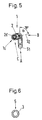
- FIG. 5 shows a front view of the proximal nail end 1a from the direction E.
- the locking nail 1 runs along the proximal nail section 2 in a left curve and, after the transition into the distal nail section 3, runs in a downward-pointing curve.
- a plane S1 running perpendicularly through the distal nail section 3 and the plane S2 running through the notches 2l, the oblique bores 2e, 2f and the oval transverse bore 2h intersect at an angle of 78 degrees.
- the proximal nail section 2 thus has an anti-torsion of 78 degrees with respect to the distal nail section 1.
- This antetorsion is necessary so that the oblique bores 2e, 2f or the transverse bore 2h run in the direction of the femoral neck or the femoral head when the locking nail 1 is inserted in the femur.
- the antetorsion is preferably between 75 degrees and 80 degrees.
- the German term " antetorsion” is called " anteversion" in English.
- Fig. 3 shows the locking nail 1 from the viewing direction C, which runs perpendicular to plane S2.
- the locking nail 1 according to FIG. 3 is 12 degrees shown rotated about its longitudinal axis.
- the cutting plane through the proximal nail section 2 corresponds to plane S2 and runs parallel to Viewing level.
- Fig. 6 shows a section through a further embodiment of a distal nail section 3, which one in the longitudinal direction extending gap 5 has around the nail section 3 a higher To give elasticity.
- the locking nail 1 shown in Figures 1 to 5 is for one left femur determined. Due to the physiological antecurvation and Antetorsion of the femur is a right and a left version of the Locking nail 1 required.
Landscapes
- Health & Medical Sciences (AREA)
- Orthopedic Medicine & Surgery (AREA)
- Surgery (AREA)
- Life Sciences & Earth Sciences (AREA)
- Heart & Thoracic Surgery (AREA)
- Nuclear Medicine, Radiotherapy & Molecular Imaging (AREA)
- Engineering & Computer Science (AREA)
- Biomedical Technology (AREA)
- Neurology (AREA)
- Medical Informatics (AREA)
- Molecular Biology (AREA)
- Animal Behavior & Ethology (AREA)
- General Health & Medical Sciences (AREA)
- Public Health (AREA)
- Veterinary Medicine (AREA)
- Surgical Instruments (AREA)
Priority Applications (1)
| Application Number | Priority Date | Filing Date | Title |
|---|---|---|---|
| EP20000810321 EP1053718B1 (fr) | 1999-05-12 | 2000-04-13 | Clou de verrouillage pour le traitement des fractures de la tige fémorale |
Applications Claiming Priority (3)
| Application Number | Priority Date | Filing Date | Title |
|---|---|---|---|
| EP99810422 | 1999-05-12 | ||
| EP99810422 | 1999-05-12 | ||
| EP20000810321 EP1053718B1 (fr) | 1999-05-12 | 2000-04-13 | Clou de verrouillage pour le traitement des fractures de la tige fémorale |
Publications (2)
| Publication Number | Publication Date |
|---|---|
| EP1053718A1 true EP1053718A1 (fr) | 2000-11-22 |
| EP1053718B1 EP1053718B1 (fr) | 2008-07-09 |
Family
ID=26073852
Family Applications (1)
| Application Number | Title | Priority Date | Filing Date |
|---|---|---|---|
| EP20000810321 Expired - Lifetime EP1053718B1 (fr) | 1999-05-12 | 2000-04-13 | Clou de verrouillage pour le traitement des fractures de la tige fémorale |
Country Status (1)
| Country | Link |
|---|---|
| EP (1) | EP1053718B1 (fr) |
Cited By (14)
| Publication number | Priority date | Publication date | Assignee | Title |
|---|---|---|---|---|
| WO2003030749A1 (fr) * | 2001-10-12 | 2003-04-17 | Flores Davila Jorge P | Clou centro-medullaire a rainure et methode d'osteosynthese de segments diaphysaires |
| WO2005020830A1 (fr) * | 2003-08-29 | 2005-03-10 | Synthes Gmbh | Clou intramedullaire |
| EP1935361A1 (fr) * | 2006-12-19 | 2008-06-25 | Zimmer Technology, Inc. | Système de fixation d'os |
| US7892234B2 (en) | 2004-06-22 | 2011-02-22 | Synthes Usa, Llc | Intramedullary nail |
| US8066706B2 (en) | 2004-06-30 | 2011-11-29 | Synthes Usa, Llc | Surgical nail |
| US8465489B2 (en) | 2003-06-12 | 2013-06-18 | Synthes Usa, Llc | Surgical nail |
| US8808292B2 (en) | 2008-11-11 | 2014-08-19 | Zimmer Gmbh | Orthopedic screw |
| US8888779B2 (en) | 2003-03-07 | 2014-11-18 | DePuy Synthes Products, LLC | Locking screw for an intramedullary nail |
| US9237909B2 (en) | 2003-07-30 | 2016-01-19 | DePuy Synthes Products, Inc. | Surgical nail |
| US9737347B2 (en) | 2003-06-12 | 2017-08-22 | DePuy Synthes Products, Inc. | Surgical nail |
| US9918757B2 (en) | 2001-10-17 | 2018-03-20 | DePuy Synthes Products, Inc. | Bone fixation system |
| CN111655177A (zh) * | 2018-02-07 | 2020-09-11 | In2博恩斯公司 | 改进的关节固定装置 |
| EP3928727A1 (fr) * | 2020-06-22 | 2021-12-29 | Changzhou Kanghui Medical Innovation Co., Ltd. | Clou principal pour système de clou intramédullaire et le système de clou intramédullaire |
| US11446072B2 (en) | 2017-10-10 | 2022-09-20 | DePuy Synthes Products, Inc. | Self-retaining nail to insertion handle interface |
Families Citing this family (1)
| Publication number | Priority date | Publication date | Assignee | Title |
|---|---|---|---|---|
| US12004785B2 (en) | 2022-04-21 | 2024-06-11 | DePuy Synthes Products, Inc. | Retrograde femoral intramedullary nail, and related systems and methods |
Citations (4)
| Publication number | Priority date | Publication date | Assignee | Title |
|---|---|---|---|---|
| US2518019A (en) * | 1946-11-29 | 1950-08-08 | Kane John Timothy | Intramedullary splint |
| US4135507A (en) * | 1977-05-20 | 1979-01-23 | Harris Leslie J | Condylocephalic nail for fixation of pertrochanteric fractures |
| EP0355411A1 (fr) * | 1988-08-10 | 1990-02-28 | Ace Medical Company | Broche intramédullaire pour stabiliser le fémur |
| EP0528128A1 (fr) | 1991-08-09 | 1993-02-24 | Howmedica GmbH | Clou centromédullaire destiné ou traitement de fractures centrales et trochantértiennes du fémur |
-
2000
- 2000-04-13 EP EP20000810321 patent/EP1053718B1/fr not_active Expired - Lifetime
Patent Citations (4)
| Publication number | Priority date | Publication date | Assignee | Title |
|---|---|---|---|---|
| US2518019A (en) * | 1946-11-29 | 1950-08-08 | Kane John Timothy | Intramedullary splint |
| US4135507A (en) * | 1977-05-20 | 1979-01-23 | Harris Leslie J | Condylocephalic nail for fixation of pertrochanteric fractures |
| EP0355411A1 (fr) * | 1988-08-10 | 1990-02-28 | Ace Medical Company | Broche intramédullaire pour stabiliser le fémur |
| EP0528128A1 (fr) | 1991-08-09 | 1993-02-24 | Howmedica GmbH | Clou centromédullaire destiné ou traitement de fractures centrales et trochantértiennes du fémur |
Cited By (17)
| Publication number | Priority date | Publication date | Assignee | Title |
|---|---|---|---|---|
| WO2003030749A1 (fr) * | 2001-10-12 | 2003-04-17 | Flores Davila Jorge P | Clou centro-medullaire a rainure et methode d'osteosynthese de segments diaphysaires |
| US10271881B2 (en) | 2001-10-17 | 2019-04-30 | DePuy Synthes Products, Inc. | Bone fixation system |
| US9918757B2 (en) | 2001-10-17 | 2018-03-20 | DePuy Synthes Products, Inc. | Bone fixation system |
| US8888779B2 (en) | 2003-03-07 | 2014-11-18 | DePuy Synthes Products, LLC | Locking screw for an intramedullary nail |
| US9737347B2 (en) | 2003-06-12 | 2017-08-22 | DePuy Synthes Products, Inc. | Surgical nail |
| US8465489B2 (en) | 2003-06-12 | 2013-06-18 | Synthes Usa, Llc | Surgical nail |
| US9237909B2 (en) | 2003-07-30 | 2016-01-19 | DePuy Synthes Products, Inc. | Surgical nail |
| WO2005020830A1 (fr) * | 2003-08-29 | 2005-03-10 | Synthes Gmbh | Clou intramedullaire |
| US8221419B2 (en) | 2003-08-29 | 2012-07-17 | Synthes Usa, Llc | Intramedullary nail |
| US9814500B2 (en) | 2003-08-29 | 2017-11-14 | DePuy Synthes Products, Inc. | Intramedullary nail |
| US7892234B2 (en) | 2004-06-22 | 2011-02-22 | Synthes Usa, Llc | Intramedullary nail |
| US8066706B2 (en) | 2004-06-30 | 2011-11-29 | Synthes Usa, Llc | Surgical nail |
| EP1935361A1 (fr) * | 2006-12-19 | 2008-06-25 | Zimmer Technology, Inc. | Système de fixation d'os |
| US8808292B2 (en) | 2008-11-11 | 2014-08-19 | Zimmer Gmbh | Orthopedic screw |
| US11446072B2 (en) | 2017-10-10 | 2022-09-20 | DePuy Synthes Products, Inc. | Self-retaining nail to insertion handle interface |
| CN111655177A (zh) * | 2018-02-07 | 2020-09-11 | In2博恩斯公司 | 改进的关节固定装置 |
| EP3928727A1 (fr) * | 2020-06-22 | 2021-12-29 | Changzhou Kanghui Medical Innovation Co., Ltd. | Clou principal pour système de clou intramédullaire et le système de clou intramédullaire |
Also Published As
| Publication number | Publication date |
|---|---|
| EP1053718B1 (fr) | 2008-07-09 |
Similar Documents
| Publication | Publication Date | Title |
|---|---|---|
| EP1233712B1 (fr) | Clou intramedullaire | |
| EP0528128B1 (fr) | Clou centromédullaire destiné ou traitement de fractures centrales et trochantértiennes du fémur | |
| DE60014042T2 (de) | Axialer äusserer Fixateur | |
| DE4318150C2 (de) | Osteosynthese-Hilfsmittel zur Versorgung subtrochanterer und pertrochanterer Frakturen sowie von Schenkelhalsfrakturen | |
| DE3541597C2 (fr) | ||
| DE69717741T2 (de) | Suprakondylärer Knochennagel | |
| DE69211429T2 (de) | Intramedulläre, intertrochanterische Bruchfixierungvorrichtung | |
| DE69218389T2 (de) | Verriegelungsnagel für die Versorgung von Frakturen des proximalen Femurs | |
| EP1053718B1 (fr) | Clou de verrouillage pour le traitement des fractures de la tige fémorale | |
| DE9115200U1 (de) | Verriegelungsnagel für die Versorgung von Frakturen der Röhrenknochen | |
| WO2005020830A1 (fr) | Clou intramedullaire | |
| EP0715832B1 (fr) | Broche intramédullaire pour compression de la hanche | |
| DE20113345U1 (de) | Femurfrakturnagel | |
| EP1455662A1 (fr) | Dispositif de visee destine a une broche a fracture | |
| DE19703987C1 (de) | Zielgerät für ein Implantat zur Versorgung trochanterer und subtrochanterer Frakturen | |
| EP2029037B1 (fr) | Implant de tête fémorale | |
| DE8213228U1 (de) | Implantat zur Versorgung von trochanteren Oberschenkelfrakturen | |
| WO2003053265A1 (fr) | Clou modulaire pour os | |
| EP2934355A1 (fr) | Clou médullaire verrouillable comportant des passages pour fil de guidage | |
| DE9421911U1 (de) | Osteosynthese-Hilfsmittel zur Versorgung subtrochanterer, pertrochanterer und Schenkelhalsfrakturen | |
| DE202004018748U1 (de) | Modularer proximaler Femurnagel | |
| AT527951A1 (de) | Einrichtung zum Aufbringen einer Zugkraft auf eine Knochenschraube und Set mit dieser | |
| DE69620872T2 (de) | Markraumnagel für den einsatz zur femurverlängerung | |
| DE29916803U1 (de) | Proximaler Humerusnagel | |
| DE29923467U1 (de) | Marknagel |
Legal Events
| Date | Code | Title | Description |
|---|---|---|---|
| PUAI | Public reference made under article 153(3) epc to a published international application that has entered the european phase |
Free format text: ORIGINAL CODE: 0009012 |
|
| AK | Designated contracting states |
Kind code of ref document: A1 Designated state(s): AT BE CH CY DE DK ES FI FR GB GR IE IT LI LU MC NL PT SE |
|
| AX | Request for extension of the european patent |
Free format text: AL;LT;LV;MK;RO;SI |
|
| 17P | Request for examination filed |
Effective date: 20010425 |
|
| AKX | Designation fees paid |
Free format text: AT BE CH CY DE DK ES FI FR GB GR IE IT LI LU MC NL PT SE |
|
| RAP1 | Party data changed (applicant data changed or rights of an application transferred) |
Owner name: ZIMMER GMBH |
|
| GRAP | Despatch of communication of intention to grant a patent |
Free format text: ORIGINAL CODE: EPIDOSNIGR1 |
|
| GRAS | Grant fee paid |
Free format text: ORIGINAL CODE: EPIDOSNIGR3 |
|
| GRAA | (expected) grant |
Free format text: ORIGINAL CODE: 0009210 |
|
| AK | Designated contracting states |
Kind code of ref document: B1 Designated state(s): AT BE CH CY DE DK ES FI FR GB GR IE IT LI LU MC NL PT SE |
|
| REG | Reference to a national code |
Ref country code: GB Ref legal event code: FG4D Free format text: NOT ENGLISH |
|
| REG | Reference to a national code |
Ref country code: CH Ref legal event code: EP |
|
| REF | Corresponds to: |
Ref document number: 50015249 Country of ref document: DE Date of ref document: 20080821 Kind code of ref document: P |
|
| REG | Reference to a national code |
Ref country code: IE Ref legal event code: FG4D Free format text: LANGUAGE OF EP DOCUMENT: GERMAN |
|
| NLV1 | Nl: lapsed or annulled due to failure to fulfill the requirements of art. 29p and 29m of the patents act | ||
| PG25 | Lapsed in a contracting state [announced via postgrant information from national office to epo] |
Ref country code: NL Free format text: LAPSE BECAUSE OF FAILURE TO SUBMIT A TRANSLATION OF THE DESCRIPTION OR TO PAY THE FEE WITHIN THE PRESCRIBED TIME-LIMIT Effective date: 20080709 Ref country code: PT Free format text: LAPSE BECAUSE OF FAILURE TO SUBMIT A TRANSLATION OF THE DESCRIPTION OR TO PAY THE FEE WITHIN THE PRESCRIBED TIME-LIMIT Effective date: 20081209 Ref country code: ES Free format text: LAPSE BECAUSE OF FAILURE TO SUBMIT A TRANSLATION OF THE DESCRIPTION OR TO PAY THE FEE WITHIN THE PRESCRIBED TIME-LIMIT Effective date: 20081020 |
|
| PG25 | Lapsed in a contracting state [announced via postgrant information from national office to epo] |
Ref country code: FI Free format text: LAPSE BECAUSE OF FAILURE TO SUBMIT A TRANSLATION OF THE DESCRIPTION OR TO PAY THE FEE WITHIN THE PRESCRIBED TIME-LIMIT Effective date: 20080709 |
|
| REG | Reference to a national code |
Ref country code: IE Ref legal event code: FD4D |
|
| PG25 | Lapsed in a contracting state [announced via postgrant information from national office to epo] |
Ref country code: DK Free format text: LAPSE BECAUSE OF FAILURE TO SUBMIT A TRANSLATION OF THE DESCRIPTION OR TO PAY THE FEE WITHIN THE PRESCRIBED TIME-LIMIT Effective date: 20080709 Ref country code: IE Free format text: LAPSE BECAUSE OF FAILURE TO SUBMIT A TRANSLATION OF THE DESCRIPTION OR TO PAY THE FEE WITHIN THE PRESCRIBED TIME-LIMIT Effective date: 20080709 |
|
| PLBE | No opposition filed within time limit |
Free format text: ORIGINAL CODE: 0009261 |
|
| STAA | Information on the status of an ep patent application or granted ep patent |
Free format text: STATUS: NO OPPOSITION FILED WITHIN TIME LIMIT |
|
| 26N | No opposition filed |
Effective date: 20090414 |
|
| BERE | Be: lapsed |
Owner name: ZIMMER GMBH Effective date: 20090430 |
|
| PG25 | Lapsed in a contracting state [announced via postgrant information from national office to epo] |
Ref country code: SE Free format text: LAPSE BECAUSE OF FAILURE TO SUBMIT A TRANSLATION OF THE DESCRIPTION OR TO PAY THE FEE WITHIN THE PRESCRIBED TIME-LIMIT Effective date: 20081009 |
|
| PG25 | Lapsed in a contracting state [announced via postgrant information from national office to epo] |
Ref country code: MC Free format text: LAPSE BECAUSE OF NON-PAYMENT OF DUE FEES Effective date: 20090430 |
|
| PG25 | Lapsed in a contracting state [announced via postgrant information from national office to epo] |
Ref country code: BE Free format text: LAPSE BECAUSE OF NON-PAYMENT OF DUE FEES Effective date: 20090430 |
|
| PG25 | Lapsed in a contracting state [announced via postgrant information from national office to epo] |
Ref country code: AT Free format text: LAPSE BECAUSE OF NON-PAYMENT OF DUE FEES Effective date: 20090413 |
|
| PG25 | Lapsed in a contracting state [announced via postgrant information from national office to epo] |
Ref country code: GR Free format text: LAPSE BECAUSE OF FAILURE TO SUBMIT A TRANSLATION OF THE DESCRIPTION OR TO PAY THE FEE WITHIN THE PRESCRIBED TIME-LIMIT Effective date: 20081010 |
|
| PG25 | Lapsed in a contracting state [announced via postgrant information from national office to epo] |
Ref country code: LU Free format text: LAPSE BECAUSE OF NON-PAYMENT OF DUE FEES Effective date: 20090413 |
|
| PG25 | Lapsed in a contracting state [announced via postgrant information from national office to epo] |
Ref country code: CY Free format text: LAPSE BECAUSE OF FAILURE TO SUBMIT A TRANSLATION OF THE DESCRIPTION OR TO PAY THE FEE WITHIN THE PRESCRIBED TIME-LIMIT Effective date: 20080709 |
|
| PGFP | Annual fee paid to national office [announced via postgrant information from national office to epo] |
Ref country code: GB Payment date: 20130418 Year of fee payment: 14 |
|
| PGFP | Annual fee paid to national office [announced via postgrant information from national office to epo] |
Ref country code: FR Payment date: 20130515 Year of fee payment: 14 Ref country code: IT Payment date: 20130424 Year of fee payment: 14 |
|
| REG | Reference to a national code |
Ref country code: CH Ref legal event code: NV Representative=s name: DR. GRAF AND PARTNER AG INTELLECTUAL PROPERTY, CH |
|
| GBPC | Gb: european patent ceased through non-payment of renewal fee |
Effective date: 20140413 |
|
| REG | Reference to a national code |
Ref country code: FR Ref legal event code: ST Effective date: 20141231 |
|
| PG25 | Lapsed in a contracting state [announced via postgrant information from national office to epo] |
Ref country code: GB Free format text: LAPSE BECAUSE OF NON-PAYMENT OF DUE FEES Effective date: 20140413 |
|
| PG25 | Lapsed in a contracting state [announced via postgrant information from national office to epo] |
Ref country code: FR Free format text: LAPSE BECAUSE OF NON-PAYMENT OF DUE FEES Effective date: 20140430 |
|
| PG25 | Lapsed in a contracting state [announced via postgrant information from national office to epo] |
Ref country code: IT Free format text: LAPSE BECAUSE OF NON-PAYMENT OF DUE FEES Effective date: 20140413 |
|
| PGFP | Annual fee paid to national office [announced via postgrant information from national office to epo] |
Ref country code: DE Payment date: 20170404 Year of fee payment: 18 Ref country code: CH Payment date: 20170412 Year of fee payment: 18 |
|
| REG | Reference to a national code |
Ref country code: DE Ref legal event code: R119 Ref document number: 50015249 Country of ref document: DE |
|
| REG | Reference to a national code |
Ref country code: CH Ref legal event code: PL |
|
| PG25 | Lapsed in a contracting state [announced via postgrant information from national office to epo] |
Ref country code: DE Free format text: LAPSE BECAUSE OF NON-PAYMENT OF DUE FEES Effective date: 20181101 |
|
| PG25 | Lapsed in a contracting state [announced via postgrant information from national office to epo] |
Ref country code: CH Free format text: LAPSE BECAUSE OF NON-PAYMENT OF DUE FEES Effective date: 20180430 Ref country code: LI Free format text: LAPSE BECAUSE OF NON-PAYMENT OF DUE FEES Effective date: 20180430 |