EP1054203A1 - Rohrverschraubung - Google Patents
Rohrverschraubung Download PDFInfo
- Publication number
- EP1054203A1 EP1054203A1 EP00108764A EP00108764A EP1054203A1 EP 1054203 A1 EP1054203 A1 EP 1054203A1 EP 00108764 A EP00108764 A EP 00108764A EP 00108764 A EP00108764 A EP 00108764A EP 1054203 A1 EP1054203 A1 EP 1054203A1
- Authority
- EP
- European Patent Office
- Prior art keywords
- pipe
- connecting piece
- pipeline
- seal
- annular bead
- Prior art date
- Legal status (The legal status is an assumption and is not a legal conclusion. Google has not performed a legal analysis and makes no representation as to the accuracy of the status listed.)
- Granted
Links
- 238000007789 sealing Methods 0.000 claims abstract description 32
- 239000002184 metal Substances 0.000 claims abstract 2
- 239000011324 bead Substances 0.000 claims description 37
- 230000001154 acute effect Effects 0.000 claims description 3
- 239000013013 elastic material Substances 0.000 claims description 2
- 230000000694 effects Effects 0.000 description 3
- 230000006835 compression Effects 0.000 description 2
- 238000007906 compression Methods 0.000 description 2
- 230000006978 adaptation Effects 0.000 description 1
- 230000004323 axial length Effects 0.000 description 1
- 230000000295 complement effect Effects 0.000 description 1
- 230000005489 elastic deformation Effects 0.000 description 1
- 230000002093 peripheral effect Effects 0.000 description 1
- 230000036316 preload Effects 0.000 description 1
- 239000003566 sealing material Substances 0.000 description 1
- 230000007704 transition Effects 0.000 description 1
Images

Classifications
-
- F—MECHANICAL ENGINEERING; LIGHTING; HEATING; WEAPONS; BLASTING
- F16—ENGINEERING ELEMENTS AND UNITS; GENERAL MEASURES FOR PRODUCING AND MAINTAINING EFFECTIVE FUNCTIONING OF MACHINES OR INSTALLATIONS; THERMAL INSULATION IN GENERAL
- F16L—PIPES; JOINTS OR FITTINGS FOR PIPES; SUPPORTS FOR PIPES, CABLES OR PROTECTIVE TUBING; MEANS FOR THERMAL INSULATION IN GENERAL
- F16L19/00—Joints in which sealing surfaces are pressed together by means of a member, e.g. a swivel nut, screwed on, or into, one of the joint parts
- F16L19/08—Joints in which sealing surfaces are pressed together by means of a member, e.g. a swivel nut, screwed on, or into, one of the joint parts with metal rings which bite into the wall of the pipe
- F16L19/083—Joints in which sealing surfaces are pressed together by means of a member, e.g. a swivel nut, screwed on, or into, one of the joint parts with metal rings which bite into the wall of the pipe the longitudinal cross-section of the ring not being modified during clamping
- F16L19/086—Joints in which sealing surfaces are pressed together by means of a member, e.g. a swivel nut, screwed on, or into, one of the joint parts with metal rings which bite into the wall of the pipe the longitudinal cross-section of the ring not being modified during clamping with additional sealing means
-
- F—MECHANICAL ENGINEERING; LIGHTING; HEATING; WEAPONS; BLASTING
- F16—ENGINEERING ELEMENTS AND UNITS; GENERAL MEASURES FOR PRODUCING AND MAINTAINING EFFECTIVE FUNCTIONING OF MACHINES OR INSTALLATIONS; THERMAL INSULATION IN GENERAL
- F16L—PIPES; JOINTS OR FITTINGS FOR PIPES; SUPPORTS FOR PIPES, CABLES OR PROTECTIVE TUBING; MEANS FOR THERMAL INSULATION IN GENERAL
- F16L19/00—Joints in which sealing surfaces are pressed together by means of a member, e.g. a swivel nut, screwed on, or into, one of the joint parts
- F16L19/02—Pipe ends provided with collars or flanges, integral with the pipe or not, pressed together by a screwed member
- F16L19/025—Pipe ends provided with collars or flanges, integral with the pipe or not, pressed together by a screwed member the pipe ends having integral collars or flanges
- F16L19/028—Pipe ends provided with collars or flanges, integral with the pipe or not, pressed together by a screwed member the pipe ends having integral collars or flanges the collars or flanges being obtained by deformation of the pipe wall
Definitions
- the present invention relates to a pipe fitting for Connection of a metallic pipeline, in particular of a connection piece and one for holding the pipeline with the union screwable union screw part, wherein the connecting piece has a receiving opening for the pipeline with a radial step surface to the axial Has support of the pipeline, the pipeline a has circumferential annular bulge formed by upsetting, for the form-fitting mounting of the pipeline held between the connecting piece and the screw part is, and being between the pipe and the connecting piece an elastic seal is arranged.
- Such a pipe fitting is in DE 195 20 099 A1 described.
- the connecting piece and the screw part as standard parts of a cutting ring fitting educated.
- the pipe holder is done not using one that interacts with the inner cones Cutting ring, but the pipeline has one outer bead on the between the screw parts is held.
- the annular bead is shaped so that it has a radially extending Contact ring surface on an end face of the connecting piece Plant should come.
- the end of the pipe points from the radial contact surface of the ring bead according to the depth the receiving opening on axially parallel end piece, the end face in the assembled state on the step surface in the connecting piece should rest.
- an elastic sealing ring is arranged on the tube bead. in the can be used in practice with this known pipe fitting Leaks occur.
- a similar pipe connection is described in DE 195 11 063 A1.
- the pipeline has a in longitudinal section approximately convex arched ring bulge on this Forms clamping surfaces that are directly in contact with the system Socket inner cone and an inner cone of a union nut should arrive. This is intended in most embodiments an exclusively metallic seal can be achieved.
- a additional elastic sealing is only available in some versions provided, either in the area of a socket inner cone between this and the transition area between the Pipe ring bead and an axially parallel pipe end, or immediately axially between the connection piece and the screw part in an area surrounding the ring bead.
- the present invention is based on the object from the prior art described above, a pipe fitting to create a under all operating conditions improved, consistently optimal tightness guaranteed.
- a first solution to this problem according to the invention consists in that the pipeline is formed at the end so that you free, axially parallel, adjoining the ring bead Pipe end one compared to the original pipe diameter reduced final diameter, so that within the receiving opening of the connecting piece radially between this and the Pipe end a sealing chamber to accommodate the elastic Seal is formed.
- the sealing chamber advantageously over the entire axial length of the Nozzle receiving opening, the entire, thus formed, enlarged sealing chamber with elastically pressed sealing material is filled out.
- there is a Section of the seal also axially between the pipe end and the Spigot end face arranged so that any length tolerances in this area due to the elasticity of the seal be balanced.
- the second solution according to the invention can be provided be such that the pipeline in the region of the annular bead is reshaped that the ring bead on its the connecting piece side facing a shoulder section with one to the Longitudinal undercut angle measured larger 90 °, so that the annular bead on a radial end face of the connecting piece only in the radially outer area with an im essential (circular) line-shaped system contact area for Plant arrives.
- the free one is then expedient Pipe end based on the axial position of the linear Contact area of the annular bead formed with a length, which is so shorter than that between the nozzle face and the inner step area measured depth of the Opening of the connection piece is that in any case - even with length tolerances that occur in practice direct contact only between the ring bead and the Neck face in the circular contact contact area occurs.
- the invention is essentially based on the knowledge that at the known pipe fitting described above, the sealing problems mainly result from the fact that there existing sealing ring in most cases not or only is insufficiently chambered. Due to unavoidable length tolerances in the area of the deformed pipe end in many cases the ring bead with its radial bearing ring surface do not come to the end face of the nozzle at all, because the pipe end face is already in the socket on the Step surface rests axially supported. This creates between an annular gap through the connecting piece and the tubular annular bead the sealing ring especially when there are strong impulsive pressure fluctuations can be damaged or even "washed out".
- the present invention provides one achieved significant improvement in sealing effect, in particular when both solutions are used in combination.
- - enlarged Sealing chamber can advantageously be a preformed profile seal are used, the shape of which is chosen such that they in the assembled state under elastic compression fills the entire sealing chamber.
- This measure already provides represents a high level of protection against leaks always guaranteed direct investment contact between the tubular ring bead and the nozzle end face is in this Area always ensures a closed chambering of the seal.
- the essentially linear contact area causes a relatively high surface pressure, which additionally also achieved a complementary metallic sealing effect becomes.
- an inventive one is used Pipe fitting 1 for connecting a metallic one in particular Pipeline 2.
- the pipe fitting 1 consists of a Connection piece 4 and one for holding the pipe 2 with the Connection piece 4 screwable, penetrated by the pipeline Union screw connection part 6.
- the connecting piece 4 has an exemplary embodiment External thread
- the screw part 6 is a union nut 8 trained and with an internal thread on the External thread of the connecting piece 4 can be screwed on.
- the connecting piece 4 has a receiving opening 10 for the pipeline 2 with an inner radial step surface 12 for axial Support the pipeline 2.
- the pipe 2 has one circumferential annular bulge 14 formed by upsetting on, for the form-fitting mounting of the pipeline 2 between the connecting piece 4 and the screw part 6 is kept clamped.
- the pipeline 2 is reshaped at the end, that a free, adjoining the annular bead 14, axially parallel tube end 18 compared to the original Pipe diameter D1 has a reduced final diameter D2, so that within the receiving opening 10 of the connecting piece 4th radially between this and the pipe end 18 by a difference in diameter D1 minus D2 enlarged sealing chamber for Recording the elastic seal 16 is formed.
- the seal 16 accordingly be enlarged, in such a way that they are under elastic Pressing the entire sealing chamber formed according to the invention fills out.
- the seal 16 is advantageous around a preformed molded part in the manner of a profile seal a shape specially adapted to the shape of the sealing chamber.
- Ring bead 14 formed such that the ring bead 14 on his the connector 4 facing side an oblique shoulder section 20 with one to the longitudinal axis (in Fig. 3 by this parallel chain lines 22 indicated) measured, blunt Has undercut angle ⁇ ⁇ 90 °.
- This will get the Ring bead 14 according to the invention on a radial end face 24 of the connecting piece 4 only in the radially outer area with an essentially circular contact contact area 26 to the facility; see Fig. 1.
- contact area 26 is thus a metallic seal Sealing chamber radially outwards so that the seal 16 is effectively chambered.
- the seal 16 See in particular also FIGS. 2 and 4 - in sections formed such an annular cap that they on the free pipe end 18 is at least non-positively axially attachable and then encloses the tube wall axially and radially inside and outside.
- This pre-assembled state is shown in Fig. 2, and Fig. 1 shows the assembled and pressed state of the seal 16. Details of this advantageous measure are also in the Utility model application 298 10 700.7 from the applicant, which is why at this point to the utility model application is referred to in full.
- the seal 16 thus has an essentially U-shaped ring section a radially extending, axially between the nozzle step surface 12 and the pipe end 18 to be arranged sealing section 28 and two are essentially axial and coaxial mutually extending ring sections 30 and 32 for non-positive System on the pipe wall.
- the seal 16 is thereby simply axially attachable to the end of the tube 18, what is indicated between FIGS. 4 and 3 by an arrow 34 is.
- the seal 16 then sits non-positively and practically captive during pipe assembly (pre-assembled) on the pipe end 18.
- the inner ring section 30 preferably extends in the unassembled, d. H. still separated from the pipeline 2 and therefore undeformed state (see Fig.
- the connector is 4 designed as a standard part of a conventional cutting ring fitting, so that it has a receiving opening 10 towards the mouth widening inner cone 36. It is preferably itself with the screw part 6 or the union nut 8 around a standard part with an inner cone 38 for contact with the Ring bead 14 of the pipeline 2. According to the relevant Standards are the inner cone 36 of the connecting piece 4 around a 24 ° cone and the inner cone 38 Union nut 8 around a 45 ° cone.
- the seal 16 now has a corresponding Inner cone 36 of the connecting piece 4 widened Sealing section 40, the chambered between the Connection piece 4, the reduced diameter pipe end 18th and the annular bead 14 arranged under elastic prestress is.
- the preferably provided U-shaped sealing section (28, 30, 32) goes in one piece with the outer ring portion 32 the sealing section 40, which widens conically on the outside about.
- the seal 16 is shaped so that it in the assembled state (Fig. 1) under elastic compression within the receiving opening 10 the entire space axially and radially between the pipe 2 or the pipe end 18 and the Fills connector 4. This means that the area the undercut of the shoulder portion 20 from the seal 16 is filled out.
- annular bead 14 Pipeline 2 on its side facing the union nut 8 in adaptation to its inner cone 38 has a flank surface 42, to the flat contact in the inner cone 38 with a correspondingly acute angle ⁇ aligned obliquely to the longitudinal axis 22 is (Fig. 3).
- the free one Tube end 18 starting from the axial position of the linear Contact area 26 of the annular bead 14 has a length L1, which is shorter than that between the nozzle end face 24 and the inner step surface 12 measured depth L2 of the receiving opening 10 of the connecting piece 4 is that the axially between the step surface 12 and an end face of the Pipe end 18 arranged radial sealing portion 28 of the preferably provided annular cap-shaped seal 16 defined is pressed elastically.
- special deformation in the area of the annular bead 14 in the axial Direction is slightly elastically deformable, which in Fig. 3rd is illustrated by two double arrows 44. Doing so the annular bead 14 in its between the connecting piece 4 and the tightened part 6 clamped a tightening limit.
- FIGS. 2 and 4 it preferably shows as one-piece profile part formed from elastic material Seal 16 on their sealing surfaces a certain profile on, in particular circumferential grooves 46 and / or webs 48 such that labyrinth seal-like zones be formed.
- Seal 16 on their sealing surfaces a certain profile on, in particular circumferential grooves 46 and / or webs 48 such that labyrinth seal-like zones be formed.
- the suit limit is essentially one of a kind cylindrical, outer section 50 of the annular bead 14 causes. Between this section 50 and the sloping shoulder section 20 is a radius through which basically the only line-shaped contact area 26 is formed.
- the diameter reduction D1 minus D2 is the most realized Embodiments - depending on the size or nominal size of the Screw connection 1 - in the range of about 1 mm.
- the pipe fitting 1 according to the invention is due to the Invention for metallic pipelines in the high and extreme pressure range suitable and almost insensitive to possible assembly errors. Because of the invention Seal and its special chambering is always an optimal one Sealing ensured when assembly up to the tightening limit (Block assembly). This means that advantageously the sealing effect regardless of the tightening torque the screw connection is; it only has to be guaranteed that the annular bead 14 clamped between the screw parts is.
- the invention is not based on that shown and described Embodiment limited, but also includes all in For the purposes of the invention, equivalent embodiments. Furthermore, the So far, the invention has not yet been based on that in claim 1 or Claim 2 each defined combination of features limited, but can also be done by any other combination of certain characteristics of all of the individual characteristics disclosed be defined. This means that practically everything Individual feature of claim 1 or 2 omitted or by at least one disclosed elsewhere in the application Single feature can be replaced. In this respect, the claims to be understood only as a first suggestion.
Landscapes
- Engineering & Computer Science (AREA)
- General Engineering & Computer Science (AREA)
- Mechanical Engineering (AREA)
- Gasket Seals (AREA)
- Joints With Pressure Members (AREA)
Abstract
Description
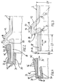
- Fig. 1
- einen Halb-Längsschnitt durch eine erfindungsgemäße Rohrverschraubung im montierten Zustand,
- Fig. 2
- einen Längsschnitt analog zu Fig. 1 des umgeformten Rohrendes mit vormontierter elastischer Dichtung,
- Fig. 3
- eine Schnittdarstellung nur des Rohrendes entsprechend Fig. 2 und
- Fig. 4
- eine Schnittdarstellung der Dichtung entsprechend Fig. 2 in einer lagerichtigen Stellung relativ zu Fig. 3 zur Vormontage auf dem Rohrende durch axiales Aufsetzen.
Claims (10)
- Rohrverschraubung (1) zum Anschluß einer insbesondere metallischen Rohrleitung (2), bestehend aus einem Anschlußstutzen (4) und einem zum Halten der Rohrleitung (2) mit dem Anschlußstutzen (4) verschraubbaren Überwurf-Verschraubungsteil (6), wobei der Anschlußstutzen (4) eine Aufnahmeöffnung (10) für die Rohrleitung (2) mit einer radialen Stufenfläche (12) zur axialen Abstützung der Rohrleitung (2) aufweist, wobei die Rohrleitung (2) einen umfangsgemäßen, durch Stauchumformen gebildeten Ringwulst (14) aufweist, der zur formschlüssigen Halterung der Rohrleitung (2) zwischen dem Anschlußstutzen (4) und dem Verschraubungsteil (6) gehalten ist, und wobei zwischen der Rohrleitung (2) und dem Anschlußstutzen (4) eine elastische Dichtung (16) angeordnet ist,
dadurch gekennzeichnet,
daß die Rohrleitung (2) endseitig derart umgeformt ist, daß ihr freies, sich an den Ringwulst (14) anschließendes, achsparalleles Rohrende (18) einen gegenüber dem ursprünglichen Rohrdurchmesser (D1) reduzierten Enddurchmesser (D2) aufweist, so daß innerhalb der Aufnahmeöffnung (10) des Anschlußstutzens (4) radial zwischen diesem und dem Rohrende (18) eine Dichtungskammer zur Aufnahme der elastischen Dichtung (16) gebildet ist. - Rohrverschraubung nach Anspruch 1 oder nach dem Oberbegriff des Anspruchs 1,
dadurch gekennzeichnet,
daß die Rohrleitung (2) im Bereich des Ringwulstes (14) derart umgeformt ist, daß der Ringwulst (14) auf seiner dem Anschlußstutzen (4) zugekehrten Seite einen Schulterabschnitt (20) mit einem zur Längsachse (22) gemessenen, stumpfen Hinterschneidungswinkel (α) größer 90° aufweist, so daß der Ringwulst (14) an einer radialen Stirnfläche (24) des Anschlußstutzens (4) nur mit einem im wesentlichen linienförmigen Anlagekontaktbereich (26) zur Anlage gelangt. - Rohrverschraubung nach Anspruch 1 oder 2,
dadurch gekennzeichnet,
daß die Dichtung (16) derart ringkappenförmig ausgebildet ist, daß sie auf das freie Rohrende (18) zumindest kraftschlüssig auf setzbar ist und die Rohrwandung axial sowie radial innen und außen umschließt. - Rohrverschraubung nach einem der Ansprüche 1 bis 3,
dadurch gekennzeichnet,
daß der Anschlußstutzen (4) als Normteil mit einem die Aufnahmeöffnung (36) erweiternden Innenkonus (36) ausgebildet ist. - Rohrverschraubung nach einem der Ansprüche 1 bis 4,
dadurch gekennzeichnet,
daß das Verschraubungsteil (6) als Normteil-Überwurfmutter (8) mit einem Innenkonus (38) zur Anlage an dem Ringwulst (14) der Rohrleitung (2) ausgebildet ist. - Rohrverschraubung nach Anspruch 4 oder 5,
dadurch gekennzeichnet,
daß die Dichtung (16) einen entsprechend dem Innenkonus (36) des Anschlußstutzens (4) erweiternd geformten Dichtabschnitt (40) aufweist, der gekammert zwischen dem Anschlußstutzen (4), dem im Durchmesser reduzierten Rohrende (18) und dem Ringwulst (14) unter elastischer Vorspannung angeordnet ist. - Rohrverschraubung nach Anspruch 5 oder 6,
dadurch gekennzeichnet,
daß der Ringwulst (14) der Rohrleitung (2) auf seiner der Überwurfmutter (8) zugekehrten Seite eine Flankenfläche (42) aufweist, die zur flächigen Anlage in dem Innenkonus (38) der Überwurfmutter (8) mit einem entsprechend spitzen Winkel (β) schräg zur Längsachse (22) ausgerichtet ist. - Rohrverschraubung nach einem der Ansprüche 2 bis 7,
dadurch gekennzeichnet,
daß das freie Rohrende (18) ausgehend von der axialen Lage des linienförmigen Anlagekontaktbereiches (26) des Ringwulstes (14) eine Länge (L1) aufweist, die derart kürzer als die zwischen der Stutzen-Stirnfläche (24) und der inneren Stufenfläche (12) gemessene Tiefe (L2) der Aufnahmeöffnung (10) des Anschlußstutzens (4) ist, daß ein axial zwischen der Stufenfläche (12) und dem Rohrende (18) angeordneter Abschnitt (28) der insbeondere ringkappenförmigen Dichtung (16) definiert elastisch verpreßt wird. - Rohrverschraubung nach einem der Ansprüche 1 bis 8,
dadurch gekennzeichnet,
daß der Ringwulst (14) der Rohrleitung (2) in seinem zwischen dem Anschlußstutzen (4) und dem Verschraubungsteil (6) eingespannten Zustand eine Anzugsbegrenzung bewirkt. - Rohrverschraubung nach einem der Ansprüche 1 bis 9,
dadurch gekennzeichnet,
daß die Dichtung (16) als einstückiges Profilformteil aus elastischem Material ausgebildet ist und vorzugsweise auf ihren Dichtflächen in Umfangsrichtung verlaufenden Rillen (46) und/oder Stege (48) zur Bildung von labyrinthdichtungsartigen Zonen aufweist.
Applications Claiming Priority (2)
| Application Number | Priority Date | Filing Date | Title |
|---|---|---|---|
| DE29908670U DE29908670U1 (de) | 1999-05-17 | 1999-05-17 | Rohrverschraubung |
| DE29908670U | 1999-05-17 |
Publications (2)
| Publication Number | Publication Date |
|---|---|
| EP1054203A1 true EP1054203A1 (de) | 2000-11-22 |
| EP1054203B1 EP1054203B1 (de) | 2004-01-21 |
Family
ID=8073624
Family Applications (1)
| Application Number | Title | Priority Date | Filing Date |
|---|---|---|---|
| EP00108764A Expired - Lifetime EP1054203B1 (de) | 1999-05-17 | 2000-04-25 | Rohrverschraubung |
Country Status (2)
| Country | Link |
|---|---|
| EP (1) | EP1054203B1 (de) |
| DE (2) | DE29908670U1 (de) |
Cited By (4)
| Publication number | Priority date | Publication date | Assignee | Title |
|---|---|---|---|---|
| EP1260750A1 (de) | 2001-05-22 | 2002-11-27 | Voss Fluid GmbH + Co. KG | Rohrverschraubung |
| US6883779B2 (en) | 2002-09-09 | 2005-04-26 | Voss Automotive Gmbh | Receiving part of a fluid plug-in coupling |
| WO2008107680A3 (en) * | 2007-03-06 | 2008-10-30 | Corus Uk Ltd | Compression fittings for steel pipes |
| WO2011029687A1 (de) | 2009-09-10 | 2011-03-17 | Voss Fluid Gmbh | Rohrverschraubung und verfahren zur herstellung derselben |
Families Citing this family (1)
| Publication number | Priority date | Publication date | Assignee | Title |
|---|---|---|---|---|
| DE102015122309A1 (de) * | 2015-12-18 | 2017-06-22 | Voss Fluid Gmbh | Rohrverbindung |
Citations (7)
| Publication number | Priority date | Publication date | Assignee | Title |
|---|---|---|---|---|
| FR1257902A (fr) * | 1960-04-12 | 1961-04-07 | Walterscheid Kg Jean | Bague d'étanchéité en métal à déformation plastique |
| US3393930A (en) * | 1966-08-18 | 1968-07-23 | Parker Hannifin Corp | Coupling for thin-walled tubes |
| WO1985002450A1 (en) * | 1983-11-28 | 1985-06-06 | Isadore Pitesky | Coupling |
| DE9320306U1 (de) * | 1993-04-16 | 1994-04-28 | Gkn Walterscheid Gmbh, 53797 Lohmar | Schraubverbindung für Rohre |
| DE19511063A1 (de) | 1994-05-07 | 1995-11-09 | Walterscheid Gmbh Jean | Rohr mit einem Anschlußabschnitt für eine Rohrverbindung und Verfahren zur Herstellung desselben |
| DE19520099A1 (de) | 1995-06-01 | 1997-01-02 | Parker Hannifin Gmbh | Rohrverbindung und Verfahren zu ihrer Herstellung |
| DE29810700U1 (de) | 1998-06-15 | 1999-10-28 | Armaturenfabrik Hermann Voss GmbH + Co, 51688 Wipperfürth | Rohrverschraubung mit Axialdichtung |
-
1999
- 1999-05-17 DE DE29908670U patent/DE29908670U1/de not_active Expired - Lifetime
-
2000
- 2000-04-25 EP EP00108764A patent/EP1054203B1/de not_active Expired - Lifetime
- 2000-04-25 DE DE50005063T patent/DE50005063D1/de not_active Expired - Lifetime
Patent Citations (7)
| Publication number | Priority date | Publication date | Assignee | Title |
|---|---|---|---|---|
| FR1257902A (fr) * | 1960-04-12 | 1961-04-07 | Walterscheid Kg Jean | Bague d'étanchéité en métal à déformation plastique |
| US3393930A (en) * | 1966-08-18 | 1968-07-23 | Parker Hannifin Corp | Coupling for thin-walled tubes |
| WO1985002450A1 (en) * | 1983-11-28 | 1985-06-06 | Isadore Pitesky | Coupling |
| DE9320306U1 (de) * | 1993-04-16 | 1994-04-28 | Gkn Walterscheid Gmbh, 53797 Lohmar | Schraubverbindung für Rohre |
| DE19511063A1 (de) | 1994-05-07 | 1995-11-09 | Walterscheid Gmbh Jean | Rohr mit einem Anschlußabschnitt für eine Rohrverbindung und Verfahren zur Herstellung desselben |
| DE19520099A1 (de) | 1995-06-01 | 1997-01-02 | Parker Hannifin Gmbh | Rohrverbindung und Verfahren zu ihrer Herstellung |
| DE29810700U1 (de) | 1998-06-15 | 1999-10-28 | Armaturenfabrik Hermann Voss GmbH + Co, 51688 Wipperfürth | Rohrverschraubung mit Axialdichtung |
Cited By (8)
| Publication number | Priority date | Publication date | Assignee | Title |
|---|---|---|---|---|
| EP1260750A1 (de) | 2001-05-22 | 2002-11-27 | Voss Fluid GmbH + Co. KG | Rohrverschraubung |
| US7000953B2 (en) | 2001-05-22 | 2006-02-21 | Voss Fluid Gmbh & Co. Kg | Pipe screw-connection |
| US6883779B2 (en) | 2002-09-09 | 2005-04-26 | Voss Automotive Gmbh | Receiving part of a fluid plug-in coupling |
| WO2008107680A3 (en) * | 2007-03-06 | 2008-10-30 | Corus Uk Ltd | Compression fittings for steel pipes |
| GB2447275B (en) * | 2007-03-06 | 2012-01-18 | Caparo Eng Ltd | Compression fittings for steel pipes |
| WO2011029687A1 (de) | 2009-09-10 | 2011-03-17 | Voss Fluid Gmbh | Rohrverschraubung und verfahren zur herstellung derselben |
| DE102009041056A1 (de) | 2009-09-10 | 2011-03-24 | Voss Fluid Gmbh | Rohrverschraubung und Verfahren zur Herstellung derselben |
| US8745869B2 (en) | 2009-09-10 | 2014-06-10 | Voss Fluid Gmbh | Screwed pipe joint and method for the production thereof |
Also Published As
| Publication number | Publication date |
|---|---|
| EP1054203B1 (de) | 2004-01-21 |
| DE50005063D1 (de) | 2004-02-26 |
| DE29908670U1 (de) | 2000-09-21 |
Similar Documents
| Publication | Publication Date | Title |
|---|---|---|
| EP0863354B1 (de) | Rohrverschraubung mit Schneidring für metallische Rohrleitungen | |
| EP1260750B1 (de) | Rohrverschraubung | |
| DE4041679C2 (de) | Rohrverschraubung | |
| EP2872811B1 (de) | Rohrverbindung | |
| DE4041677C2 (de) | Rohrverschraubung mit Schneidring | |
| EP0327080B1 (de) | Rohrklemmverbindung | |
| WO1993025837A1 (de) | Verbindungssystem für rohrleitungen | |
| EP1540234B1 (de) | Adapter-zwischenring für ein einschraubteil eines fluid-stecksystems | |
| DE8807010U1 (de) | Dichtverbindung | |
| DE202007010592U1 (de) | Anordnung zur Befestigung einer Leitung mit einem profilierten Außendurchmesser | |
| EP1054203B1 (de) | Rohrverschraubung | |
| DE29807763U1 (de) | Anschlußvorrichtung zum schnellen und lösbaren Anschluß von Rohrleitungen | |
| EP1086329B1 (de) | Rohrverschraubung mit axialdichtung | |
| DE19855795B4 (de) | Schneidringverschraubung für Druckmittel-Rohrleitungen | |
| DE4319884C2 (de) | Rohrverschraubung mit Schneidring und zusätzlicher Umfangsabdichtung | |
| DE19749142C2 (de) | Absperrarmatur mit einem drehbeweglichen Absperrglied | |
| DE20204506U1 (de) | DKO-Rohrverschraubung | |
| DE102018117593B4 (de) | Schneidringverschraubung | |
| DE4025877C2 (de) | Anschlußvorrichtung für Hydraulik-Rohrleitungen | |
| DE102006023650A1 (de) | Rohrverbindung mit einem umgeformten Rohr | |
| DE19727149C2 (de) | Rohrverschraubung mit Schneidring | |
| DE19512464A1 (de) | Rohrverschraubung mit Axialdichtung | |
| DE19852861C1 (de) | Rohrpreßverbindung | |
| DE4322425A1 (de) | Rohrverschraubung mit Schneidring | |
| DE4042714B4 (de) | Rohrverschraubung mit Schneidring |
Legal Events
| Date | Code | Title | Description |
|---|---|---|---|
| PUAI | Public reference made under article 153(3) epc to a published international application that has entered the european phase |
Free format text: ORIGINAL CODE: 0009012 |
|
| 17P | Request for examination filed |
Effective date: 20000804 |
|
| AK | Designated contracting states |
Kind code of ref document: A1 Designated state(s): DE |
|
| AX | Request for extension of the european patent |
Free format text: AL;LT;LV;MK;RO;SI |
|
| AKX | Designation fees paid |
Free format text: DE |
|
| RAP1 | Party data changed (applicant data changed or rights of an application transferred) |
Owner name: ARMATURENFABRIK HERMANN VOSS GMBH + CO. KG |
|
| 17Q | First examination report despatched |
Effective date: 20020522 |
|
| RAP1 | Party data changed (applicant data changed or rights of an application transferred) |
Owner name: VOSS FLUID GMBH + CO. KG |
|
| GRAH | Despatch of communication of intention to grant a patent |
Free format text: ORIGINAL CODE: EPIDOS IGRA |
|
| GRAS | Grant fee paid |
Free format text: ORIGINAL CODE: EPIDOSNIGR3 |
|
| GRAA | (expected) grant |
Free format text: ORIGINAL CODE: 0009210 |
|
| AK | Designated contracting states |
Kind code of ref document: B1 Designated state(s): DE |
|
| REF | Corresponds to: |
Ref document number: 50005063 Country of ref document: DE Date of ref document: 20040226 Kind code of ref document: P |
|
| PLBE | No opposition filed within time limit |
Free format text: ORIGINAL CODE: 0009261 |
|
| STAA | Information on the status of an ep patent application or granted ep patent |
Free format text: STATUS: NO OPPOSITION FILED WITHIN TIME LIMIT |
|
| 26N | No opposition filed |
Effective date: 20041022 |
|
| PGFP | Annual fee paid to national office [announced via postgrant information from national office to epo] |
Ref country code: DE Payment date: 20100628 Year of fee payment: 11 |
|
| REG | Reference to a national code |
Ref country code: DE Ref legal event code: R119 Ref document number: 50005063 Country of ref document: DE |
|
| REG | Reference to a national code |
Ref country code: DE Ref legal event code: R119 Ref document number: 50005063 Country of ref document: DE |
|
| PG25 | Lapsed in a contracting state [announced via postgrant information from national office to epo] |
Ref country code: DE Free format text: LAPSE BECAUSE OF NON-PAYMENT OF DUE FEES Effective date: 20111031 |