EP1054238A2 - Procédé et appareil de détection de données positionelles utilisant de signaux décalés - Google Patents
Procédé et appareil de détection de données positionelles utilisant de signaux décalés Download PDFInfo
- Publication number
- EP1054238A2 EP1054238A2 EP00110444A EP00110444A EP1054238A2 EP 1054238 A2 EP1054238 A2 EP 1054238A2 EP 00110444 A EP00110444 A EP 00110444A EP 00110444 A EP00110444 A EP 00110444A EP 1054238 A2 EP1054238 A2 EP 1054238A2
- Authority
- EP
- European Patent Office
- Prior art keywords
- detection data
- data
- interpolated
- output signal
- interpolation
- Prior art date
- Legal status (The legal status is an assumption and is not a legal conclusion. Google has not performed a legal analysis and makes no representation as to the accuracy of the status listed.)
- Granted
Links
Images


Classifications
-
- G—PHYSICS
- G01—MEASURING; TESTING
- G01D—MEASURING NOT SPECIALLY ADAPTED FOR A SPECIFIC VARIABLE; ARRANGEMENTS FOR MEASURING TWO OR MORE VARIABLES NOT COVERED IN A SINGLE OTHER SUBCLASS; TARIFF METERING APPARATUS; MEASURING OR TESTING NOT OTHERWISE PROVIDED FOR
- G01D5/00—Mechanical means for transferring the output of a sensing member; Means for converting the output of a sensing member to another variable where the form or nature of the sensing member does not constrain the means for converting; Transducers not specially adapted for a specific variable
- G01D5/12—Mechanical means for transferring the output of a sensing member; Means for converting the output of a sensing member to another variable where the form or nature of the sensing member does not constrain the means for converting; Transducers not specially adapted for a specific variable using electric or magnetic means
- G01D5/14—Mechanical means for transferring the output of a sensing member; Means for converting the output of a sensing member to another variable where the form or nature of the sensing member does not constrain the means for converting; Transducers not specially adapted for a specific variable using electric or magnetic means influencing the magnitude of a current or voltage
- G01D5/20—Mechanical means for transferring the output of a sensing member; Means for converting the output of a sensing member to another variable where the form or nature of the sensing member does not constrain the means for converting; Transducers not specially adapted for a specific variable using electric or magnetic means influencing the magnitude of a current or voltage by varying inductance, e.g. by a movable armature
- G01D5/204—Mechanical means for transferring the output of a sensing member; Means for converting the output of a sensing member to another variable where the form or nature of the sensing member does not constrain the means for converting; Transducers not specially adapted for a specific variable using electric or magnetic means influencing the magnitude of a current or voltage by varying inductance, e.g. by a movable armature by influencing the mutual induction between two or more coils
Definitions
- the present invention relates to a position detection data generating method and apparatus for use in a position detection system which generates a first A.C. output signal having an electrical phase angle shifted in a phase-advancing or positive direction in accordance with a position of an object of detection and a second A.C. output signal having an electrical phase angle shifted in a phase-retreating or negative direction.
- the present invention relates to a technique intended to improve detection performance with respect to dynamic characteristics of an object of detection (i.e., detecting characteristics when the object of detection is changing in position with time); for example, the present invention concerns a technique of detecting a rotational or linear position of an object of detection, such as a rotational position detector like a resolver or synchro or a linear position detector based on a position detecting principle similar to that of the rotational position detector.
- Induction-type rotational position detector apparatus of the type which produces two-phase outputs (i.e., outputs of sine and cosine phases) in response to a single-phase exciting input are commonly known as "resolvers", and induction-type rotational position detector apparatus of the type which produces three-phase outputs (i.e., outputs of three phases shifted from each other by 120°) in response to a single-phase exciting input are commonly known as "synchros".
- a stator includes two-pole (sine and cosine poles) secondary windings that intersect each other at a 90° mechanical angle
- a rotor includes a primary winding (the relationship between the primary and secondary windings may be reversed).
- the resolvers of this type are not satisfactory in that they need a brush to electrically contact the primary winding of the rotor.
- the assignee of the instant application has recently developed an apparatus which, using a variable-reluctance-type detector having windings provided only on the stator (or the rotor), generates two-phase outputs (sine-phase and cosine-phase outputs) in response to a single-phase exciting input.
- the position detector apparatus which produce two-phase outputs (i.e., outputs of sine and cosine phases) in response to a single-phase exciting input as mentioned above have been proposed not only for the rotary position detection but also for the linear position detection.
- phase difference detection technique suitably applicable to the so-called resolver-type position detector apparatus producing two-phase outputs in response to a single-phase exciting input.
- This proposed phase difference detection technique gives a solution to the problem that A.C. signals induced in secondary windings would vary subtly in electric phase, in response to an ambient temperature change, to cause a detection error because the windings (coils) of the position detector apparatus vary in their impedance due to the ambient temperature change.
- the proposed phase difference detection technique generally comprises the following steps.
- phase angle ⁇ corresponding thereto would also vary over time, although no significant problem occurs when the position-to-be-detected is not moving.
- the phase difference amount ⁇ of the A.C. output signals sin( ⁇ t ⁇ d+ ⁇ ) and sin( ⁇ t ⁇ d- ⁇ ) would present, rather than a constant value, dynamic characteristics time-varying in correspondence with a moving speed of the object of detection. If the time-varying dynamic characteristics are represented collectively by ⁇ (t), then the A.C. output signals can be expressed by sin ⁇ t ⁇ d+ ⁇ (t) ⁇ and sin ⁇ t ⁇ d- ⁇ (t) ⁇ , respectively.
- the leading-phase A.C. output signal shifts to a higher frequency in accordance with the dynamic characteristics + ⁇ (t), while the trailing-phase A.C. output signal shifts to a lower frequency in accordance with the dynamic characteristics - ⁇ (t).
- the cycles of the two A.C. output signals sequentially shift in the opposite directions per cycle of the reference signal sin ⁇ t , which would make it difficult to accurately calculate the phase variation error ⁇ d by only performing the arithmetic operation of Step 3 above.
- the above-discussed prior phase difference detection technique is arranged to detect when there occurs a coincidence in zero cross between the two A.C. output signals sin ⁇ t ⁇ d+ ⁇ (t) ⁇ and sin ⁇ t ⁇ d- ⁇ (t) ⁇ . More specifically, each time such a coincidence in zero cross between the two A.C. output signals is detected, the phase detection data of either one of the A.C. output signals sin ⁇ t ⁇ d+ ⁇ (t) ⁇ and sin ⁇ t ⁇ d- ⁇ (t) ⁇ relative to the predetermined reference A.C. signal sin ⁇ t is held as the error data ⁇ d, and then the position detection data is modified at Step 4 above using the thus-held error data.
- phase detection data can be obtained only when the zero crosses of the A.C. output signals sin( ⁇ t+ ⁇ ) sin( ⁇ t- ⁇ ) coincide with each other
- the above-discussed prior phase difference detection technique faces the serious problem that the timewise detecting resolution of the phase detection data is limited to just one cyclic period of the A.C. signals and thus the response performance with respect to the dynamic characteristics (i.e., detecting characteristics when the position-to-be-detected is changing over time) is limited to a significant degree.
- the response capability can be even further degraded because the detection of the error data ⁇ d taking the dynamic characteristics into account requires waiting for time points when a coincidence in zero cross occurs between the two A.C. output signals.
- the present invention provides a position detection data generating method for use in a position detection system that produces a first A.C. output signal having an electric phase angle shifted in a positive direction in accordance with a position-to-be-detected and a second A.C. output signal having an electric phase angle shifted in a negative direction, which method comprises: a first step of generating first detection data by detecting a phase difference of the first A.C. output signal from a predetermined reference phase and generating second detection data by detecting a phase difference of the second A.C.
- the above-mentioned fifth step includes a step of obtaining error data contained in the first and second detection data by performing an arithmetic operation between the first and second interpolated detection data provided by the fourth step, and a step of providing interpolated position detection data indicative of the position-to-be-detected by performing an arithmetic operation to remove the error data from one of the first and second interpolated detection data.
- the present invention can improve its response performance with respect to dynamic characteristics (detecting characteristics when the position-to-be-detected is changing over time) by generating the first and second interpolated detection data, densely at close time intervals, through the predictive interpolation operation.
- the timewise density or precision of the first and second interpolated detection data can be increased significantly, which allows the error data to be calculated whenever necessary by the fifth step and which therefore can eliminate the need to wait for a time point where a coincidence in zero cross occurs between the two A.C. output signals as in the conventionally-known techniques; therefore, the present invention achieves an improved response capability or responsivity.
- the present invention can appropriately correct an error that is likely to occur in the interpolating arithmetic operation due to a possible difference in linearity of frequency transition (cyclic period transition) caused by the Doppler effect between the signals phase-shifted in the positive and negative directions. As a consequence, the present invention can perform the interpolating arithmetic operation with increased accuracy.
- the present invention also provides a position detection data generating method for use in a position detection system that produces a first A.C. output signal having an electric phase angle shifted in a positive direction in accordance with a position-to-be-detected and a second A.C. output signal having an electric phase angle shifted in a negative direction, which method comprises: a first step of generating first detection data by detecting a phase difference of the first A.C. output signal from a predetermined reference phase and generating second detection data by detecting a phase difference of the second A.C.
- the response performance with respect to dynamic characteristics can be significantly improved by generating the first and second interpolated detection data, densely at close time intervals, through the predictive interpolation.
- the timewise density or precision of the first and second interpolated detection data can be increased, which allows the error data to be calculated whenever necessary by the fourth step and which therefore can eliminate the need to wait for a time point where a coincidence in zero cross occurs between the two A.C. output signals as in the conventionally-known techniques; as a consequence, the present invention achieves an improved response capability.
- the present invention provides a position detection data generating method for use in a position detection system which produces a first A.C. output signal having an electric phase angle shifted in a positive direction in accordance with a position-to-be-detected and a second A.C. output signal having an electric phase angle shifted in a negative direction, which comprises: a first step of generating first detection data by detecting a phase difference of the first A.C. output signal from a predetermined reference phase and generating second detection data by detecting a phase difference of the second A.C.
- the response performance with respect to dynamic characteristics can be significantly improved by generating the first and second interpolated detection data, densely at close time intervals, through the predictive interpolation.
- the timewise density or precision of the first and second interpolated detection data can be increased, which allows the error data to be calculated whenever necessary by the third step and which therefore can eliminate the need to wait for a time point where a coincidence in zero cross occurs between the two A.C. output signals as in the conventionally-known techniques; as a consequence, the present invention achieves an improved response capability.
- the present invention may be constructed and implemented not only as the method invention as set out above but also as a system or apparatus invention.
- the present invention may also be practiced as a program for execution by a processor such as a computer or DSP, or a storage medium storing such a program.
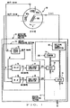
- Fig. 1 is a block diagram showing a general organization of a position detection system employing a position detection data generating method in accordance with a preferred embodiment of the present invention.
- This position detection system generally comprises a position sensor 10 and a detection processing unit 11, and the detection processing unit 11 includes an analog processing section 12 and a digital processing section 13 as will be later described in detail.
- Various components characterizing the inventive position detection data generating method are contained in the digital processing section 13.
- Fig. 1 shows only a part of the inner structure of the digital processing section 13, details of which are shown in Fig. 2.
- the position sensor 10 and analog processing section 12 cooperate with each other to produce a first A.C. output signal (for convenience, denoted by “ sin( ⁇ t+ ⁇ ) ”) having an electric phase angle (denoted by "+ ⁇ ") shifted in a phase-advancing or positive direction in accordance with a position of an object of detection (i.e., a position-to-be-detected) and a second A.C. output signal (for convenience, denoted by “ sin( ⁇ t- ⁇ ) " having an electric phase angle ("- ⁇ ") shifted in a phase-retreating or negative direction in accordance with the position-to-be-detected.
- the position sensor 10 and analog processing section 12 may be constructed in any other manner than that shown in Fig. 1 as long as they can produce such two different A.C. output signals. The following paragraphs describe exemplary structural arrangements for producing the above-mentioned two different A.C. output signals.
- the position sensor 10 may be of any type, such as a conventionally-known brushless or brush-equipped resolver.
- the position sensor 10 may be a variable-reluctance type position sensor where primary and secondary windings are provided on the stator with no winding provided on the rotor or movable member, and the position sensor 10 may be either a rotational position detecting sensor or linear position detecting sensor.
- a single-phase exciting A.C. signal EAC generated by the detection processing section 11 is applied to the position sensor 10 so as to excite the primary winding W1.
- a counter 19 counts predetermined high-speed clock pulses CK
- an exciting signal generation circuit 20 generates an exciting A.C. signal on the basis of a counted value of the counter 19, and the generated exciting A.C. signal is supplied to the primary winding W1 of the position sensor 10.
- the modulus or modulo number of the counter 19 corresponds to one cycle of the exciting A.C. signal EAC, and it is assumed herein, for convenience of description, that a counted value "0" of the counter 19 corresponds to a zero phase of a predetermined reference A.C. signal sin ⁇ t .
- each exciting A.C. signal EAC is generated, by the exciting signal generation circuit 20, in correspondence with the reference A.C. signal sin ⁇ t .
- the first and second A.C. output signals A and B produced by the position sensor 10 are first supplied to the analog processing section 12 of the detection processing section 11.
- the above-mentioned output signals Y1 and Y2 from the adder and subtracter circuits 15 and 16 are given to zero-cross detection circuits 17 and 18 for detection of the respective zero-cross points of the first and second signals Y1 and Y2.
- the zero-cross detection may be done by, for example, identifying a point where each of the signal Y1, Y2 changes from a negative polarity to a positive polarity, i.e., a zero phase point.
- Zero-cross detection pulses generated by the circuits 17 and 18 upon detection of the respective zero-cross points are applied as latch pulses LP1 and LP2 to the digital processing section 13 for purposes to be described below.
- the latch pulse LP1 corresponding to the electric phase shifted in the positive direction in correspondence to the position-to-be-detected x i.e., the leading phase + ⁇
- the latch pulse LP2 corresponding to the electric phase shifted in the negative direction in correspondence to the position-to-be-detected x i.e., the trailing phase - ⁇
- each of the latches 21 and 31 latches a current count of the counter 19 at generation timing of the corresponding latch pulse LP1 or LP2.
- data P 1 and M 1 latched in the latches 21 and 31 correspond to the phase differences of the output signals Y1 and Y2 (+ ⁇ and - ⁇ ) from the reference A.C. signal sin ⁇ t .
- the operation for latching the data P 1 and M 1 in the latches 21 and 31 in response to the respective latch pulses LP1 and LP2 constitutes a process for generating first detection data P 1 by detecting a phase difference of the first A.C. output signal " sin( ⁇ t+ ⁇ ) " having its electric phase angle ("+ ⁇ ") shifted in the positive direction in accordance with the position-to-be-detected x and generating second detection data M 1 by detecting a phase difference of the second A.C. output signal " sin( ⁇ t- ⁇ ) " having its electric phase angle ("- ⁇ ") shifted in the negative direction in accordance with the position-to-be-detected x.
- phase variation error of the output signal which may result from influences of a length of a cable connecting between the position sensor 10 and the detection processing section 11 and impedance variations, due to an ambient temperature change, of the windings W1, W2s and W2c in the position sensor 10, is represented collectively by " ⁇ d"
- each of the detection data P 1 and M 1 would inevitably contain such an error ⁇ d and thus does not indicates an actual phase angle corresponding exactly to the position-to-be-detected x; the error ⁇ d is contained in each of the detection data P 1 and M 1 as an error in the same (phase) direction as illustratively shown in Figs. 3A and 3B.
- Fig. 3A shows an example where the phase error ⁇ d is a positive phase error (+d)
- Fig. 3B shows an example where the phase error ⁇ d is a negative phase error (-d).
- the detection data P 1 of the leading phase presents a phase difference of " ⁇ d+ ⁇ " from a reference phase R0 (e.g., the zero phase of the reference A.C. signal sin ⁇ t ), and the detection data M 1 of the trailing phase presents a phase difference of " ⁇ d- ⁇ " from the reference phase R0.
- a reference phase R0 e.g., the zero phase of the reference A.C. signal sin ⁇ t
- the detection data M 1 of the trailing phase presents a phase difference of " ⁇ d- ⁇ " from the reference phase R0.
- each of the latches 21 and 31 latches the count of the same counter 19; thus, if the count of the counter 19 is regarded directly as an absolute value of the trailing phase - ⁇ , the latch 21 for the leading phase + ⁇ will latch phase data corresponding to a complement of 360° (i.e., "360°- ⁇ "). This is equivalent to latching data, corresponding to the signed phase differences "+ ⁇ " and "- ⁇ ", in the latches 21 and 31 directly as the detection data P 1 and M 1 .
- the detection data P 1 and M 1 are assumed to correspond to the signed phase differences "+ ⁇ " and "- ⁇ ” like this, dividing, by two, the sum of the two detection data P 1 and M 1 of the leading and trailing phases as above can correspond to detecting the error ⁇ d.
- the absolute value " ⁇ " of the leading phase may be latched in the latch 21; for that purpose, the count of the counter 19 may be latched in the latch 31 directly, and a negative value of the count of the counter 19 or a complement of the count relative to the modulo number (a difference between the maximum count and the current count) may be latched in the other latch 21.
- the detection data P 1 pertaining to the leading phase "+ ⁇ " latched in the latch 21 represents the absolute value of the difference ⁇
- the detection data M 1 pertaining to the trailing phase "- ⁇ " latched in the latch 31 represents the absolute value of the difference ⁇
- the error ⁇ d can be identified by dividing, by two, a difference between the detection data P 1 indicative of the absolute value " ⁇ d” of the leading phase " ⁇ d+ ⁇ ” containing the error ⁇ d” and the detection data M 1 indicative of the absolute value " ⁇ -( ⁇ d)" of the trailing phase " ⁇ d- ⁇ " containing the error " ⁇ d". Details of the data format and arithmetic operations may be modified as appropriate.
- secondary latches (i.e., registers) 22 and 32 are provided in corresponding relation to the primary latches 21 and 31.
- the output from the primary latch 21 is latched (i.e., shifted) into the corresponding secondary latch 22 in accordance with the latch pulse LP1
- the output from the primary latch 31 is latched (i.e., shifted) into the corresponding secondary latch 32 in accordance with the latch pulse LP2.
- the data latched in the latch 21 (or 31) at the generation timing of the preceding latch pulse LP1 (or LP2) i.e., preceding sample of phase difference detection data immediately preceding the current sample
- the secondary latch 22 (or 32) is transferred to the secondary latch 22 (or 32) .
- the data latched in the primary latch 21 (or 31) and then output therefrom in response to the currently generated latch pulse LP1 (or LP2) is assumed to be the current sample of the phase difference detection data P 1 (or M 1 )
- the data transferred to and output from the secondary latch 22 (or 32) at that time can be said to be the last or preceding sample of the phase difference detection data P 0 (or M 0 ).
- two successive samples P 1 and P 0 of the first detection data P 1 having a tendency to phase-shift in the positive direction, i.e., of the leading phase are obtained from the primary and secondary latches 21 and 22.
- two successive samples M 1 and M 0 of the second detection data M 1 having a tendency to phase-shift in the negative direction, i.e., of the trailing phase are obtained from the primary and secondary latches 31 and 32.
- one sample cycle is one alternating cycle of the first A.C. output signal sin( ⁇ t+ ⁇ ) , which corresponds to one cycle of the reference A.C. signal sin ⁇ t when the position-to-be-detection is not moving or stationary but shifts in the positive direction (i.e., in a direction where the alternating period gets shorter) when the position-to-be-detection is moving. This is because the latch timing gets faster every sample cycle.
- one sample cycle is one alternating cycle of the second A.C. output signal sin( ⁇ t- ⁇ ) , which corresponds to one cycle of the reference A.C. signal sin ⁇ t when the position-to-be-detection is not moving but shifts in the negative direction (i.e., in a direction where the alternating period gets longer) when the position-to-be-detection is moving. This is because the latch timing gets slower every sample cycle.
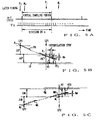
- 3C shows exemplary phase differences of various samples of the phase difference detection data P 0 , P 1 , M 0 , M 1 from the reference phase R0 and thereby graphically illustrates the variation amounts ⁇ P and ⁇ M of the leading and trailing phases per sample cycle.
- the variation amounts ⁇ P and ⁇ M in the different directions are used in subsequent interpolating arithmetic operations as predicted values of variation amounts till the respective next latch timing.
- an adder 24 adds together the current sample of the detection data P 1 output from the latch 21 and the predicted variation amount ⁇ P to be used till the next sample timing output from the subtracter 23, to thereby obtain a target value TP for the interpolating arithmetic operations.
- an adder 34 adds together the current sample of the detection data M 1 output from the latch 31 and the predicted variation amount ⁇ M to be used till the next sample timing output from the subtracter 33, to thereby obtain a target value TM for the interpolating arithmetic operations.
- the target values TP and TM are not definite targets for the interpolating arithmetic operations and merely used as guidelines indicating approximate courses of the interpolation. What actually concerns the determination of specific interpolation values is a standard predicted value as will be stated below.
- phase variation amount ⁇ P in the phase-advancing or positive direction (or timewise compressing direction) and the phase variation amount ⁇ M in the phase-retreating or negative direction (or timewise stretching direction) would occur due to the Doppler effect and depends on a moving speed of the object of detection (or the number of rotations if the object of detection is a rotating member).
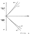
- phase variation amounts ⁇ P and ⁇ M in the positive and negative directions present a nonlinear characteristic relative to the moving speed rather than a linear characteristic as illustratively shown in Fig. 4.
- the instant embodiment is arranged to avoid such an error by correcting the nonlinear characteristics of these variation amounts ⁇ P and ⁇ M (namely, primary predicted values).
- a value obtained by correcting the nonlinear characteristics of these variation amounts ⁇ P and ⁇ M will be called a "standard predicted value" (normalized predicted value).
- the modified predicted value i.e. standard predicted value VT
- VT (
- the standard predicted value VT presents a generally linear characteristic relative to the moving speed of the object of detection, as denoted by broken line in Fig. 4.
- the standard predicted value VT corresponds to variation amounts, i.e. predicted values, between samples that will be obtained by sampling (or latching) the detection data P 1 and M 1 of the leading and trailing phases in a predetermined standard sampling period (one period of the reference A.C.
- the standard predicted value VT when used in arithmetic operators 25 and 35 at later steps, plus and minus signs corresponding to the positive and negative inclinations of the individual predicted values ⁇ P and ⁇ M are attached to the standard predicted value VT.
- the minus sign is attached to the standard predicted value VT to be used in the arithmetic operator 25 for the leading phase because the predicted value ⁇ P of the leading phase has a negative inclination as denoted by broken line VT'.
- the standard predicted value may be determined in any other suitable manner than the above-mentioned; for example, nonlinearity conversion tables of opposite characteristics may be used for the leading and trailing phases to convert the respective predicted values ⁇ P and ⁇ M into values presenting predetermined linear characteristics, in which case the standard predicted value is generated separately for each of the leading and trailing phases.
- the first-mentioned manner of determining the standard predicted value based on calculation of the average value is very advantageous over the second-mentioned manner of using the conversion tables in that it requires only very simple arrangements.
- the predicted values ⁇ P and ⁇ M may each be determined on the basis of a difference between two samples of the phase detection data apart from each other by more than one sample (variation amount over two or more sample cycles) rather than two successive or adjoining samples (variation amount in just one sample cycle). Further, the predicted values ⁇ P and ⁇ M may each be determined on the basis of a difference between three or more samples of the phase detection data rather than two samples.
- the interpolating arithmetic operations are carried out on the basis of the above-mentioned virtual sampling (latching) period, i.e. the predetermined standard sampling period (one period or cycle of the reference A.C. signal sin ⁇ t ).
- the predetermined standard sampling period one period or cycle of the reference A.C. signal sin ⁇ t .
- one period of the exciting reference A.C. signal sin ⁇ t e.g., 100 ⁇ s where the reference A.C. signal is at a 10 kHz frequency
- n a predetermined value
- the arithmetic operator 25 calculates an interpolation value (i.e., interpolation increment) AP per interpolation step, using at least the standard predicted value VT determined via the arithmetic operator 30.
- the interpolation value or increment AP per interpolation step can be determined by dividing, by the number of the interpolation steps, the standard predicted value VT representing the variation amount per virtual sampling period.
- the immediately preceding interpolation value interpolated result, i.e.
- the arithmetic operator 25 calculates every new interpolation increment AP by performing the following arithmetic operation using the currently-sampled new detection data P 1 output from the latch 21 and a latest interpolation value (interpolated result, i.e. interpolated detection data) PA obtained via an interpolation processing section 26.
- (P 1 - PA) represents a difference between the current interpolated detection data, i.e. latest interpolation value, PA and the currently-sampled new detection data P 1 .
- the standard predicted value for the next virtual sampling period is modified by adding the error to the standard predicted value VT and the thus-modified standard predicted value is divided by "n", to thereby determine the interpolation increment Ap.
- the variation amount ⁇ P has a negative inclination
- the negative form of the value determined via the arithmetic operator 30 i.e., VT' of Fig. 4
- the interpolation increment Ap becomes a negative value (and hence a decrement).
- the arithmetic operator 35 calculates every new interpolation increment Am by performing, at the generation timing of the latch pulse LP2, the following arithmetic operation using the standard predicted value VT, above-mentioned dividing number or divisor n, currently-sampled new detection data M 1 output from the latch 31 and latest interpolation value (interpolated result, i.e. interpolated detection data) MA obtained via an interpolation processing section 36.
- Am ⁇ (M 1 - MA) + VT ⁇ ⁇ n
- "(M 1 - MA)" represents a difference between the current interpolated detection data, i.e.
- the standard predicted value for the next virtual sampling period is modified by adding the error to the standard predicted value VT and the thus-modified standard predicted value is divided by "n", to thereby determine the interpolation increment Am.
- the variation amount ⁇ M determined via the arithmetic operator 33 has a positive inclination
- the value determined via the arithmetic operator 30 is given directly (with the positive sign unchanged) as the standard predicted value VT to be used in the above-mentioned arithmetic operation by the arithmetic operator 35.
- the interpolation increment Ap calculated by the arithmetic operator 25 is cumulatively added to the latest interpolation value PA every interpolation step based on the interpolation clock pulse Tn.
- the interpolation processing section 26 carries out the predictive interpolating arithmetic operations sequentially in accordance with the passage of time. More specifically, every interpolation step based on the interpolation clock pulse Tn, the interpolation processing section 26 goes to step 26a where it adds the interpolation increment 26a to the current interpolated detection data, i.e. latest interpolation value, PA to thereby update the interpolated detection data or latest interpolation value PA.
- next step 26b it is ascertained whether or not the value of the interpolated detection data PA has reached or exceeded the target value TP. If answered in the negative at step 26b, the interpolation processing section 26 reverts to step 26a in order to perform a further cumulative addition of the interpolation increment Ap to the interpolated detection data PA. In this way, the interpolation processing section 26 cumulatively adds the interpolation increment Ap to the latest interpolation value PA every interpolation step. Once the value of the interpolated detection data PA has reached or exceeded the target value TP, an YES determination is made at step 26b, so that the cumulative addition of the interpolation increment Ap at step 26a is temporarily stopped.
- step 26a makes a determination as to whether a relationship of "PA ⁇ TP" has been established or not.
- the interpolation increment Am calculated by the arithmetic operator 35 is cumulatively added, at step 36a, to the latest interpolation value MA every interpolation step based on the interpolation clock pulse Tn, so as to carry out the predictive interpolating arithmetic operations sequentially in accordance with the passage of time.
- the interpolated detection data MA determined by the arithmetic operation of step 36a is latched into an interpolated output latch 37 per interpolation step in response to the interpolation clock pulse Tn. If the interpolation increment Am is a positive value, the value of the interpolated detection data MA obtained by the addition of step 36b increases gradually, so that there are obtained, through the predictive interpolating arithmetic operations, interpolated detection data MA shifting minutely in the negative direction. Because, in this case, the target value TM is greater than the last-obtained latest interpolation value MA, step 36b makes a determination as to whether a relationship of "MA ⁇ TM" has been established or not.
- Fig. 5B is a diagram explanatory of an example of the interpolating arithmetic operations in the phase-advancing or positive direction.
- a difference between the latest interpolation value PA' and the currently-sampled detection data P 1 detected at the generation timing of the latch pulse LP1 is added to the standard predicted value VT so that the standard predicted value VT is modified as denoted by VT1.
- the interpolation increment (decrement) Ap is calculated on the basis of the modified standard predicted value, and interpolated detection data PA is obtained by cumulatively adding the interpolation increment (decrement) Ap to the latest interpolated PA' every interpolation step.
- Fig. 5C is a diagram explanatory of an example of the interpolating arithmetic operations in the phase-retreating or negative direction.
- a difference between the latest interpolation value MA' and the currently-sampled detection data M 1 detected at the generation timing of the latch pulse LP2 is added to the standard predicted value VT so that the standard predicted value VT is modified as denoted by VT2.
- the interpolation increment Am is calculated on the basis of the modified standard predicted value, and interpolated detection data MA is obtained by cumulatively adding the interpolation increment Am to the latest interpolated MA' every interpolation step.
- the interpolated detection data PA and MA in the phase-advancing and phase-retreating directions, output from the interpolated output latches 27 and 37, are passed to an arithmetic operator 28, where an arithmetic operation is performed to eliminate the above-mentioned error ⁇ d in a temperature characteristic change or the like. Namely, just as the error ⁇ d can be detected by adding together the two detection data P 1 and M 1 of the leading and trailing phases and dividing, by two, the sum of the detection data P 1 and M 1 as described earlier in relation to Figs.
- the arithmetic operator 28 can accurately detect the error ⁇ d caused by an impedance variation resulting from a temperature characteristic change or the like even when the position-to-be-detected is moving, i.e., when the component + ⁇ and - ⁇ vary over time as + ⁇ (t) and - ⁇ (t).
- Arithmetic operator 29 subtracts the error ⁇ d determined by the operator 28 from one of the interpolated detection data of the leading and trailing phases PA or MA (PA in the illustrated example), so as to provide accurate (error-free) position detection data P from which the error ⁇ d has been removed and which has undergone a dynamic-characteristic-compensating interpolation.
- P PA - ( ⁇ d)
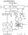
- interpolating arithmetic operations in the instant embodiment may be performed in accordance with any other algorithm than the above-mentioned as exemplarily shown in Fig. 6.
- a group of latches (or registers) 40 is similar to the latches 21, 22, 31 and 33 of Fig. 2, which latch the count outputs from the counter 19 in response to the latch pulses LP1 and LP2 and sequentially shift and hold the count outputs to thereby generate a plurality of samples of phase different detection data P 0 , P 1 , M 0 and M 1 in the phase-advancing and phase-retreating directions.
- the preferred embodiment has been described above as obtaining interpolated position data P for the detection data of the leading phase, it should be obvious that the present invention can obtain interpolated position data M of the trailing phase, in which case the interpolating arithmetic operator 47 operates, in response to the latch pulse LP2, to generate an interpolation value qAm by accumulating an interpolation increment Am.
- circuits employed in the preferred embodiment may comprise integrated circuitry including logical operator elements, gate array etc. rather than discrete circuits, or circuitry using a digital signal processor operating by microprograms, or any other suitable high-density integrated circuitry. Further, they may be implemented by a software program using a CPU and the like. All of such embodiments are embraced in the scope of the present invention. Particularly, the digital processing section 13 of Fig. 2 can be suitably implemented using a program-based processor such as a CPU.
- the apparatus or system may additionally include a function of extracting the output data ⁇ d from the arithmetic operator 28 or 41 as ambient-temperature detection data.
- the present invention can improve its response performance with respect to dynamic characteristics (detecting characteristic when the position-to-be-detected is changing over time) by generating the first and second interpolated detection data of the leading and trailing phases, densely at close time intervals, through the predictive interpolation.
- the timewise density or precision of the first and second interpolated detection data can be increased significantly, which can therefore eliminate the need to wait for time points where a coincidence in zero cross occurs between the two A.C. output signals as in the conventionally-known techniques and which thereby achieves an improved response capability.
- the present invention can appropriately correct an error that is likely to occur in the interpolating arithmetic operations due to a possible difference in linearity of frequency transition (cyclic period transition) between the signals phase-shifted in the positive and negative directions (i.e., the signals of the leading and trailing phases), and thereby can perform the interpolating arithmetic operations with increased accuracy.
Landscapes
- Physics & Mathematics (AREA)
- General Physics & Mathematics (AREA)
- Transmission And Conversion Of Sensor Element Output (AREA)
- Measurement Of Length, Angles, Or The Like Using Electric Or Magnetic Means (AREA)
- Measurement Of Velocity Or Position Using Acoustic Or Ultrasonic Waves (AREA)
- Radar Systems Or Details Thereof (AREA)
Applications Claiming Priority (2)
| Application Number | Priority Date | Filing Date | Title |
|---|---|---|---|
| JP13924299 | 1999-05-19 | ||
| JP13924299A JP4355395B2 (ja) | 1999-05-19 | 1999-05-19 | 位置検出データ生成方法及び装置 |
Publications (3)
| Publication Number | Publication Date |
|---|---|
| EP1054238A2 true EP1054238A2 (fr) | 2000-11-22 |
| EP1054238A3 EP1054238A3 (fr) | 2002-03-27 |
| EP1054238B1 EP1054238B1 (fr) | 2017-07-12 |
Family
ID=15240779
Family Applications (1)
| Application Number | Title | Priority Date | Filing Date |
|---|---|---|---|
| EP00110444.7A Expired - Lifetime EP1054238B1 (fr) | 1999-05-19 | 2000-05-16 | Procédé et appareil de détection de données positionelles utilisant de signaux décalés |
Country Status (3)
| Country | Link |
|---|---|
| US (2) | US6484120B1 (fr) |
| EP (1) | EP1054238B1 (fr) |
| JP (1) | JP4355395B2 (fr) |
Cited By (3)
| Publication number | Priority date | Publication date | Assignee | Title |
|---|---|---|---|---|
| WO2003100353A1 (fr) * | 2002-05-29 | 2003-12-04 | Toyoda Koki Kabushiki Kaisha | Detecteur d'angle de rotation et son procede de correction de temperature |
| EP2833100A3 (fr) * | 2013-08-02 | 2015-08-05 | Hahn-Schickard-Gesellschaft für angewandte Forschung e.V. | Capteur destiné à afficher une position ou une modification de position d'un éléments de couplage et procédé de fonctionnement du capteur |
| US9581425B2 (en) | 2013-08-02 | 2017-02-28 | Hahn-Schickard-Gesellschaft für angewandte Forschung e.V. | Sensor for indicating a position or a change in position of a coupling element and method for operating the sensor |
Families Citing this family (7)
| Publication number | Priority date | Publication date | Assignee | Title |
|---|---|---|---|---|
| DE10132685A1 (de) * | 2001-07-05 | 2003-01-16 | Bosch Gmbh Robert | Verfahren und Vorrichtung zur Bestimmung eines Drehwinkels oder Weges |
| JP2005037305A (ja) * | 2003-07-17 | 2005-02-10 | Sanyo Denki Co Ltd | レゾルバの検出位置補正方法及び装置 |
| US7456629B2 (en) * | 2006-07-11 | 2008-11-25 | Continental Automotive Systems Us, Inc. | Rotary angle sensing system |
| US7977936B2 (en) * | 2008-10-16 | 2011-07-12 | Hamilton Sundstrand Corporation | Resolver interface and signal conditioner |
| DE102009005494A1 (de) * | 2009-01-21 | 2010-07-22 | Kuka Roboter Gmbh | Verfahren und Vorrichtung zur Bestimmung einer Winkellage mittels eines Resolvers |
| US9225225B2 (en) * | 2013-08-02 | 2015-12-29 | Hamilton Sundstrand Corporation | Sensing PM electrical machine position |
| US10250456B2 (en) * | 2016-05-17 | 2019-04-02 | Microsoft Technology Licensing, Llc | Operational management in cloud computing systems |
Family Cites Families (3)
| Publication number | Priority date | Publication date | Assignee | Title |
|---|---|---|---|---|
| JPH07336979A (ja) * | 1994-06-06 | 1995-12-22 | Nippon Seiko Kk | 位置検出方法及び位置検出装置 |
| DE19536661A1 (de) * | 1995-09-30 | 1997-04-03 | Heidenhain Gmbh Dr Johannes | Magnetische Positionsmeßeinrichtung |
| US5710509A (en) * | 1995-10-30 | 1998-01-20 | Atsutoshi Goto | Phase difference detection device for an inductive position detector |
-
1999
- 1999-05-19 JP JP13924299A patent/JP4355395B2/ja not_active Expired - Lifetime
-
2000
- 2000-05-16 EP EP00110444.7A patent/EP1054238B1/fr not_active Expired - Lifetime
- 2000-05-18 US US09/574,163 patent/US6484120B1/en not_active Expired - Lifetime
-
2002
- 2002-09-25 US US10/254,404 patent/US6571194B2/en not_active Expired - Lifetime
Cited By (4)
| Publication number | Priority date | Publication date | Assignee | Title |
|---|---|---|---|---|
| WO2003100353A1 (fr) * | 2002-05-29 | 2003-12-04 | Toyoda Koki Kabushiki Kaisha | Detecteur d'angle de rotation et son procede de correction de temperature |
| US7138795B2 (en) | 2002-05-29 | 2006-11-21 | Toyoda Koki Kabushiki Kaisha | Rotation angle detector and its temperature correcting method |
| EP2833100A3 (fr) * | 2013-08-02 | 2015-08-05 | Hahn-Schickard-Gesellschaft für angewandte Forschung e.V. | Capteur destiné à afficher une position ou une modification de position d'un éléments de couplage et procédé de fonctionnement du capteur |
| US9581425B2 (en) | 2013-08-02 | 2017-02-28 | Hahn-Schickard-Gesellschaft für angewandte Forschung e.V. | Sensor for indicating a position or a change in position of a coupling element and method for operating the sensor |
Also Published As
| Publication number | Publication date |
|---|---|
| JP4355395B2 (ja) | 2009-10-28 |
| EP1054238B1 (fr) | 2017-07-12 |
| US20030033103A1 (en) | 2003-02-13 |
| US6484120B1 (en) | 2002-11-19 |
| JP2000329505A (ja) | 2000-11-30 |
| EP1054238A3 (fr) | 2002-03-27 |
| US6571194B2 (en) | 2003-05-27 |
Similar Documents
| Publication | Publication Date | Title |
|---|---|---|
| US5710509A (en) | Phase difference detection device for an inductive position detector | |
| US7895010B2 (en) | Resolver angle detection device and method of detecting position with a resolver | |
| EP1046884B1 (fr) | Capteur de position | |
| JP5173962B2 (ja) | レゾルバ/デジタル変換装置およびレゾルバ/デジタル変換方法 | |
| EP0874223A1 (fr) | Circuit d'interpolation de codeur | |
| US20030076060A1 (en) | Method and apparatus for calibrating and initializing an electronically commutated motor | |
| JPWO2000028283A1 (ja) | 位置検出装置 | |
| US7088025B2 (en) | Variable-reluctance resolver and rotational angle sensor using same | |
| JPH06167354A (ja) | スケールの内挿処理装置 | |
| JPH0373808B2 (fr) | ||
| EP1054238B1 (fr) | Procédé et appareil de détection de données positionelles utilisant de signaux décalés | |
| US6552666B1 (en) | Phase difference detection device and method for a position detector | |
| JP3372450B2 (ja) | エンコーダの出力信号処理装置 | |
| KR101175962B1 (ko) | 리졸버를 이용해 각위치를 결정하기 위한 방법 및 장치 | |
| JP3665733B2 (ja) | レゾルバの位相誤差補正方法及び装置 | |
| US8278915B2 (en) | Minimizing magnetic interference in a variable reluctance resolver | |
| JP4662516B2 (ja) | 位置検出装置 | |
| JP2009288241A6 (ja) | 第1の事象と第2の事象との間の時間差を求める方法 | |
| JP2009288241A (ja) | 第1の事象と第2の事象との間の時間差を求める方法 | |
| JPH1019602A (ja) | 磁気エンコーダ | |
| JP4601789B2 (ja) | 位置検出データ生成方法及び装置 | |
| JP3365913B2 (ja) | 位置検出装置 | |
| JPH05256638A (ja) | 誤差補正機能付き位置検出装置 | |
| JP3920896B2 (ja) | リニア位置検出装置 | |
| JP4990390B2 (ja) | 位置検出装置 |
Legal Events
| Date | Code | Title | Description |
|---|---|---|---|
| PUAI | Public reference made under article 153(3) epc to a published international application that has entered the european phase |
Free format text: ORIGINAL CODE: 0009012 |
|
| 17P | Request for examination filed |
Effective date: 20000516 |
|
| AK | Designated contracting states |
Kind code of ref document: A2 Designated state(s): DE FR GB Kind code of ref document: A2 Designated state(s): AT BE CH CY DE DK ES FI FR GB GR IE IT LI LU MC NL PT SE |
|
| AX | Request for extension of the european patent |
Free format text: AL;LT;LV;MK;RO;SI |
|
| PUAL | Search report despatched |
Free format text: ORIGINAL CODE: 0009013 |
|
| AK | Designated contracting states |
Kind code of ref document: A3 Designated state(s): AT BE CH CY DE DK ES FI FR GB GR IE IT LI LU MC NL PT SE |
|
| AX | Request for extension of the european patent |
Free format text: AL;LT;LV;MK;RO;SI |
|
| AKX | Designation fees paid |
Free format text: DE FR GB |
|
| 17Q | First examination report despatched |
Effective date: 20070207 |
|
| RAP1 | Party data changed (applicant data changed or rights of an application transferred) |
Owner name: AMITEQ CO., LTD. |
|
| REG | Reference to a national code |
Ref country code: DE Ref legal event code: R079 Ref document number: 60049661 Country of ref document: DE Free format text: PREVIOUS MAIN CLASS: G01D0005243000 Ipc: G01D0005200000 |
|
| GRAP | Despatch of communication of intention to grant a patent |
Free format text: ORIGINAL CODE: EPIDOSNIGR1 |
|
| RIC1 | Information provided on ipc code assigned before grant |
Ipc: G01D 5/20 20060101AFI20161129BHEP Ipc: G01D 5/243 20060101ALI20161129BHEP |
|
| INTG | Intention to grant announced |
Effective date: 20161219 |
|
| GRAS | Grant fee paid |
Free format text: ORIGINAL CODE: EPIDOSNIGR3 |
|
| GRAL | Information related to payment of fee for publishing/printing deleted |
Free format text: ORIGINAL CODE: EPIDOSDIGR3 |
|
| GRAS | Grant fee paid |
Free format text: ORIGINAL CODE: EPIDOSNIGR3 |
|
| GRAA | (expected) grant |
Free format text: ORIGINAL CODE: 0009210 |
|
| AK | Designated contracting states |
Kind code of ref document: B1 Designated state(s): DE FR GB |
|
| REG | Reference to a national code |
Ref country code: GB Ref legal event code: FG4D |
|
| REG | Reference to a national code |
Ref country code: DE Ref legal event code: R096 Ref document number: 60049661 Country of ref document: DE |
|
| REG | Reference to a national code |
Ref country code: DE Ref legal event code: R097 Ref document number: 60049661 Country of ref document: DE |
|
| PLBE | No opposition filed within time limit |
Free format text: ORIGINAL CODE: 0009261 |
|
| STAA | Information on the status of an ep patent application or granted ep patent |
Free format text: STATUS: NO OPPOSITION FILED WITHIN TIME LIMIT |
|
| REG | Reference to a national code |
Ref country code: FR Ref legal event code: PLFP Year of fee payment: 19 |
|
| 26N | No opposition filed |
Effective date: 20180413 |
|
| PGFP | Annual fee paid to national office [announced via postgrant information from national office to epo] |
Ref country code: FR Payment date: 20190521 Year of fee payment: 20 |
|
| PGFP | Annual fee paid to national office [announced via postgrant information from national office to epo] |
Ref country code: DE Payment date: 20190731 Year of fee payment: 20 Ref country code: GB Payment date: 20190523 Year of fee payment: 20 |
|
| REG | Reference to a national code |
Ref country code: DE Ref legal event code: R071 Ref document number: 60049661 Country of ref document: DE |
|
| REG | Reference to a national code |
Ref country code: GB Ref legal event code: PE20 Expiry date: 20200515 |
|
| PG25 | Lapsed in a contracting state [announced via postgrant information from national office to epo] |
Ref country code: GB Free format text: LAPSE BECAUSE OF EXPIRATION OF PROTECTION Effective date: 20200515 |