EP1054367A2 - Interface pour le traitement de la monnaie et méthode - Google Patents
Interface pour le traitement de la monnaie et méthode Download PDFInfo
- Publication number
- EP1054367A2 EP1054367A2 EP00302914A EP00302914A EP1054367A2 EP 1054367 A2 EP1054367 A2 EP 1054367A2 EP 00302914 A EP00302914 A EP 00302914A EP 00302914 A EP00302914 A EP 00302914A EP 1054367 A2 EP1054367 A2 EP 1054367A2
- Authority
- EP
- European Patent Office
- Prior art keywords
- validator
- price
- money
- lines
- line
- Prior art date
- Legal status (The legal status is an assumption and is not a legal conclusion. Google has not performed a legal analysis and makes no representation as to the accuracy of the status listed.)
- Withdrawn
Links
- 238000000034 method Methods 0.000 title claims abstract description 23
- 230000008859 change Effects 0.000 claims description 17
- 230000004044 response Effects 0.000 claims description 7
- 235000000346 sugar Nutrition 0.000 description 21
- 235000016213 coffee Nutrition 0.000 description 14
- 235000013353 coffee beverage Nutrition 0.000 description 14
- 244000269722 Thea sinensis Species 0.000 description 11
- 235000013616 tea Nutrition 0.000 description 10
- 230000007246 mechanism Effects 0.000 description 9
- 235000013361 beverage Nutrition 0.000 description 4
- 230000004048 modification Effects 0.000 description 4
- 238000012986 modification Methods 0.000 description 4
- 238000010200 validation analysis Methods 0.000 description 4
- 235000014676 Phragmites communis Nutrition 0.000 description 3
- 238000010586 diagram Methods 0.000 description 3
- 230000007935 neutral effect Effects 0.000 description 3
- 230000011664 signaling Effects 0.000 description 3
- 235000015123 black coffee Nutrition 0.000 description 2
- 235000012171 hot beverage Nutrition 0.000 description 2
- 235000020334 white tea Nutrition 0.000 description 2
- 235000006468 Thea sinensis Nutrition 0.000 description 1
- 230000004913 activation Effects 0.000 description 1
- 230000006978 adaptation Effects 0.000 description 1
- 238000007792 addition Methods 0.000 description 1
- 239000000654 additive Substances 0.000 description 1
- 235000020279 black tea Nutrition 0.000 description 1
- 235000019504 cigarettes Nutrition 0.000 description 1
- 230000000881 depressing effect Effects 0.000 description 1
- 230000000994 depressogenic effect Effects 0.000 description 1
- 230000007613 environmental effect Effects 0.000 description 1
- 235000003599 food sweetener Nutrition 0.000 description 1
- 239000011521 glass Substances 0.000 description 1
- 238000003780 insertion Methods 0.000 description 1
- 230000037431 insertion Effects 0.000 description 1
- 230000010354 integration Effects 0.000 description 1
- 239000011159 matrix material Substances 0.000 description 1
- 239000002184 metal Substances 0.000 description 1
- 239000000203 mixture Substances 0.000 description 1
- 230000003287 optical effect Effects 0.000 description 1
- 230000008569 process Effects 0.000 description 1
- 230000000717 retained effect Effects 0.000 description 1
- 235000011888 snacks Nutrition 0.000 description 1
- 239000003765 sweetening agent Substances 0.000 description 1
- XLYOFNOQVPJJNP-UHFFFAOYSA-N water Substances O XLYOFNOQVPJJNP-UHFFFAOYSA-N 0.000 description 1
Images


Classifications
-
- G—PHYSICS
- G07—CHECKING-DEVICES
- G07F—COIN-FREED OR LIKE APPARATUS
- G07F5/00—Coin-actuated mechanisms; Interlocks
- G07F5/20—Coin-actuated mechanisms; Interlocks specially adapted for registering coins as credit, e.g. mechanically actuated
- G07F5/22—Coin-actuated mechanisms; Interlocks specially adapted for registering coins as credit, e.g. mechanically actuated electrically actuated
Definitions
- This invention relates to apparatus and methods for handling money. It will be described primarily in the context of coin handling, but the techniques of the invention can also be applied to handling other forms of currency, and in particular banknotes.
- Coin or banknote validation apparatus is typically provided for integration into vending, beverage, ticket or other money actuated machinery.
- Such machinery includes an interface for connection to the validation apparatus, to enable the apparatus to indicate when the necessary money has been received so as to actuate the desired goods or services.
- interfaces are known. Some vending machines have relatively sophisticated processors, and use correspondingly sophisticated interfaces which can carry communications signalling of a range of data. On the other hand, many vending machines use a less sophisticated electromechanical interface.
- a plug or socket is provided for connection to the validation apparatus.
- the connector has a separate terminal for each different price available on the apparatus. There may, for example, be one price line, four price lines, or ten price lines.
- Each different type of article to be sold by the machine is uniquely associated with a button to be pressed by the user to order that item. Pressing the button changes the state of one of the price lines, with which the button is uniquely associated.
- the validation apparatus will await the insertion of the necessary coinage and then signal back through the interface when the necessary coinage has been deposited, by connecting the price line concerned to a common line also appearing at a terminal of the connector.
- the vending machine is then able, from the common line and the price line, to determine that the necessary coinage has been deposited for the selected item which is then dispensed.
- the present invention provides a method of operating a money validator connected to a money-actuated machine through an interface carrying a plurality of price lines, comprising the steps of sensing said price lines and actuating one of said lines when sufficient money has been deposited in the validator; wherein the validator is arranged to detect at least two combinations each comprising the actuation of at least two different said price lines, and to respond differently to said combinations.
- the present invention provides an interface circuit for a money actuated machine for connection to a money validator, said machine comprising a plurality of user-actuated selection buttons connected to corresponding price lines and means for dispensing a selected item or service in response to a signal from said money validator, comprising means for decoding at least two combinations each comprising the actuation of at least two different said price lines, and actuating said dispensing means differently in response to said combinations.
- the invention provides a method of operating a money validator connected to a money-actuated machine through an interface carrying a plurality of price lines, comprising the steps of sensing said price lines and actuating one of said lines when sufficient money has been deposited in the validator; wherein the validator is arranged to signal a greater number of selections than the number of said price lines, by actuating one of said price lines in combination with a further line normally usable for a different purpose.
- this aspect further provides an interface circuit for a money actuated machine for connection to a money validator, said machine comprising a plurality of user-actuated selection buttons connected to corresponding price lines and means for dispensing a selected item or service in response to a signal from said money validator, comprising means for detecting which of a plurality of combinations of one of said price lines, in combination with a further line normally usable for a different purpose, is present.
- an un-used relay line (such as a credit or exact change relay line) can be used to increase the range of selections signalled to the vending machine.
- the apparatus and method of the present invention may be used for the dispensing of items including the vending of products, such as drinks, snacks, cigarettes, toiletries or tickets, currency exchange; the dispensing of beverages; and the providing of services, such as in pay telephones or turnstiles.
- a first embodiment of the invention is described below with reference to a product vending machine, but this is not meant to be a limitation on the application of this invention.
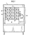
- Figure 1 illustrates a vending machine 1 which contains a variety of products 10 to be dispensed which are stored in an area inaccessible to customers, such as behind a glass panel. Each product 10 is retained by a product delivery apparatus 20 which is selectively actuable to dispense the product into a delivery area 30 that is accessible to the customer.
- Suitable product delivery apparatus 20 includes vend motors and solenoids as well as others well known in the art. Examples of such apparatus include those described in U.S. Patent Nos. 4,458,187 and 4,785,927, which are hereby incorporated by reference.
- Each product may comprise a hot beverage cup containing required powdered drink, and sweetener and/or whitener, as required, to which hot water may be added from an urn (not shown).
- a control panel 40 of the vending machine 1 contains a coin slot 50 which accepts currency to initiate a vend operation.
- a coin return button 75, a coin return recess 80, and an item selector such as a keypad 90 are also provided in the control panel 40.
- the keypad 90 comprises a plurality of buttons 91-99 each corresponding to one of the types of items to be sold.
- a display 70 on the control panel 40 provides instructions and information to the customer. Suitable displays 70 include dot-matrix displays, selectively activatable message lights, an electronic scrolling message, or other displays capable of operating in the environmental conditions to which automatic transaction systems are typically exposed.
- a customer may initiate a transaction by selecting a product 10 to be dispensed using the keypad 90. The customer may then deposit coins of particular denominations in the slots 50. Once sufficient payment has been deposited in the automatic transaction system, the corresponding product delivery apparatus 20 will then dispense the selected product 10 to the product delivery area 30 where it may be retrieved by the customer. Any resulting change from the transaction may be paid out through the coin return recess 80. Before instructing a vend, a customer can press coin return button 75 to obtain a refund of coins in the amount of any coins he has inserted.
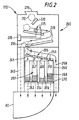
- coin mechanism 110 comprises a coin validator 200, a coin separator 205 and a coin storage region 207.
- the coin validator 200 receives inserted coins 210 through an opening 215 which is connected to the coin inlet 50.
- the coin 210 travels along ramp 220 in the coin validator 200 past sensors such as those shown at 225.
- the sensors 225 generate electrical signals which are provided to a coin mechanism processor 230 such as a microprocessor or microcontroller. Suitable arrangements for sensors 225 include those described in GB 1 397 083, GB 1 443 934, GB 2 254 948 and GB 2 094 008 which are hereby incorporated by reference.
- the processor 230 is connected to the vending machine via communications lines, to be discussed below.
- the electrical signals generated by the sensors 225 contain information corresponding to the measured characteristics of the coin, such as a coin's diameter, thickness, metal content and electromagnetic properties. Based on these electrical signals, the processor 230 is able to discriminate whether the coin is acceptable, and if so, the denomination of the coin 210.
- the processor 230 controls a gate 235 to direct the unacceptable coin 210 to a reject chute 240.
- the reject chute 240 is connected to the coin return recess 80 of Figures 1 and 2.
- acceptable coins 210 are directed to the coin separator 205 by the gate 235.
- the coin separator 205 may have a number of gates 245, 247, 249, 251 arranged along a ramp 253 and also controlled by signals from the processor 230, for diverting the coin 210 from the ramp 253.
- the coin 210 may be diverted into respective containers 262, 264, 266 and 268, or the coin 210 may be allowed to proceed along ramp 253 to a path 258 leading to a cash box (not shown).
- Each of the containers 262, 264, 266 and 268 is in the form of a coin tube arranged to store a vertical stack of coins of a particular denomination. Although only four containers are shown, any number may be provided.
- the coin tubes are arranged within a removable cassette 269; such removable cassettes are well known in the art.
- a removable cassette is described in GB 2246897 A, the contents of which are incorporated herein by reference.
- the coin mechanism 110 may alternatively use passive routing techniques, such as those well known in the vending machine art, instead of the gates 245-251 for diverting the coin 210 from the ramp 253. Examples of suitable alternative configurations for the coin separator 205 are described in U.S. Patent Nos. 3,844,297 and 4,106,610, which are hereby incorporated by reference.
- a dispenser 270 associated with the coin tubes 262-268 is operable to dispense coins from the containers when change is to be given to a customer by the coin mechanism 110.
- the dispensed coins we delivered to the coin return recess 80 for collection.
- Suitable dispensers 270 include those described in U.S. Patent Nos. 3,814,115 and 4,367,760, which are hereby incorporated by reference.
- An alternative configuration may use a coin mechanism 110 that does not payout change. In such a configuration, a separate pre-loaded coin payout device, such as those well known in the gaming machine art, may be used to payout change.
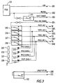
- the lines connecting the vending machine of Figure 1 and the validator of Figure 2 are provided as a multicore cable, carrying a connector which plugs into a socket on the vending machine.
- Each pin on the connector has a specified standardised purpose, to enable different validators to be plugged into a given vending machine.
- Figure 3 illustrates a four price electro-mechanical interface; some pins are omitted for clarity. Figure 3 also shows the components within the validator to which the line from each pin of the connector leads.
- a first pair of pins 301, 302 are for live and neutral voltages respectively, and are connected to a power supply 321 of the validator.
- a pin 303 is connected to a relay 311 controlled by the control unit 230 of the validator.
- the relay is closed on the occurrence of an "exact change" condition (i.e. a condition where the validator can no longer dispense change from the tubes 262-268), connecting the pin 303 to the neutral line from pin 302.
- Pins 305-308 each carry a respective price line from the vending machine. Each is connected to the respective price line relay 315-318 controlled by the processor 230. The relays are wired in series, with the first relay 315 being connected to a common price line appearing at pin 304. Thus, when one of the relays is thrown under control of the processor 230, the corresponding price line is connected to the common terminal 304 and whichever voltage is supplied by the vending machine to the common terminal will appear at that price line terminal. It will be apparent that only one of the price lines can be connected to the common price line terminal, since throwing any one of the relays disconnects all further relays in series with it from the common price line terminal.
- Each of the price lines 305-308 is also connected to the processor 230 via an optical isolator comprising a respective light emitting diode 325-328 in register with a photo-transistor 335-338 connected to the processor 230.
- a credit relay 312 is also provided, under control of the processor 230. When the relay is closed, it interconnects two terminals 309, 310. This may be required by some vending machines to assist in registering the credit. Where the relay itself is not provided, the validator may nonetheless provide an output signal for driving the reed solenoid of the relay.
- Each of the price lines 305-308 is, in the vending machine, connected to at least one respective button 91-94 of the keypad (see Figure 4a).
- Each button comprises a switch, connecting its price line to either live or neutral voltage when pressed by the user.
- a selection button 91-94 a corresponding voltage appears on one of the price line terminals, causing one of the light emitting diodes 325-328 to illuminate, this being detected by the processor 250 via one of the photo-transistors 335-338.
- the vending machine processor 230 determines the corresponding price of the article concerned; accumulates coins until the necessary credit has been received; and then connects the corresponding price line to the common line.
- the vending machine will, typically, have put a voltage on the common line. When this voltage is routed to the price line concerned, it energises the dispense solenoid for the requested item which is then dispensed.
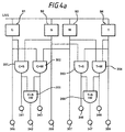
- the vending machine is labelled to indicate to the user that in addition to the items to be selected by depressing the corresponding one of the buttons 91-94, additional items or combinations thereof can be obtained by pressing several of the buttons together.
- the first button 91 may provide black coffee with no sugar if pressed on its own; a second 94 may provide black tea with no sugar if pressed on its own.
- a third button 93 may be labelled for whitener and a fourth 92 for sugar.
- the vending machine is labelled to indicate that pressing buttons 91 and 92 together provides black coffee with sugar; pressing buttons 91 and 93 together provides white coffee without sugar; pressing buttons 91 to 93 altogether provides white coffee with sugar; pressing buttons 94 and 93 provides white tea; pressing buttons 94 and 92 provides tea with sugar, but no whitener; and pressing buttons 92 to 94 together provides white tea with sugar.
- the processor 230 senses, in step 1002, the keys pressed by the user; in step 1004, looks up the record corresponding to the combination of keys; and, in step 1006, reads the stored price of the article concerned.
- step 1008 the processor causes the validator to accept coins in well known fashion until the desired credit level has been reached (step 1010).
- step 1012 one of the relays 315-318 is thrown (for reasons discussed below the identity is not important) and in step 1014, any necessary change is dispensed as disclosed, for instance, in our earlier applications GB 2269258 and GB 2284090.
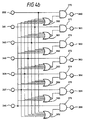
- the solution adopted is to provide a logic circuit (shown in Figures 4a and 4b) to permit the vending machine to directly decode the combination of buttons pressed by the user, so that the vending machine can determine which article or service to dispense.
- Each of the buttons 91-94 comprises a normally open switch connected at one side to the live line, and at the other side to one of the terminals 305-308 as shown in Figure 4a,.
- not all combinations of key presses are meaningful and accordingly, not all are decoded (for example, no article will be dispensed if the buttons for sugar and whitener 92, 93 are pressed together without either tea or coffee).
- the coffee button 91 is connected to a first two-input AND-gate 351, the other side of which is connected to the sugar button 92.
- the output of the AND-gate 351 appears at a node 341, which is therefore high when buttons 91 and 92 are pressed together.
- the coffee button 91 is also connected to a input terminal of a second two input AND-gate 352, the other terminal which is connected to the whitener button 93, and the output of which appears at a port 343.
- the outputs of the gates 351 and 352 are also connected to the inputs of a third two input AND-gate 355, the output of which appears at a node 342 which therefore goes high when all three buttons have been pressed together.
- the tea button 94 is connected to first terminals of a pair of two input AND-gates 353, 354, the second terminals of which are connected respectively to the sugar and whitener buttons 92, 93, the outputs of which appear at nodes 346, 348, and are in turn supplied to a further two input AND-gate 356, the output of which appears at a node 347.
- the nodes 305-308 pass the button presses directly to the coin validator as the user presses the buttons.
- nodes 305-308 and 341-348 are each supplied to one terminal of a respective two input AND-gate 370-376 (nodes 347, 348 and 308, and associated circuits, are omitted from Figure 4b for ease of representation).
- To the other terminal of the AND-gates 370-376 is connected the output of a respective multiple input NOR-gate 380-386.
- the input ports of each NOR-gate are connected to all of the ports 305-308, 341-343, 346-348 other than that which is connected to the associated AND-gate 370-376.
- each of the AND-gates 370-376 is high if, and only if, the port 305-308, 341-343, 346-348 which is connected to it is high and none of the other ports are high (i.e. the output of the NOR-gate is low).
- the states of the AND-gate outputs at nodes 360-366 are used to control respective relays each associated with a desired item (such as a cup of coffee with whitener and sugar). Closure of one of the relays (not shown) interconnects the respective item actuator (energised to cause dispensing of the item) with the price line terminals 305. Thus, when the user has selected an item by the desired combination of buttons, the corresponding item relay is set (and latched). When the validator energises one of its price line relays 315-318 in step 1012, power is supplied through the vending machine relay to the desired item dispense actuator and the vend is performed.
- the validator makes use of one or more relays provided for a different purpose, in addition to the price line relays 315-318, in combination to multiply the number of prices which can be signalled back, and the vending machine includes a logic circuit (shown in Figure 6) to decode such relay combinations.
- the processor 230 consults the item record for the item selected by the user and reads the output relay combination to be used.
- Available relays which could be used in combination with the price line relays include the exact change relay 311 and the credit relay 312; preferably the latter is used in this embodiment.
- eight possible items can be indicated, corresponding to each of four price line relays being set with the credit relay set, and each of the four price line relays being set without the credit relay being set.
- eight such combinations suffice to indicate, as disclosed in the first embodiment, coffee; coffee with sugar; coffee with whitener; coffee with sugar and whitener; tea; tea with sugar; tea with whitener; tea with sugar and whitener.
- each of the terminals 305-308 connected to a respective price line is also connected to one input terminal of each of a pair of AND-gates 401, 421; 402, 422; 403, 423; 404, 424.
- each first AND-gate of the pair, 401-404 is connected, via an invertor 411, to the credit relay terminal 309.
- the other credit relay terminal 310 is connected to the live line.
- the credit relay terminal 309 is connected directly to the second input ports of the second AND-gates 421-424 of each pair, the output of which (appearing at respective nodes 361, 363, 365, 367) are high when the respective price line relay 315-318 is set, and simultaneously, the credit relay 312 is set.
- the signal at each of the nodes 360-367 is used to control a relay connecting power to the selected item actuator to cause a vend.
- the validator is again adapted to operate with a hot beverage vending machine which is operable to dispense tea or coffee, with sugar and/or whitener.
- the operating program of the validator operates as in the first embodiment.
- the vending machine is operable to dispense a predetermined portion of either coffee, tea, sugar, or whitener, into an empty cup in response to activation of a corresponding price line 305-308 by the validator as described in relation to the first embodiment, rather than dispensing a pre-filled cup containing the desired mixture thereof as in the second embodiment.
- the validator is adapted to generate sequential outputs on each of those of lines 305-308 on which button presses were detected in step 1002.
- the validator is operable first to close relay 315 and hold it closed for a period sufficient to perform the dispensing of coffee into a cup; then to open that relay and to close relay 316 and hold it closed for a period sufficient to perform the dispensing of sugar into the cup; then to open that relay and to close relay 317 and hold it closed for a period sufficient to perform the dispensing of whitener into the cup.
- the exact change relay which would only need to be operated for a relatively short period of time, after the user has deposited sufficient coins and before the next vend, so that no confusion to the user should be caused.
- the exact change relay is already closed (i.e. where the validator has no change to dispense) it is temporarily opened before signalling on a price line (or, alternatively, the interface circuit is made to be responsive to a state change on the 'exact change' line rather than to its state).
- Use of both the exact change relay and the credit relay together with the price lines provides a larger number of combinations. Additionally, instead of using these relays in combination they could simply be used as additional price lines.
- signals corresponding to the drive signals for the relay reed solenoids may be used instead (whether the relays themselves are physically present or absent, whether reed relays or other forms of relays are used, or indeed whether circuits other than relays are used).
- buttons should be pressed absolutely simultaneously.
- the processor 230 it would be possible simply to program the processor 230 to monitor occurrence of several buttons within a defined period of time (perhaps on the order of a second or so).
- modification would need to be made to the vending machine hardware of Figure 4, to permit button presses to be latched and held for a period of, for example, a second or so, using a trigger or monostable circuit.
- the interface circuits described above may be implemented as a look-up table PROM, or as a low-cost microprocessor, or other integrated circuit.
- the validator may look up a price for each line (tea, sugar, whitener) and then calculate a combined price by adding the individual prices, thus allowing for differential pricing for additives.
Landscapes
- Physics & Mathematics (AREA)
- General Physics & Mathematics (AREA)
- Control Of Vending Devices And Auxiliary Devices For Vending Devices (AREA)
- Financial Or Insurance-Related Operations Such As Payment And Settlement (AREA)
Applications Claiming Priority (2)
| Application Number | Priority Date | Filing Date | Title |
|---|---|---|---|
| GB9911674A GB2350223B (en) | 1999-05-19 | 1999-05-19 | Money handling interface and method |
| GB9911674 | 1999-05-19 |
Publications (2)
| Publication Number | Publication Date |
|---|---|
| EP1054367A2 true EP1054367A2 (fr) | 2000-11-22 |
| EP1054367A3 EP1054367A3 (fr) | 2003-07-09 |
Family
ID=10853769
Family Applications (1)
| Application Number | Title | Priority Date | Filing Date |
|---|---|---|---|
| EP00302914A Withdrawn EP1054367A3 (fr) | 1999-05-19 | 2000-04-06 | Interface pour le traitement de la monnaie et méthode |
Country Status (3)
| Country | Link |
|---|---|
| US (1) | US6422373B1 (fr) |
| EP (1) | EP1054367A3 (fr) |
| GB (1) | GB2350223B (fr) |
Families Citing this family (5)
| Publication number | Priority date | Publication date | Assignee | Title |
|---|---|---|---|---|
| US8041453B2 (en) * | 2004-09-27 | 2011-10-18 | Walker Digital, Llc | Method and apparatus for defining and utilizing product location in a vending machine |
| US8827777B2 (en) * | 2007-05-24 | 2014-09-09 | National Rejectors, Inc. Gmbh | Method for operating a coin dispensing device and a coin dispensing device |
| AU2024218399A1 (en) * | 2023-02-10 | 2025-01-30 | 1Inch Limited | Dynamic multi-path transfers |
| US12608709B2 (en) | 2024-03-15 | 2026-04-21 | Degensoft Ltd. | Decentralized systems and methods for response generation to API calls |
| US12574234B2 (en) | 2024-04-18 | 2026-03-10 | Degensoft Ltd | Secure cross-chain atomic swaps |
Family Cites Families (11)
| Publication number | Priority date | Publication date | Assignee | Title |
|---|---|---|---|---|
| US3645441A (en) * | 1968-10-28 | 1972-02-29 | Olivetti & Co Spa | Keyboard for a desk computer |
| US3963035A (en) * | 1973-07-23 | 1976-06-15 | H. R. Electronics Company | Coin controlled circuits for vending and other coin controlled devices |
| JPS5269399A (en) * | 1975-12-05 | 1977-06-09 | Nippon Koinko Kk | Controlling method for automatic vending machine |
| JPS5657191A (en) * | 1979-10-16 | 1981-05-19 | Nippon Coinco Co Ltd | Controller for vendor |
| US4495485A (en) | 1980-12-12 | 1985-01-22 | General Electric Company | Touch control arrangement for data entry |
| US4429301A (en) | 1981-10-26 | 1984-01-31 | Amp Incorporated | Means for decoding a switch array |
| US4498570A (en) | 1982-01-29 | 1985-02-12 | The Coca-Cola Company | Multiple purchase discount module for a single price vending machine |
| JPS59184998A (ja) * | 1983-04-05 | 1984-10-20 | サンデン株式会社 | 複数品種のコ−ヒ−をブレンドして販売可能とした自動販売機 |
| JPH0644212B2 (ja) * | 1987-06-16 | 1994-06-08 | 日本電気株式会社 | キ−入力装置 |
| US5561604A (en) * | 1988-12-08 | 1996-10-01 | Hallmark Cards, Incorporated | Computer controlled system for vending personalized products |
| JP3441548B2 (ja) | 1995-02-06 | 2003-09-02 | 株式会社トミー | 自動販売機における硬貨選別装置 |
-
1999
- 1999-05-19 GB GB9911674A patent/GB2350223B/en not_active Expired - Fee Related
-
2000
- 2000-04-06 EP EP00302914A patent/EP1054367A3/fr not_active Withdrawn
- 2000-05-16 US US09/571,546 patent/US6422373B1/en not_active Expired - Lifetime
Also Published As
| Publication number | Publication date |
|---|---|
| GB9911674D0 (en) | 1999-07-21 |
| EP1054367A3 (fr) | 2003-07-09 |
| GB2350223B (en) | 2003-08-06 |
| US6422373B1 (en) | 2002-07-23 |
| GB2350223A (en) | 2000-11-22 |
Similar Documents
| Publication | Publication Date | Title |
|---|---|---|
| EP1045351B2 (fr) | Machine pour traiter de la monnaie avec accès périphérique | |
| US5831862A (en) | Automatic transaction system with a dynamic display and methods of its operation | |
| US5450938A (en) | Card or cash actuated vending machine assembly | |
| USRE35649E (en) | Method and apparatus for the control of a multiple of door accessible newspaper vending cabinets with a single vend control mechanism operating remote door latches | |
| US20040249501A1 (en) | Enhanced bill acceptor/dispenser for vending machines | |
| US5566807A (en) | Coin acceptance method and apparatus | |
| EP1050854A2 (fr) | Dispositif de traitement d'argent et méthode | |
| EP1071047B1 (fr) | Système et procédé de transaction automatique pour des monnaies multiples | |
| US6994202B1 (en) | Money acceptance method and apparatus | |
| US6796415B2 (en) | Loose coin and rolled coin dispenser | |
| EP1065632A2 (fr) | Détecteur de monnaies dans des machines automatiques | |
| US6422373B1 (en) | Money handling interface and method | |
| MXPA97001975A (es) | Sistema y metodo de transaccion automatica de multiples divisas | |
| EP0993661B1 (fr) | Procede de fonctionnement d'un mecanisme de pieces de monnaie | |
| US3250363A (en) | Dispensing control apparatus | |
| JP4428015B2 (ja) | 自動販売機 | |
| JP3436282B2 (ja) | 紙幣・硬貨等取忘れ防止機能付き両替機 | |
| JPS6225232B2 (fr) | ||
| HK1013715A (en) | Coin acceptance method and apparatus | |
| JPH08287300A (ja) | 自動販売機 | |
| JPS6252356B2 (fr) | ||
| JPH0521760B2 (fr) | ||
| JPH11296723A (ja) | コイン処理装置 | |
| JPH02267690A (ja) | 自動販売機の価格設定装置 | |
| JPS63296193A (ja) | 自動販売機 |
Legal Events
| Date | Code | Title | Description |
|---|---|---|---|
| PUAI | Public reference made under article 153(3) epc to a published international application that has entered the european phase |
Free format text: ORIGINAL CODE: 0009012 |
|
| AK | Designated contracting states |
Kind code of ref document: A2 Designated state(s): AT BE CH CY DE DK ES FI FR GB GR IE IT LI LU MC NL PT SE |
|
| AX | Request for extension of the european patent |
Free format text: AL;LT;LV;MK;RO;SI |
|
| PUAL | Search report despatched |
Free format text: ORIGINAL CODE: 0009013 |
|
| RIC1 | Information provided on ipc code assigned before grant |
Ipc: 7H 03M 11/20 A |
|
| AK | Designated contracting states |
Designated state(s): AT BE CH CY DE DK ES FI FR GB GR IE IT LI LU MC NL PT SE |
|
| AX | Request for extension of the european patent |
Extension state: AL LT LV MK RO SI |
|
| 17P | Request for examination filed |
Effective date: 20040106 |
|
| AKX | Designation fees paid |
Designated state(s): DE ES FR GB |
|
| 17Q | First examination report despatched |
Effective date: 20041008 |
|
| STAA | Information on the status of an ep patent application or granted ep patent |
Free format text: STATUS: THE APPLICATION IS DEEMED TO BE WITHDRAWN |
|
| 18D | Application deemed to be withdrawn |
Effective date: 20050219 |