EP1054466A2 - Dispositif de traitement de signal pour décaler la phase d' un signal d' entrée et pour atténuer le signal - Google Patents
Dispositif de traitement de signal pour décaler la phase d' un signal d' entrée et pour atténuer le signal Download PDFInfo
- Publication number
- EP1054466A2 EP1054466A2 EP00401389A EP00401389A EP1054466A2 EP 1054466 A2 EP1054466 A2 EP 1054466A2 EP 00401389 A EP00401389 A EP 00401389A EP 00401389 A EP00401389 A EP 00401389A EP 1054466 A2 EP1054466 A2 EP 1054466A2
- Authority
- EP
- European Patent Office
- Prior art keywords
- signal
- processing apparatus
- shaft
- recited
- members
- Prior art date
- Legal status (The legal status is an assumption and is not a legal conclusion. Google has not performed a legal analysis and makes no representation as to the accuracy of the status listed.)
- Withdrawn
Links
Images







Classifications
-
- H—ELECTRICITY
- H01—ELECTRIC ELEMENTS
- H01P—WAVEGUIDES; RESONATORS, LINES, OR OTHER DEVICES OF THE WAVEGUIDE TYPE
- H01P1/00—Auxiliary devices
- H01P1/18—Phase-shifters
-
- H—ELECTRICITY
- H01—ELECTRIC ELEMENTS
- H01P—WAVEGUIDES; RESONATORS, LINES, OR OTHER DEVICES OF THE WAVEGUIDE TYPE
- H01P1/00—Auxiliary devices
- H01P1/18—Phase-shifters
- H01P1/184—Strip line phase-shifters
-
- H—ELECTRICITY
- H01—ELECTRIC ELEMENTS
- H01P—WAVEGUIDES; RESONATORS, LINES, OR OTHER DEVICES OF THE WAVEGUIDE TYPE
- H01P1/00—Auxiliary devices
- H01P1/22—Attenuating devices
-
- H—ELECTRICITY
- H01—ELECTRIC ELEMENTS
- H01P—WAVEGUIDES; RESONATORS, LINES, OR OTHER DEVICES OF THE WAVEGUIDE TYPE
- H01P1/00—Auxiliary devices
- H01P1/22—Attenuating devices
- H01P1/227—Strip line attenuators
-
- H—ELECTRICITY
- H01—ELECTRIC ELEMENTS
- H01P—WAVEGUIDES; RESONATORS, LINES, OR OTHER DEVICES OF THE WAVEGUIDE TYPE
- H01P3/00—Waveguides; Transmission lines of the waveguide type
- H01P3/12—Hollow waveguides
Definitions
- the present invention relates to a signal-processing apparatus for shifting phase of a signal inputted thereto and attenuating the signal and, more particularly, to a signal-processing apparatus capable of stably operating without regard to outside circumstances such as a temperature etc. and miniaturizing.
- a communication system needs a signal-processing apparatus such as a phase shifter for shifting phase of a signal inputted thereto and an attenuator for attenuating the signal and so on.
- a signal-processing apparatus such as a phase shifter for shifting phase of a signal inputted thereto and an attenuator for attenuating the signal and so on.
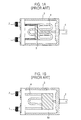
- FIGs. 1A and 1B there are shown a conventional signal-processing apparatus for shifting phase of a signal inputted thereto and attenuating the signal.
- the conventional signal-processing apparatus includes a hollow housing 3, input and output connectors 1 and 2 coupled to a side of the housing 3, a W-shaped conductor 4 having both ends respectively connected to the input and output connectors 1 and 2, a dielectric material 5 movably connected to the conductor 4 and a handle 6 rotatably coupled to the other side of the housing 3.
- the handle 6 is used for providing a moving force to the dielectric material 5.
- total length of the arrow represents that of a transmission line for passing the inputted signal.
- the conventional signal-processing apparatus functions as a phase shifter. That is, when the handle 6 is rotated and the conductor 4 is moved left or right, total length of the transmission line is changed and, therefore, phase of the inputted signal is shifted and the transmission time of the signal is delayed.
- the conventional apparatus when the dielectric material is replaced with an absorber 50 as shown in Fig. 1B, the conventional apparatus functions as an attenuator. That is, the absorber 50 attenuates a radio wave passing the conductor 4.
- another conventional signal-processing apparatus has an electric device, such as a diode, functioning as a transmission line of a signal inputted to an input connector.
- a signal-processing apparatus for shifting phase of a signal inputted thereto and attenuating the signal, comprising: an input connector for inputting a signal; an output connector for outputting the signal; a rotational force supplying means for generating a rotational force; a rotation body to be rotated by the rotational force provided from the rotational force supplying means; a plurality of rotatable members respectively having a groove in peripheral portion, the rotatable members being coupled to peripheral portion of the rotation body so that the grooves communicate with each other; and a signal transmitting member for transmitting the inputted signal to the output connector, the signal transmitting member being located in the grooves and its both ends being respectively connected to the input and output connectors.
- a signal-processing apparatus for shifting phase of a signal inputted thereto and attenuating the signal, comprising; an input connector for inputting a signal; an output connector for outputting the signal; a rotation body to be rotated by the rotational force provided from the rotational force supplying means, the rotation body having an annular opening at lower portion thereof and being made of conductor; a plurality of rotatable members respectively having a groove in lower portion, the rotatable members being coupled to peripheral portion of the rotation body so that the grooves communicate with each other; and a signal transmitting member having terminals respectively connected to the input and output connectors so that the signal inputted to the input connector is transmitted to the output connector, the signal transmitting member being located in the groove.
- a signal-processing apparatus for shifting phase of a signal inputted thereto and attenuating the signal, comprising; an input connector for inputting a signal; an output connector for outputting the signal; a first rotation body to be rotated by a rotational force, the first rotation body having a first shaft connected to the rotational force supplying means and a first disk coupled to peripheral portion of the first shaft to be moved together with the first shaft; a first member coupled to peripheral portion of the first shaft to be moved together with the first shaft; a second member coupled to peripheral portion of the first shaft, against to the first member, to be moved together with the first shaft; and a signal transmitting member for transmitting the signal inputted through the input connector to the output connector, the signal transmitting member being located under the first and second members and its both ends being respectively connected to the input and output connectors.
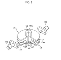
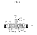
- FIG. 2 to 4 there is shown a signal-processing apparatus of a first embodiment in accordance with a present invention.
- the signal-processing apparatus in accordance with first embodiment of the present invention comprises a housing 110(see Fig. 4), an outer conductor 120 rotatably coupled within the housing 110, a first and second members 132 and 134 coupled within the outer conductor 120 to rotate together with the outer conductor 120, an input connector 140 coupled to a side of the housing 110, an output connector 150 coupled to a side of the housing 110 opposite to the input connector 140 and an inner conductor 160 located within the first and second members 132 and 134. Both ends of the inner conductor 160 are respectively connected to the input and output conductors 140 and 150 to retain its place.
- the first and second members 132 and 134 respectively take the shape of semicircle and the inner conductor 160 takes the shape of substantial semicircular arch.
- the outer conductor 120 includes a shaft 122 passing the upper portion of the housing 110 and first and second disks 124 and 126 positioned at peripheral portion of the shaft 122.
- the first and second disks 124 and 126 are spaced out a predetermined distance on upper and lower portions of the shaft 122 so that the first and second members 132 and 134 are fitted therebetween.
- upper portion of the shaft 122 has a recess 122a to connect a motor (not shown) for providing a rotational force.
- the shaft 122 is perpendicular to the first and second disks 124 and 126.
- the shaft 122, first and second disks 124 and 126 are integrally formed.
- first and second members 132 and 134 respectively have first and second grooves 132a and 134a in which the inner conductor 160 is coupled. Height of the second groove 134a is higher than that of the first groove 132a.
- the signal-processing apparatus functions as a phase shifter. That is, when the shaft 122 is rotated, the first and second dielectric materials 132 and 134 are rotated together with the first and second disks 124 and 126 and the inner conductor 160 retains its original position. In this case, dielectric constant around the inner conductor 160 is continuously changed as the rotation of the shaft 122. Therefore, while a signal inputted to the input connector 140 is transmitted to the output connector 150 through the inner conductor 160, phase of the signal is shifted so that a transmission time of the signal is delayed.
- each of the phase shift and delay time has maximum value.
- each of the phase shift and delay time has minimum value.
- each of the phase shift and delay time has value between the maximum value and the minimum value.
- the signal-processing apparatus of the first embodiment functions as an attenuator. That is, when a signal inputted to the input connector 140 is passed through the inner conductor 160, the signal is attenuated by the absorber and, then, be outputted from the output connector 150.
- FIGs. 5A to 5C there are perspective views illustrating various modifications of the first embodiment adapted to a printed circuit board.
- PCB printed circuit board
- Fig. SC the both ends of the inner conductor 160 are folded several times to be directly fixed to a mounter of the PCB.
- FIG. 6 there is shown a plan view showing another application of the first embodiment in accordance with the present invention.
- the signal-processing apparatus consists of a phase shifter "A" which the first and second members are made of dielectric material respectively having dielectric constants different from each other and an attenuator "B" which the first and second members are made of absorbers.
- an end of inner conductor 160 of the phase shifter "A” is connected to an end of inner conductor 160 of the attenuator "B".
- the other end of inner conductor 160 of the phase shifter "A” is connected to the input connector 140 and the other end of inner conductor 160 of the attenuator "B” is connected to the out connector 150. Then, the signal-processing apparatus can simultaneously perform functions as the phase shifter and attenuator.
- the driving shaft of a motor 170 is fitted to the recess 122a of the shaft 122.
- rotation of the shaft 122 is controlled by controlling the operation of the motor 170.
- the motor 170 can be remote-controlled.
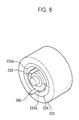
- FIGs. 8 and 9 there is shown a second embodiment of the signal-processing apparatus in accordance with the present invention.
- the signal-processing apparatus of the second embodiment comprises an outer conductor 220 coupled in a housing 210.
- the conductor 220 includes a protrusion 222 having a recess 222a for fitting a driving shaft of motor on upper portion thereof and an annular opening for fixing first and second members 232 and 234 in lower portion thereof.
- the first and second members 232 and 234 respectively have a first and second grooves 232a and 234a in which an inner conductor 260 is positioned.
- the first groove 232a is communicated with the second groove 234a. Size of the first groove 232a is larger than that of the second groove 234a.
- Transversal cross-section of the inner conductor 260 substantially has a semicircular arch-shape.
- the inner conductor 260 has a pair of terminals formed in lower ends thereof and passing the housing 210.
- the terminals are respectively connected to an input and output connectors 240 and 250 coupled to lower portion of the housing 210. Therefore, the inner conductor 260 always retains its origin position.
- the input and output connectors 240 and 250 are parallel with the protrusion 222.
- the signal-processing apparatus functions as a phase shifter. Further, if the first and second members 232 and 234 are respectively made of a first and second absorbers capable of absorbing a radio wave, i.e., ferrite, the signal-processing apparatus of the first embodiment functions as an attenuator. Since operation of the signal-processing apparatus in the second embodiment is similar to that of the first embodiment, the operation description of the second embodiment will be omitted.
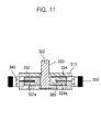
- FIGs. 10 and 11 there is shown a third embodiment of the signal-processing apparatus in accordance with the present invention.
- the signal-processing apparatus of the third embodiment comprises a housing 310, a shaft 320 having upper portion protruded from the housing 310, first and second members 332 and 334 fixed to peripheral portion of the shaft 320, an input and output connectors 340 and 350 respectively coupled to both sides of the housing 310, and an inner conductor 360 located within the first and second members 332 and 334.
- the shaft 320 has a recess 322 formed on the upper portion to fit a driving shaft of motor.
- Each of the first and second members 332 and 334 takes the shape of semicircle and has first and second grooves 332a and 334a respectively formed on the peripheral portion thereof.
- the inner conductor 360 takes the shape of semicircular arch substantially.
- first and second members 332 and 334 are fixed to the shaft 322 so that the first groove 332a is communicated with the second groove 334a.
- the signal-processing apparatus functions as a phase shifter. Further, if the first and second members 332 and 334 are respectively made of a first and second absorbers capable of absorbing a radio wave, i.e., ferrite, the signal-processing apparatus of the third embodiment functions as an attenuator. Since operation of the signal-processing apparatus in the third embodiment is similar to that of the first embodiment, the operation description of the third embodiment will be omitted.
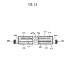
- FIGs. 12 and 13 there is shown a fourth embodiment of the signal-processing apparatus in accordance with the present invention.
- the signal-processing apparatus of the fourth embodiment comprises a housing 410 and an outer conductor 420 coupled in the housing 410.
- the housing 410 includes a box 412 having an opening at its upper portion and a cover 414 for closing the opening of the box 412.
- the box 412 has a pair of cut portions formed on both upper portions thereof and a concave portion 413 formed on bottom surface thereof.
- the cover 414 has a pair of protrusions respectively inserted into the cut portions and a through hole 415 formed on a portion opposite to the concave portion 413. When the cover 414 closes the opening of the box 412, predetermined spaces are respectively formed between each of the cut portions of the box 412 and each of the protrusions of the cover 414.
- the outer conductor 420 includes a shaft 422 to be connected to a motor(not shown) and a disk 424 coupled to peripheral portion of the shaft 422. Further, the shaft 422 has a recess 422a for fitting a driving shaft of the motor on top surface thereof. In this case, upper and lower portions of the shaft 422 are respectively supported at the concave portion 413 of the box 412 and the through hole 415 of the cover 414.
- the disk 424 is integrally formed with the shaft 422 or has a through hole at center portion thereof to fix the shaft 422.
- the signal-processing apparatus of this embodiment also has first and second members 432 and 434 respectively coupled to peripheral portion of the shaft 422 and a printed circuit board (hereinafter, referred to PCB) 440 having a through hole 442 for passing the shaft 422 at center portion thereof.
- the first and second members 432 and 434 take the shape of substantial semicircle and respectively have thickness different from each other.
- the PCB 440 has a substantial semicircular arch-shaped transmission line 444 coated with a conductive materials.
- the rest portion of the PCB 440 except the transmission line 444 is preferably made of non-conductive materials.
- Both ends of the transmission line 444 are respectively protruded from spaces formed between each of the cut portions of the box 412 and each of the protrusions of the cover 414. In this case, the both ends of the transmission line 444 are respectively connected to input and output connectors 450 and 460 coupled to both sides of the housing 410.
- the signal-processing apparatus of the fourth embodiment functions as a phase shifter. Further, if the first and second members 432 and 434 are respectively made of a first and second absorbers capable of absorbing a radio wave, i.e., ferrite, the signal-processing apparatus of the fourth embodiment functions as an attenuator. Since operation of the signal-processing apparatus in the fourth embodiment is similar to that of the first embodiment, the operation description of the fourth embodiment will be omitted.
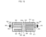
- FIGs. 14 and 15 there is shown a fifth embodiment of the signal-processing apparatus in accordance with the present invention.
- the signal-processing apparatus of the fifth embodiment comprises a housing 510 including a box 512 and cover 514 respectively similar to box and cover in the fourth embodiment and first and second outer conductors 520 and 530 coupled in the housing 510.
- the first outer conductor 520 has a first shaft 522 connected to a motor (not shown) and a first disk 524 coupled to peripheral portion of the first shaft 522.
- the second conductor 530 has a second shaft 532 to be joined to the first shaft 522 and a second disk 534 coupled to peripheral portion of the second shaft 532.
- each of the first and second conductors 520 and 530 is integrally formed.
- the first shaft 522 includes a recess 522a for fitting a driving shaft of the motor on upper portion thereof and a first longitudinal hole for joining a screw 536 on lower portion thereof.
- Lower portion of the second shaft 532 is rotatably coupled to a concave portion 513 of the box 512 and has a second longitudinal hole 532a for joining the screw 536.
- the first and second shafts 522 and 532 are coupled by the screw 536 joined to the first longitudinal hole through the second longitudinal hole 532a.
- the lower portion of the second longitudinal hole 532a is preferably formed to accommodate the head of the screw 536.
- the signal-processing apparatus of the fifth embodiment has first and second members 542 and 544 coupled to peripheral portion of the first shaft 522 and a third and fourth members 546 and 548 coupled to peripheral portion of the second shaft 532.
- the first to fourth members 542 to 548 have a semicircle-shaped section.
- the first and second members 542 and 544 are spaced out a predetermined distance from the third and fourth members 546 and 548.
- the signal-processing apparatus of the fifth embodiment also has a printed circuit board (hereinafter, referred to PCB) 550 coupled in space between the members coupled to the first shaft 522 and the members coupled to the second shaft 532.
- the PCB 550 has a through hole 552 for passing the shaft.
- the first and third members 542 and 546 respectively have thickness different from the second and fourth members 544 and 548. Therefore, the space between the firth and third members 542 and 546 is larger than that between the second and fourth members 544 and 548.
- the PCB 550 has a transmission line 554 coated with conductive materials thereon and the rest of the PCB 550 except the transmission line 554 is coated with non-conductive materials.
- the transmission line 554 is formed in substantial semicircular arch-shape and its both ends are respectively protruded from both sides of the housing 510. The both ends of the transmission line 554 are respectively connected to input and output connectors 560 and 570.
- the signal-processing apparatus functions as a phase shifter. Further, if the first to fourth members 542 to 548 are respectively made of absorbers capable of absorbing a radio wave, i.e., ferrite, the signal-processing apparatus of the fifth embodiment functions as an attenuator. Since operation of the signal-processing apparatus in the fifth embodiment is similar to that of the first embodiment, the operation description of the fifth embodiment will be omitted.
- the signal-processing apparatus can miniaturize and be stably operated without regard to outside circumstance because an electric device is not installed.
- signal-processing apparatus of the present invention uses a printed circuit board as a transmission line for an inputted signal, the manufacturing process is simple and, therefore, production efficiency of the signal-processing apparatus is improved and cost is reduced.
Landscapes
- Waveguide Switches, Polarizers, And Phase Shifters (AREA)
- Arrangements For Transmission Of Measured Signals (AREA)
- Non-Reversible Transmitting Devices (AREA)
Applications Claiming Priority (4)
| Application Number | Priority Date | Filing Date | Title |
|---|---|---|---|
| KR9917968 | 1999-05-19 | ||
| KR19990017968 | 1999-05-19 | ||
| KR1019990033577A KR20000075389A (ko) | 1999-05-19 | 1999-08-16 | 입력된 신호의 위상천이 및 감쇄를 위한 신호 처리장치 |
| KR9933577 | 1999-08-16 |
Publications (2)
| Publication Number | Publication Date |
|---|---|
| EP1054466A2 true EP1054466A2 (fr) | 2000-11-22 |
| EP1054466A3 EP1054466A3 (fr) | 2002-03-06 |
Family
ID=26635174
Family Applications (1)
| Application Number | Title | Priority Date | Filing Date |
|---|---|---|---|
| EP00401389A Withdrawn EP1054466A3 (fr) | 1999-05-19 | 2000-05-19 | Dispositif de traitement de signal pour décaler la phase d' un signal d' entrée et pour atténuer le signal |
Country Status (4)
| Country | Link |
|---|---|
| US (1) | US6392507B1 (fr) |
| EP (1) | EP1054466A3 (fr) |
| JP (1) | JP2000353902A (fr) |
| KR (1) | KR20000075389A (fr) |
Cited By (6)
| Publication number | Priority date | Publication date | Assignee | Title |
|---|---|---|---|---|
| EP1251586A3 (fr) * | 2001-04-16 | 2004-01-21 | Murata Manufacturing Co., Ltd. | Déphaseur, antenne réseau à commande de phase et appareil radar |
| EP1568097A4 (fr) * | 2002-11-08 | 2006-08-23 | Ems Technologies Inc | Repartiteur de puissance variable |
| US7221239B2 (en) | 2002-11-08 | 2007-05-22 | Andrew Corporation | Variable power divider |
| EP1804329A4 (fr) * | 2004-10-13 | 2007-10-10 | Yuejun Yan | Attenuateur variable |
| US7557675B2 (en) | 2005-03-22 | 2009-07-07 | Radiacion Y Microondas, S.A. | Broad band mechanical phase shifter |
| WO2015150168A1 (fr) * | 2014-04-04 | 2015-10-08 | Filtronic Wireless Ab | Déphaseur à impédance constante réglable |
Families Citing this family (9)
| Publication number | Priority date | Publication date | Assignee | Title |
|---|---|---|---|---|
| KR100552122B1 (ko) * | 2001-03-02 | 2006-02-13 | 주식회사 케이엠더블유 | 비접점 다중 전송선로용 위상천이 및 감쇄를 위한신호처리장치 |
| GB0125349D0 (en) * | 2001-10-22 | 2001-12-12 | Qinetiq Ltd | Antenna system |
| KR100817159B1 (ko) * | 2004-08-20 | 2008-03-27 | 주식회사 케이엠더블유 | 가변 이상기 |
| KR101027920B1 (ko) * | 2008-08-11 | 2011-04-12 | 주식회사 에이스테크놀로지 | 프린징 필드를 차단하는 페이즈 쉬프터 및 이를 포함하는 안테나 |
| JP4650561B2 (ja) * | 2008-12-02 | 2011-03-16 | 住友電気工業株式会社 | 移相器 |
| JP5773677B2 (ja) | 2011-02-10 | 2015-09-02 | キヤノン株式会社 | プリント回路板 |
| KR102076525B1 (ko) * | 2013-07-16 | 2020-02-12 | 엘지이노텍 주식회사 | 위상변환기 및 이를 구비하는 송신 시스템 |
| CN103715488B (zh) * | 2013-12-05 | 2016-05-11 | 成都九洲迪飞科技有限责任公司 | L波段和差器 |
| CN111342175B (zh) * | 2020-03-13 | 2022-02-25 | 佛山市粤海信通讯有限公司 | 一种带状线移相器和天线 |
Family Cites Families (7)
| Publication number | Priority date | Publication date | Assignee | Title |
|---|---|---|---|---|
| US3119081A (en) * | 1961-09-25 | 1964-01-21 | Lab For Electronics Inc | Microwave attenuator |
| WO1984001473A1 (fr) * | 1982-09-29 | 1984-04-12 | Hughes Aircraft Co | Attenuateur variable de micro-ondes |
| US4721959A (en) * | 1984-12-07 | 1988-01-26 | Alpha Industries, Inc. | Monopulse comparator formed in a milled channel plate structure |
| US4824399A (en) * | 1987-06-19 | 1989-04-25 | Amp Incorporated | Phase shifter |
| US4788515A (en) * | 1988-02-19 | 1988-11-29 | Hughes Aircraft Company | Dielectric loaded adjustable phase shifting apparatus |
| US5376905A (en) * | 1993-08-23 | 1994-12-27 | Hughes Aircraft Company | Rotary vane variable power divider |
| US5877660A (en) * | 1994-06-02 | 1999-03-02 | Nihon Dengyo Kosaku Co., Ltd. | Phase shifting device with rotatable cylindrical case having driver means on the end walls |
-
1999
- 1999-08-16 KR KR1019990033577A patent/KR20000075389A/ko not_active Ceased
-
2000
- 2000-05-18 US US09/572,972 patent/US6392507B1/en not_active Expired - Fee Related
- 2000-05-19 JP JP2000148666A patent/JP2000353902A/ja active Pending
- 2000-05-19 EP EP00401389A patent/EP1054466A3/fr not_active Withdrawn
Cited By (8)
| Publication number | Priority date | Publication date | Assignee | Title |
|---|---|---|---|---|
| EP1251586A3 (fr) * | 2001-04-16 | 2004-01-21 | Murata Manufacturing Co., Ltd. | Déphaseur, antenne réseau à commande de phase et appareil radar |
| US6737938B2 (en) | 2001-04-16 | 2004-05-18 | Murata Manufacturing Co., Ltd. | Phase shifter, phased-array antenna, and radar |
| EP1568097A4 (fr) * | 2002-11-08 | 2006-08-23 | Ems Technologies Inc | Repartiteur de puissance variable |
| US7221239B2 (en) | 2002-11-08 | 2007-05-22 | Andrew Corporation | Variable power divider |
| EP1804329A4 (fr) * | 2004-10-13 | 2007-10-10 | Yuejun Yan | Attenuateur variable |
| US7557675B2 (en) | 2005-03-22 | 2009-07-07 | Radiacion Y Microondas, S.A. | Broad band mechanical phase shifter |
| WO2015150168A1 (fr) * | 2014-04-04 | 2015-10-08 | Filtronic Wireless Ab | Déphaseur à impédance constante réglable |
| US9972878B2 (en) | 2014-04-04 | 2018-05-15 | Filtronic Wireless Ab | Adjustable constant impedance phase shifter |
Also Published As
| Publication number | Publication date |
|---|---|
| KR20000075389A (ko) | 2000-12-15 |
| EP1054466A3 (fr) | 2002-03-06 |
| JP2000353902A (ja) | 2000-12-19 |
| US6392507B1 (en) | 2002-05-21 |
Similar Documents
| Publication | Publication Date | Title |
|---|---|---|
| EP1054466A2 (fr) | Dispositif de traitement de signal pour décaler la phase d' un signal d' entrée et pour atténuer le signal | |
| AU2002356968B2 (en) | Electromagnetic coupling | |
| KR20200087728A (ko) | 전기 단자들의 플러그-인 접속을 위한 장치 및 상기 장치를 구비한 압축기 구동 장치 | |
| EP0214238B1 (fr) | Dephaseur coaxial pour ligne electromagnetique transversale de transmission | |
| US6504450B2 (en) | Signal process apparatus for phase-shifting N number of signals inputted thereto | |
| WO2003107491A1 (fr) | Cable coaxial avec prise | |
| US5382932A (en) | Electronic components and systems using coaxial cable | |
| EP1677381A1 (fr) | Dispositif de conversion de guide d'ondes, joint tournant de guide d'ondes et dispositif d'antenne | |
| CA2256283C (fr) | Guide d'ondes dielectrique non radiatif comprenant une partie pour la conversion de ligne entre differents types de guides d'ondes dielectriques non radiatifs | |
| AU4086000A (en) | Waveguide twist | |
| CN1781211B (zh) | 小型非辐射介质波导线路导波模式抑制器 | |
| US5890923A (en) | Connector alignment guide | |
| KR100468985B1 (ko) | 커넥터및커넥터키트 | |
| KR100997222B1 (ko) | 사전설정된 거리만큼 이격하여 적층된 복수의 회로보드를 구비한 모듈 및 상기 모듈용 광커넥터 | |
| CA1233892A (fr) | Interrupteur pour reseau de cable coaxial a conducteur central de section carree | |
| KR100474878B1 (ko) | 커넥터조립체 | |
| JP4212712B2 (ja) | 導線接続用端子部材 | |
| JP3520472B2 (ja) | 結合度調整機能付き方向性結合器 | |
| EP1388189B1 (fr) | Appareil permettant de connecter des lignes de transmission | |
| KR100441309B1 (ko) | 콘넥터형 위상기 | |
| EP0809318B1 (fr) | Circulateur | |
| JP7792454B2 (ja) | 改良されたシールドと一体に折り曲げられたハウジングとを備えるコンタクトモジュール | |
| CN114447564A (zh) | 一种天线装置及遥控器 | |
| JP2024098357A (ja) | 導波管接続構造 | |
| CN118659152A (zh) | 连接器、天线系统及插头系统 |
Legal Events
| Date | Code | Title | Description |
|---|---|---|---|
| PUAI | Public reference made under article 153(3) epc to a published international application that has entered the european phase |
Free format text: ORIGINAL CODE: 0009012 |
|
| AK | Designated contracting states |
Kind code of ref document: A2 Designated state(s): DE FI FR SE Kind code of ref document: A2 Designated state(s): AT BE CH CY DE DK ES FI FR GB GR IE IT LI LU MC NL PT SE |
|
| AX | Request for extension of the european patent |
Free format text: AL;LT;LV;MK;RO;SI |
|
| PUAL | Search report despatched |
Free format text: ORIGINAL CODE: 0009013 |
|
| AK | Designated contracting states |
Kind code of ref document: A3 Designated state(s): AT BE CH CY DE DK ES FI FR GB GR IE IT LI LU MC NL PT SE |
|
| AX | Request for extension of the european patent |
Free format text: AL;LT;LV;MK;RO;SI |
|
| 17P | Request for examination filed |
Effective date: 20020430 |
|
| AKX | Designation fees paid |
Free format text: DE FI FR SE |
|
| STAA | Information on the status of an ep patent application or granted ep patent |
Free format text: STATUS: THE APPLICATION IS DEEMED TO BE WITHDRAWN |
|
| 18D | Application deemed to be withdrawn |
Effective date: 20051201 |