EP1054470A2 - Antenne mit geringem visuellen Eindruck - Google Patents
Antenne mit geringem visuellen Eindruck Download PDFInfo
- Publication number
- EP1054470A2 EP1054470A2 EP99113907A EP99113907A EP1054470A2 EP 1054470 A2 EP1054470 A2 EP 1054470A2 EP 99113907 A EP99113907 A EP 99113907A EP 99113907 A EP99113907 A EP 99113907A EP 1054470 A2 EP1054470 A2 EP 1054470A2
- Authority
- EP
- European Patent Office
- Prior art keywords
- screen
- antenna
- antenna according
- reflecting
- metallic
- Prior art date
- Legal status (The legal status is an assumption and is not a legal conclusion. Google has not performed a legal analysis and makes no representation as to the accuracy of the status listed.)
- Granted
Links
Images



Classifications
-
- H—ELECTRICITY
- H01—ELECTRIC ELEMENTS
- H01Q—ANTENNAS, i.e. RADIO AERIALS
- H01Q1/00—Details of, or arrangements associated with, antennas
- H01Q1/12—Supports; Mounting means
- H01Q1/22—Supports; Mounting means by structural association with other equipment or articles
- H01Q1/24—Supports; Mounting means by structural association with other equipment or articles with receiving set
- H01Q1/241—Supports; Mounting means by structural association with other equipment or articles with receiving set used in mobile communications, e.g. GSM
- H01Q1/246—Supports; Mounting means by structural association with other equipment or articles with receiving set used in mobile communications, e.g. GSM specially adapted for base stations
-
- H—ELECTRICITY
- H01—ELECTRIC ELEMENTS
- H01Q—ANTENNAS, i.e. RADIO AERIALS
- H01Q1/00—Details of, or arrangements associated with, antennas
- H01Q1/42—Housings not intimately mechanically associated with radiating elements, e.g. radome
-
- H—ELECTRICITY
- H01—ELECTRIC ELEMENTS
- H01Q—ANTENNAS, i.e. RADIO AERIALS
- H01Q1/00—Details of, or arrangements associated with, antennas
- H01Q1/44—Details of, or arrangements associated with, antennas using equipment having another main function to serve additionally as an antenna, e.g. means for giving an antenna an aesthetic aspect
-
- H—ELECTRICITY
- H01—ELECTRIC ELEMENTS
- H01Q—ANTENNAS, i.e. RADIO AERIALS
- H01Q19/00—Combinations of primary active antenna elements and units with secondary devices, e.g. with quasi-optical devices, for giving the antenna a desired directional characteristic
- H01Q19/10—Combinations of primary active antenna elements and units with secondary devices, e.g. with quasi-optical devices, for giving the antenna a desired directional characteristic using reflecting surfaces
- H01Q19/108—Combination of a dipole with a plane reflecting surface
Definitions
- the present invention relates to radiomobile telephone systems and in particular the antennas used to realise a cell coverage of the served territory.
- the cellular telephone systems require a complex antenna network with variable shapes and sizes especially in function of the operation frequency spread over the territory.
- Such antennas have to be positioned on territory, supported by poles or pylons, on existing constructions such as church towers, towers, buildings in a variable number generally from 3 to 12 for each emplacement, in function of the subdivision of the area in cells covered by the respective antennas. Areas densely populate by subscribers as residential centres require a high density of cells and therefore of installations of antennas.
- the commonly used antennas present a perpendicularly extending panel configuration in which a substantially flat screen of conducting material supports a series of dipoles aligned along the perpendicular median axis of the panel suitable to radiate and to receive electromagnetic signals.
- the flat screen is essential as it carries out the function of reflecting the electromagnetic radiation radiated by the dipoles realising the wanted directivity of the antenna.
- the screen, the dipoles and the necessary connection cables of the dipoles to the connecting clamps to the local station are normally contained inside an shell or radome transparent to RF radiation to protect from atmospheric agents, dust, guano etc. which - when accumulating - could degrade and compromise the functioning of the antenna.
- the shell or radome is typically made of fibreglass or another opaque plastic material.
- the whole has essentially the shape of an opaque body with a visibly perceptible volume.
- the fibreglass radome if on one hand it satisfies the need of lightness, mechanical resistance and of not being degradable by atmospheric agents and ultraviolet radiation, contributes to confer a bulky appearance to the antenna and to increasing the visibility.
- the fibreglass shell causes an increase of the internal temperature which may produce a temporary degrading of the performances.
- the fibreglass covering has a minimum (but absolutely not negligible) capacity to absorb RF enemy which naturally represents a loss and therefore a reduction of the gain of the antenna.
- the translucency of the transparent radome reduces the visibility even of the above-mentioned opaque structures.
- a conductor net instead of a full screen obviously defining the mesh dimensions of the net in function of the wavelength spectre of the radiation RF managed by the antenna in order to assure a behaviour similar to that of a full screen, is an option known by the sector especially in the sector of satellite antennas and adapted for the aim to reduce the resistance to the wind of the antenna, and therefore to reduce the stress on the supporting structures, in the sector of the directional multi-channel antenna for transmitting and receiving, it has been found out that the use of a reflecting full screen completely realised by a conducting net with the most largest meshes possible to reduce the visual impact and to favour a substantially transparent aspect for the entire antenna, is only possible at a high price in terms of reduced performances.
- the presence of a generally metallic supporting pole or the presence of metal fixing stirrups of the antenna at the front of a building define the presence, not residual in terms of intensity of a so-called evanescent wave which creates considerable perturbations for the correct functioning of the antenna.
- the phenomenon of the evanescent wave occurring, when relatively adjacent conductors are present at the back of the reticular reflecting screen, is due to a majority exercises by the metallic surface immediately staying behind the reticular screen with respect to the screen itself while attracting part of the radiation RF affecting through the meshes of the reticular screen, a radiation which is therefore reflected by the metallic surface at the back of the reticular screen in spurious directions which do not coincide with the wanted reflection direction.
- said central minor full portion (or net with a differentiated structure with respect to the net setting up the major part of the reflecting screen) must be implemented by means of a metallic material with high conductivity properties.
- the section of the used wire must be incremented with respect to wire used to realize the major part of the screen.
- This central part of the reflecting screen with a differentiated structure compared to the surrounding major part of the screen is submitted to a concentration of induced currents which may reach relatively high current density levels.
- the presence of at conductor section sufficiently large in this area improves the performances of the antenna (obviously both during the reception phase and during the transmission phase).
- such minor central part of the reflecting screen is set up by a plain face of a tubular metallic body extending for the whole lengthwise dimension of the screen.
- the tubular body can be conveniently set up by two channels suitable to be coupled to each other, made of galvanised steel or more preferably of brass or of another metallic material suitable for high electric conductivity.
- the tubular shape of said central element houses the connecting cables of the dipoles according to a defined configuration to one or more connectors which can be installed at one end of the antenna, usually through a final closing cover or bottom of the radome, the latter also made of optically transparent material.
- the metallic wires setting up the conductor net constitutes the major part of the reflecting screen are preferably arc welded at the crossings in order to prevent from the constitution of spurious dipoles for insufficient electric continuity in the reticular structure.
- Such improving effect can be further emphasised submitting the entire composed screen to a immersion tin-plating procedure using a eutectic alloy of tin and silver, with high electric conductivity or alternatively to a hot galvanisation or to a galvanic silver-plating.
- the reflecting screen 1 is substantially a flat panel slowly, usually shaped in a rectangular way, which length is commensured to the number of dipoles or radiators 2, mounted on small spacer columns aligned along the central lengthwise axis of the rectangular panel as better illustrated in the Fig.s 5 and 6 (Fig. 1 shows 4 dipoles or radiators 2).
- Theoretically the number of dipoles which can be arranged on a same antenna, and therefore the length of the reflecting panel 1 can be also very great, depending both on the number of channels managed by the antenna "illuminating" a certain cell the territory is divided in, and on the power requirements RF, that can be satisfied duplicating the number of dipoles to be fed in phase of the same signal.
- the reflecting panel 1 has, at least a major part in terms of area, set up by a conductor net 1a and 1b and a minor central part 1c made of a full metallic material (Fig. 1 and 2) or even this one set up by a conductor net but with a structure differing from the structure of nets 1a and 1b, and more one precisely with denser meshes and with a reduced relationship empty/full with respect to the same features of the two lateral nets 1a and 1b constituting the major part of the panel (Fig.s 3 and 4).
- the central portion 1c of the reflecting screen 1 is a full conductor surface or a metallic net with a different structure, it is essential to assure a perfect electric continuity with the two lateral nets 1a and 1b setting up the major part of the area of the reflecting panel.
- electric continuity between the conductor net 1a and 1b and the central portion 1c is obtained by means of a welding operation, that is by means of the deposit of a welding alloy in the contact points between the surfaces illustrated before.
- the particular P' Fig. 1 shows a peculiar aspect of the present invention, that is the fact that the metallic wires that form the conductor net are parallel to the mechanic axis or of symmetry of the antenna itself and they are arc-welded at the crossings. In such phase of arc-welding the forming of metallic material globules in the welding points at the crossing of two wires has been favoured in order to improve the behaviour of the antenna.
- the aforesaid arrangement at 45° of the metallic wires has proved to be particularly useful, when the antenna uses a polarisation comprised between +45° and -45°, because in this way the wires turn out to be parallel to the polarisation plane of the radiated signal.
- the dimensions of the mesh of the two lateral nets 1a and 1b and the relative relationship empty/full are defined in function of the minimum wavelength managed by the antenna in order to guarantee a behaviour similar to that of a full reflecting screen.
- the dimensions of the meshes of the two nets 1a and 1b can be of 5 ⁇ 10 mm and, in case a net of arc welded drawn iron wire is used at the crossings with a diameter comprised between 0,5 ⁇ 1,5 mm there will be a relationship empty/full between 1/10 and 1/20.
- the central part 1c, along which the dipoles 2 are arranged mounted on small common spacer columns 4 typically aligned along the central axis of the panel, can be, according to the embodiment of the Fig.s 1 and 2 the plane side of a channel 5 with a rectangular section made of a metallic material with high electric conductivity.
- Galvanised iron, steel, light alloy, brass are materials the metallic channel can usually be made of, which can be conveniently dosed on the side behind the screen by a cover or by an analogue channel with a rectangular section 6, easily to be coupled in a permanent way to channel 5 in order to set up a central tubular element inside of which the connection cables of the dipoles (not shown in the illustration) can be arranged in a comfortable and tidy way.
- Channel 5 or at least the fiat coplanar side and in electric continuity with the nets 1a and 1b has preferably a thickness comparable to the electric continuity characteristics of the material constituting the channel and generally comprised between 0.5 and 1.5 or more millimetres.
- Substantially the central part 1c of the reflecting panel is provided with a stressed electric conductivity on the conductor level of the screen in order to minimise the resistance met by the currents induced on the reflecting screen by the generated fields by the dipoles.
- Fig.s 3 and 4 show another embodiment of the reflecting panel, according to which the central part 1c (minority in terms of area of the panel) is set up by a conductor net 7 with denser meshes and with a reduced relationship empty/full compared to the conductor net of the portions 1a and 1b of the panel.
- the equivalent conductor section referred to induced sections on the plane of the reflecting screen is sensibly increased in the central part 1c, realising such net with metallic wire with a major diameter with respect to the diameter used for the realisation of the nets 1a and 1b.
- the dimensions of the mesh of the net constituting the central part 1c of the reflecting panel can be of 1 ⁇ 5 millimetres, and in case an iron wire net arc-welded at the crossings with a diameter of 0,5 ⁇ 1,5 millimetres is used, the relationship empty/full turns out to be of about 1/10 ⁇ 1/20.
- Both the nets with a high relation empty/full 1a and 1b and possibly the net with dense meshes 7 constituting the central part minority in terms of area of the reflecting panel, are nets made of metallic wire arc-welded at the crossings in order to assure a homogenous conductivity on the plane of the reflecting protection and the absence of spurious dipoles which could be generated in case of a missed electric continuity at some crossings.
- the wires can be arranged at 45° with respect to the principal axes of the antenna.
- the vertical wires can be put on a plane at a distance of one predefined entity with respect to the plane on which the horizontal wires are arranged.
- Fig.s 5 and 6 are complete views of two directional multi-channel with high transparency according to the present invention.
- Fig. 5 shows a so-called double polarisation antenna, that is, through which the electromagnetic radiation with a polarisation of +45° and with a polarisation of -45° is radiated.
- Fig. 6 represents an antenna with a single polarisation.
- the radome 3 is entirely set up by an optically transparent material.
- the material employed is a polymethyl methacrylate of methyl, even if others transparent plastic materials such as polycarbonate can be employed.
- the polymethyl methacrylate of methyl represents a very high resistance to the effects of the exposition to ultraviolet rays, and it has low dielectric losses which make it in an exceptional way transparent to the electromagnetic radiation minimising the absorption.
- the radome 3 includes completely the components of the antenna inside a sealed space.
- the tubular body of the radome 3 can be extruded in a unique piece or set up by the junction of two channels suitably shaped.
- the two ends are dosed respectively by a lid 9 and by a bottom 10 made of the same transparent material constituting the tubular body of the radome.
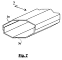
- Fig. 7 shows a preferred embodiment of the transparent radome 3 of the antenna with low visual impact according to the invention.
- the radome 3 is constituted by two channel shaped half-shells 3a and 3b, constituting the face and the backside of the tubular radome, respectively.
- the two half-shells are permanently put together by a gluing along the overlapping borders of the edges of the two channels 3a and 3b.
- the section of the channels is such to realise a polygonal section of the radome constituted by substantially rectilinear sides connected to each other.
- This particular shape in alternative to a common curved direction of the known radomes eliminates constancy of a generator line reflecting the sun or artificial light impressing on the radome towards an observer.
- Fig.s 5 and 6 show the presence of a pole of support 13 which can commonly be a pole of galvanised steel or of stainless steel, titanium or even more preferably a pole of fibreglass or another non conducting composition with high mechanic resistance.
- the central part 1c of the flat screen of the antenna represents such a width to hide completely the shape of the supporting pole 13 staying behind.
- the area set up by the nets 1a and 1b of reflecting panel of the antenna turns out to set up about 80% of the total area of the panel.
- the transparency of the radome reduces considerably the effect of overheating of the internal space, assuring a major service constancy of the antenna also in conditions of strong sun radiation.
Landscapes
- Engineering & Computer Science (AREA)
- Computer Networks & Wireless Communication (AREA)
- Aerials With Secondary Devices (AREA)
- Details Of Aerials (AREA)
- Support Of Aerials (AREA)
Applications Claiming Priority (2)
| Application Number | Priority Date | Filing Date | Title |
|---|---|---|---|
| IT1999PR000047A IT1308545B1 (it) | 1999-05-21 | 1999-05-21 | Antenna a basso impatto visivo. |
| ITPR990047 | 1999-05-21 |
Publications (3)
| Publication Number | Publication Date |
|---|---|
| EP1054470A2 true EP1054470A2 (de) | 2000-11-22 |
| EP1054470A3 EP1054470A3 (de) | 2001-05-30 |
| EP1054470B1 EP1054470B1 (de) | 2006-11-15 |
Family
ID=11396299
Family Applications (1)
| Application Number | Title | Priority Date | Filing Date |
|---|---|---|---|
| EP99113907A Expired - Lifetime EP1054470B1 (de) | 1999-05-21 | 1999-07-16 | Antenne mit geringem visuellen Eindruck |
Country Status (4)
| Country | Link |
|---|---|
| EP (1) | EP1054470B1 (de) |
| AT (1) | ATE345585T1 (de) |
| DE (1) | DE69933992T2 (de) |
| IT (1) | IT1308545B1 (de) |
Cited By (11)
| Publication number | Priority date | Publication date | Assignee | Title |
|---|---|---|---|---|
| US7692125B1 (en) * | 2005-11-29 | 2010-04-06 | Lockheed Martin Corporation | Evanescent wave coupling for Fresnel direction finding |
| CN102955955A (zh) * | 2011-08-25 | 2013-03-06 | 深圳光启高等理工研究院 | 一种基于倏逝波的移动通讯系统及方法 |
| WO2013147686A1 (en) * | 2012-03-27 | 2013-10-03 | Induflex AB | Tensioning device for tensioning a radome fabric |
| US8570233B2 (en) | 2010-09-29 | 2013-10-29 | Laird Technologies, Inc. | Antenna assemblies |
| JP2014131232A (ja) * | 2012-12-28 | 2014-07-10 | Maspro Denkoh Corp | アンテナ装置 |
| EP2833474A1 (de) * | 2013-07-29 | 2015-02-04 | Bouygues Telecom | Antennenanordnung mit optisch transparentem Paneel mit einem geformten Reflektor |
| EP2887454A1 (de) * | 2013-12-20 | 2015-06-24 | Alcatel- Lucent Shanghai Bell Co., Ltd | Flachantennensystem mit geringer Beeinträchtigung des Landschaftsbildes |
| CN107102783A (zh) * | 2008-05-16 | 2017-08-29 | 富士胶片株式会社 | 导电膜和透明加热元件 |
| JP2020178276A (ja) * | 2019-04-19 | 2020-10-29 | ソフトバンク株式会社 | アレイアンテナ、アンテナ装置、通信中継装置及び通信システム |
| CN113193339A (zh) * | 2021-03-22 | 2021-07-30 | 安徽精卓光显技术有限责任公司 | 一种透明室分吸顶天线 |
| WO2021213137A1 (zh) * | 2020-04-23 | 2021-10-28 | 华为技术有限公司 | 一种电子设备 |
Family Cites Families (6)
| Publication number | Priority date | Publication date | Assignee | Title |
|---|---|---|---|---|
| US2827628A (en) * | 1953-08-07 | 1958-03-18 | Cornell Dubilier Electric | Ultra high frequency antenna |
| DE1291390B (de) * | 1965-08-10 | 1969-03-27 | Kolbe & Co Hans | Antenne |
| US3560986A (en) * | 1969-02-24 | 1971-02-02 | Brunswick Corp | Radar antenna radome construction |
| US4609923A (en) * | 1983-09-09 | 1986-09-02 | Harris Corporation | Gold-plated tungsten knit RF reflective surface |
| US4804972A (en) * | 1987-02-24 | 1989-02-14 | Schudel Conrad R | Monocoque antenna structure |
| SE511079C2 (sv) * | 1996-04-29 | 1999-08-02 | Radio Design Innovation Tj Ab | Modulärt antennsystem med en sluten ring av antennpaneler |
-
1999
- 1999-05-21 IT IT1999PR000047A patent/IT1308545B1/it active
- 1999-07-16 AT AT99113907T patent/ATE345585T1/de not_active IP Right Cessation
- 1999-07-16 EP EP99113907A patent/EP1054470B1/de not_active Expired - Lifetime
- 1999-07-16 DE DE69933992T patent/DE69933992T2/de not_active Expired - Fee Related
Cited By (14)
| Publication number | Priority date | Publication date | Assignee | Title |
|---|---|---|---|---|
| US7692125B1 (en) * | 2005-11-29 | 2010-04-06 | Lockheed Martin Corporation | Evanescent wave coupling for Fresnel direction finding |
| CN107102783B (zh) * | 2008-05-16 | 2020-03-17 | 富士胶片株式会社 | 导电膜和透明加热元件 |
| CN107102783A (zh) * | 2008-05-16 | 2017-08-29 | 富士胶片株式会社 | 导电膜和透明加热元件 |
| US8570233B2 (en) | 2010-09-29 | 2013-10-29 | Laird Technologies, Inc. | Antenna assemblies |
| CN102955955A (zh) * | 2011-08-25 | 2013-03-06 | 深圳光启高等理工研究院 | 一种基于倏逝波的移动通讯系统及方法 |
| US9099783B2 (en) | 2012-03-27 | 2015-08-04 | Induflex AB | Tensioning device for tensioning a radome fabric |
| WO2013147686A1 (en) * | 2012-03-27 | 2013-10-03 | Induflex AB | Tensioning device for tensioning a radome fabric |
| JP2014131232A (ja) * | 2012-12-28 | 2014-07-10 | Maspro Denkoh Corp | アンテナ装置 |
| EP2833474A1 (de) * | 2013-07-29 | 2015-02-04 | Bouygues Telecom | Antennenanordnung mit optisch transparentem Paneel mit einem geformten Reflektor |
| WO2015014834A1 (en) * | 2013-07-29 | 2015-02-05 | Bouygues Telecom | Optically transparent panel antenna assembly comprising a shaped reflector |
| EP2887454A1 (de) * | 2013-12-20 | 2015-06-24 | Alcatel- Lucent Shanghai Bell Co., Ltd | Flachantennensystem mit geringer Beeinträchtigung des Landschaftsbildes |
| JP2020178276A (ja) * | 2019-04-19 | 2020-10-29 | ソフトバンク株式会社 | アレイアンテナ、アンテナ装置、通信中継装置及び通信システム |
| WO2021213137A1 (zh) * | 2020-04-23 | 2021-10-28 | 华为技术有限公司 | 一种电子设备 |
| CN113193339A (zh) * | 2021-03-22 | 2021-07-30 | 安徽精卓光显技术有限责任公司 | 一种透明室分吸顶天线 |
Also Published As
| Publication number | Publication date |
|---|---|
| ITPR990047A1 (it) | 2000-11-21 |
| IT1308545B1 (it) | 2002-01-08 |
| EP1054470A3 (de) | 2001-05-30 |
| DE69933992D1 (de) | 2006-12-28 |
| DE69933992T2 (de) | 2007-10-04 |
| ATE345585T1 (de) | 2006-12-15 |
| EP1054470B1 (de) | 2006-11-15 |
Similar Documents
| Publication | Publication Date | Title |
|---|---|---|
| EP1054470A2 (de) | Antenne mit geringem visuellen Eindruck | |
| US5629713A (en) | Horizontally polarized antenna array having extended E-plane beam width and method for accomplishing beam width extension | |
| US5757324A (en) | Low profile antenna array for land-based, mobile radio frequency communication system | |
| AU2016204050B2 (en) | Large-area broadband surface-wave antenna | |
| US20030142018A1 (en) | High-efficiency transparent microwave antennas | |
| CN109586043A (zh) | 用于减少向上定向的辐射的带有透镜的基站天线 | |
| EP3352294B1 (de) | Kuppelantenne für wlan- oder zellulare anwendung | |
| US6025803A (en) | Low profile antenna assembly for use in cellular communications | |
| SK112000A3 (en) | Dual multitriangular antennas for gsm and dcs cellular telephony | |
| CA2286613A1 (en) | A method for improving antenna performance parameters and an antenna arrangement | |
| EP2467899B1 (de) | Direktionale, planare schlitzantenne mit logarithmischer spirale | |
| US5596337A (en) | Slot array antennas | |
| JPH05226919A (ja) | 窓組込み型車輌用アンテナ | |
| GB2232300A (en) | Planar antenna | |
| MX2007015343A (es) | Una antena repetidora pasiva. | |
| GB2352334A (en) | Conclealed slot antenna for vehicle | |
| JP4246363B2 (ja) | Uhfアンテナ | |
| JP4796765B2 (ja) | アンテナ | |
| JPH1032418A (ja) | 平板状アンテナ | |
| Stephenson | Newnes guide to satellite TV: installation, reception and repair | |
| GB2245103A (en) | Antenna with reflectors supported by a waveguide | |
| JP3512382B2 (ja) | 複合アンテナ | |
| JPH10126090A (ja) | 電磁シールドフィルム | |
| KR100637355B1 (ko) | 위성방송 중계용 안테나 | |
| KR100717296B1 (ko) | Dmb방송용 원편파 안테나 |
Legal Events
| Date | Code | Title | Description |
|---|---|---|---|
| PUAI | Public reference made under article 153(3) epc to a published international application that has entered the european phase |
Free format text: ORIGINAL CODE: 0009012 |
|
| AK | Designated contracting states |
Kind code of ref document: A2 Designated state(s): AT BE CH CY DE DK ES FI FR GB GR IE IT LI LU MC NL PT SE |
|
| AX | Request for extension of the european patent |
Free format text: AL;LT;LV;MK;RO;SI |
|
| PUAL | Search report despatched |
Free format text: ORIGINAL CODE: 0009013 |
|
| AK | Designated contracting states |
Kind code of ref document: A3 Designated state(s): AT BE CH CY DE DK ES FI FR GB GR IE IT LI LU MC NL PT SE |
|
| AX | Request for extension of the european patent |
Free format text: AL;LT;LV;MK;RO;SI |
|
| 17P | Request for examination filed |
Effective date: 20011017 |
|
| RAP1 | Party data changed (applicant data changed or rights of an application transferred) |
Owner name: SIEMENS INFORMATION AND COMMUNICATION NETWORKS S.P |
|
| AKX | Designation fees paid |
Free format text: AT BE CH CY DE DK ES FI FR GB GR IE IT LI LU MC NL PT SE |
|
| 17Q | First examination report despatched |
Effective date: 20020402 |
|
| GRAP | Despatch of communication of intention to grant a patent |
Free format text: ORIGINAL CODE: EPIDOSNIGR1 |
|
| RAP1 | Party data changed (applicant data changed or rights of an application transferred) |
Owner name: SIEMENS S.P.A. |
|
| GRAS | Grant fee paid |
Free format text: ORIGINAL CODE: EPIDOSNIGR3 |
|
| GRAA | (expected) grant |
Free format text: ORIGINAL CODE: 0009210 |
|
| AK | Designated contracting states |
Kind code of ref document: B1 Designated state(s): AT BE CH CY DE DK ES FI FR GB GR IE IT LI LU MC NL PT SE |
|
| PG25 | Lapsed in a contracting state [announced via postgrant information from national office to epo] |
Ref country code: NL Free format text: LAPSE BECAUSE OF FAILURE TO SUBMIT A TRANSLATION OF THE DESCRIPTION OR TO PAY THE FEE WITHIN THE PRESCRIBED TIME-LIMIT Effective date: 20061115 Ref country code: LI Free format text: LAPSE BECAUSE OF FAILURE TO SUBMIT A TRANSLATION OF THE DESCRIPTION OR TO PAY THE FEE WITHIN THE PRESCRIBED TIME-LIMIT Effective date: 20061115 Ref country code: IT Free format text: LAPSE BECAUSE OF FAILURE TO SUBMIT A TRANSLATION OF THE DESCRIPTION OR TO PAY THE FEE WITHIN THE PRE;WARNING: LAPSES OF ITALIAN PATENTS WITH EFFECTIVE DATE BEFORE 2007 MAY HAVE OCCURRED AT ANY TIME BEFORE 2007. THE CORRECT EFFECTIVE DATE MAY BE DIFFERENT FROM THE ONE RECORDED.SCRIBED TIME-LIMIT Effective date: 20061115 Ref country code: FI Free format text: LAPSE BECAUSE OF FAILURE TO SUBMIT A TRANSLATION OF THE DESCRIPTION OR TO PAY THE FEE WITHIN THE PRESCRIBED TIME-LIMIT Effective date: 20061115 Ref country code: CH Free format text: LAPSE BECAUSE OF FAILURE TO SUBMIT A TRANSLATION OF THE DESCRIPTION OR TO PAY THE FEE WITHIN THE PRESCRIBED TIME-LIMIT Effective date: 20061115 Ref country code: BE Free format text: LAPSE BECAUSE OF FAILURE TO SUBMIT A TRANSLATION OF THE DESCRIPTION OR TO PAY THE FEE WITHIN THE PRESCRIBED TIME-LIMIT Effective date: 20061115 Ref country code: AT Free format text: LAPSE BECAUSE OF FAILURE TO SUBMIT A TRANSLATION OF THE DESCRIPTION OR TO PAY THE FEE WITHIN THE PRESCRIBED TIME-LIMIT Effective date: 20061115 |
|
| REG | Reference to a national code |
Ref country code: GB Ref legal event code: FG4D |
|
| REG | Reference to a national code |
Ref country code: CH Ref legal event code: EP |
|
| REF | Corresponds to: |
Ref document number: 69933992 Country of ref document: DE Date of ref document: 20061228 Kind code of ref document: P |
|
| REG | Reference to a national code |
Ref country code: IE Ref legal event code: FG4D |
|
| PG25 | Lapsed in a contracting state [announced via postgrant information from national office to epo] |
Ref country code: SE Free format text: LAPSE BECAUSE OF FAILURE TO SUBMIT A TRANSLATION OF THE DESCRIPTION OR TO PAY THE FEE WITHIN THE PRESCRIBED TIME-LIMIT Effective date: 20070215 Ref country code: DK Free format text: LAPSE BECAUSE OF FAILURE TO SUBMIT A TRANSLATION OF THE DESCRIPTION OR TO PAY THE FEE WITHIN THE PRESCRIBED TIME-LIMIT Effective date: 20070215 |
|
| PG25 | Lapsed in a contracting state [announced via postgrant information from national office to epo] |
Ref country code: ES Free format text: LAPSE BECAUSE OF FAILURE TO SUBMIT A TRANSLATION OF THE DESCRIPTION OR TO PAY THE FEE WITHIN THE PRESCRIBED TIME-LIMIT Effective date: 20070226 |
|
| PG25 | Lapsed in a contracting state [announced via postgrant information from national office to epo] |
Ref country code: PT Free format text: LAPSE BECAUSE OF FAILURE TO SUBMIT A TRANSLATION OF THE DESCRIPTION OR TO PAY THE FEE WITHIN THE PRESCRIBED TIME-LIMIT Effective date: 20070416 |
|
| NLV1 | Nl: lapsed or annulled due to failure to fulfill the requirements of art. 29p and 29m of the patents act | ||
| REG | Reference to a national code |
Ref country code: CH Ref legal event code: PL |
|
| ET | Fr: translation filed | ||
| PGFP | Annual fee paid to national office [announced via postgrant information from national office to epo] |
Ref country code: DE Payment date: 20070731 Year of fee payment: 9 |
|
| PLBE | No opposition filed within time limit |
Free format text: ORIGINAL CODE: 0009261 |
|
| STAA | Information on the status of an ep patent application or granted ep patent |
Free format text: STATUS: NO OPPOSITION FILED WITHIN TIME LIMIT |
|
| 26N | No opposition filed |
Effective date: 20070817 |
|
| PGFP | Annual fee paid to national office [announced via postgrant information from national office to epo] |
Ref country code: GB Payment date: 20070720 Year of fee payment: 9 |
|
| PG25 | Lapsed in a contracting state [announced via postgrant information from national office to epo] |
Ref country code: MC Free format text: LAPSE BECAUSE OF NON-PAYMENT OF DUE FEES Effective date: 20070731 Ref country code: GR Free format text: LAPSE BECAUSE OF FAILURE TO SUBMIT A TRANSLATION OF THE DESCRIPTION OR TO PAY THE FEE WITHIN THE PRESCRIBED TIME-LIMIT Effective date: 20070216 |
|
| PGFP | Annual fee paid to national office [announced via postgrant information from national office to epo] |
Ref country code: FR Payment date: 20070710 Year of fee payment: 9 |
|
| PG25 | Lapsed in a contracting state [announced via postgrant information from national office to epo] |
Ref country code: IE Free format text: LAPSE BECAUSE OF NON-PAYMENT OF DUE FEES Effective date: 20070716 |
|
| GBPC | Gb: european patent ceased through non-payment of renewal fee |
Effective date: 20080716 |
|
| PG25 | Lapsed in a contracting state [announced via postgrant information from national office to epo] |
Ref country code: DE Free format text: LAPSE BECAUSE OF NON-PAYMENT OF DUE FEES Effective date: 20090203 |
|
| REG | Reference to a national code |
Ref country code: FR Ref legal event code: ST Effective date: 20090331 |
|
| PG25 | Lapsed in a contracting state [announced via postgrant information from national office to epo] |
Ref country code: GB Free format text: LAPSE BECAUSE OF NON-PAYMENT OF DUE FEES Effective date: 20080716 |
|
| PG25 | Lapsed in a contracting state [announced via postgrant information from national office to epo] |
Ref country code: LU Free format text: LAPSE BECAUSE OF NON-PAYMENT OF DUE FEES Effective date: 20070716 Ref country code: FR Free format text: LAPSE BECAUSE OF NON-PAYMENT OF DUE FEES Effective date: 20080731 Ref country code: CY Free format text: LAPSE BECAUSE OF FAILURE TO SUBMIT A TRANSLATION OF THE DESCRIPTION OR TO PAY THE FEE WITHIN THE PRESCRIBED TIME-LIMIT Effective date: 20061115 |