EP1054494A2 - Verfahren und Vorrichtung zum Schneiden von geflochtener Hülse einer Abschirmung - Google Patents
Verfahren und Vorrichtung zum Schneiden von geflochtener Hülse einer Abschirmung Download PDFInfo
- Publication number
- EP1054494A2 EP1054494A2 EP00105086A EP00105086A EP1054494A2 EP 1054494 A2 EP1054494 A2 EP 1054494A2 EP 00105086 A EP00105086 A EP 00105086A EP 00105086 A EP00105086 A EP 00105086A EP 1054494 A2 EP1054494 A2 EP 1054494A2
- Authority
- EP
- European Patent Office
- Prior art keywords
- braided sheath
- wire
- internal
- cutting
- external blade
- Prior art date
- Legal status (The legal status is an assumption and is not a legal conclusion. Google has not performed a legal analysis and makes no representation as to the accuracy of the status listed.)
- Withdrawn
Links
Images


Classifications
-
- H—ELECTRICITY
- H02—GENERATION; CONVERSION OR DISTRIBUTION OF ELECTRIC POWER
- H02G—INSTALLATION OF ELECTRIC CABLES OR LINES, OR OF COMBINED OPTICAL AND ELECTRIC CABLES OR LINES
- H02G1/00—Methods or apparatus specially adapted for installing, maintaining, repairing or dismantling electric cables or lines
- H02G1/12—Methods or apparatus specially adapted for installing, maintaining, repairing or dismantling electric cables or lines for removing insulation or armouring from cables, e.g. from the end thereof
- H02G1/1202—Methods or apparatus specially adapted for installing, maintaining, repairing or dismantling electric cables or lines for removing insulation or armouring from cables, e.g. from the end thereof by cutting and withdrawing insulation
- H02G1/1248—Machines
- H02G1/1251—Machines the cutting element not rotating about the wire or cable
- H02G1/1253—Machines the cutting element not rotating about the wire or cable making a transverse cut
- H02G1/1256—Machines the cutting element not rotating about the wire or cable making a transverse cut using wire or cable-clamping means
-
- H—ELECTRICITY
- H02—GENERATION; CONVERSION OR DISTRIBUTION OF ELECTRIC POWER
- H02G—INSTALLATION OF ELECTRIC CABLES OR LINES, OR OF COMBINED OPTICAL AND ELECTRIC CABLES OR LINES
- H02G1/00—Methods or apparatus specially adapted for installing, maintaining, repairing or dismantling electric cables or lines
- H02G1/12—Methods or apparatus specially adapted for installing, maintaining, repairing or dismantling electric cables or lines for removing insulation or armouring from cables, e.g. from the end thereof
- H02G1/1202—Methods or apparatus specially adapted for installing, maintaining, repairing or dismantling electric cables or lines for removing insulation or armouring from cables, e.g. from the end thereof by cutting and withdrawing insulation
- H02G1/1248—Machines
- H02G1/127—Features relating to cutting elements
-
- Y—GENERAL TAGGING OF NEW TECHNOLOGICAL DEVELOPMENTS; GENERAL TAGGING OF CROSS-SECTIONAL TECHNOLOGIES SPANNING OVER SEVERAL SECTIONS OF THE IPC; TECHNICAL SUBJECTS COVERED BY FORMER USPC CROSS-REFERENCE ART COLLECTIONS [XRACs] AND DIGESTS
- Y10—TECHNICAL SUBJECTS COVERED BY FORMER USPC
- Y10T—TECHNICAL SUBJECTS COVERED BY FORMER US CLASSIFICATION
- Y10T29/00—Metal working
- Y10T29/51—Plural diverse manufacturing apparatus including means for metal shaping or assembling
- Y10T29/5136—Separate tool stations for selective or successive operation on work
- Y10T29/5137—Separate tool stations for selective or successive operation on work including assembling or disassembling station
- Y10T29/5139—Separate tool stations for selective or successive operation on work including assembling or disassembling station and means to sever work prior to disassembling
- Y10T29/514—Separate tool stations for selective or successive operation on work including assembling or disassembling station and means to sever work prior to disassembling comprising means to strip insulation from wire
-
- Y—GENERAL TAGGING OF NEW TECHNOLOGICAL DEVELOPMENTS; GENERAL TAGGING OF CROSS-SECTIONAL TECHNOLOGIES SPANNING OVER SEVERAL SECTIONS OF THE IPC; TECHNICAL SUBJECTS COVERED BY FORMER USPC CROSS-REFERENCE ART COLLECTIONS [XRACs] AND DIGESTS
- Y10—TECHNICAL SUBJECTS COVERED BY FORMER USPC
- Y10T—TECHNICAL SUBJECTS COVERED BY FORMER US CLASSIFICATION
- Y10T29/00—Metal working
- Y10T29/51—Plural diverse manufacturing apparatus including means for metal shaping or assembling
- Y10T29/5147—Plural diverse manufacturing apparatus including means for metal shaping or assembling including composite tool
- Y10T29/5148—Plural diverse manufacturing apparatus including means for metal shaping or assembling including composite tool including severing means
Definitions
- the present invention relates to a method and an apparatus for cutting a braided sheath away from the terminal of a shielding wire by a prescribed length.
- a shielding wire is constructed in such a manner that a conductor S 1 is covered by an internal insulating material S 2 , and then covered by a braided sheath S 3 having conductivity thereon, and then by an outer insulating jacket S 4 in succession, as shown in Fig.14.
- the outer jacket S 4 is stripped away from the terminal thereof by a prescribed length, and then the braided sheath S 3 is reversed and folded back onto the outer jacket S 4 or cut off by an appropriate length, and thereafter the exposed internal insulating material S 2 is stripped off by a prescribed length to expose the conductor S 1 .
- the braided sheath may be incised from the periphery thereof by means of a cutting tool and removed, concurrently with strip-off operation of the outer jacket.
- There is another method for cutting a braided sheath away which comprises the steps of: holding the portion in the vicinity of the tip of the exposed braised sheath by means of internal blades of the two-piece cutting tool after the outer jacket is stripped off; moving the internal blades toward the other end of the wire to loosen and dilate the portion of braided sheath corresponding to the section between the cut end of the outer jacket and the internal blades radially; and cutting the dilated portion of the braided sheath created in front of the internal blades by intersecting the external blade therewith.
- the former of the above-described methods has a disadvantage in that when cutting the braided sheath, the blade may damage the internal insulating material in case where the blade reaches the internal insulating material.
- the present invention proposes a method and an apparatus for cutting a braided sheath, which does not damage the internal insulating material and gives fewer limitations to the processing conditions.
- the present invention provides a method for cutting a braided sheath of a shielding wire comprising the steps of: widening a tip of the braided sheath exposed at a terminal portion of the shielding wire by stripping an outer jacket into a shape of a funnel; holding a periphery of a portion of the braided sheath not to be removed with internal blades in a shape of a two-piece cylinder; moving the shielding wire including the internal blades relative to a cylindrical external blade opposed to the internal blades along a longitudinal direction of the wire with respect to each other; inserting the external blade from the terminal side of the wire between the braided sheath and the internal insulating material; and cutting the portion of the braided sheath isolated from the internal insulating material by means of the external blade and the internal blades.
- an apparatus comprising; a clamp mechanism for registering and holding the shielding wire at the center of the position where a processing is carried out; a widening mechanism for widening the tip of the braided sheath which is exposed at the terminal of the wire by stripping the outer jacket off; and a cutting mechanism including the internal blades disposed in the shape of a two-piece cylinder and a cylindrical external blade supported by a slider and opposed to the internal blades.
- the cutting apparatus of the present invention further comprises a sliding mechanism for moving the internal blades along a longitudinal direction of the wire; and a suction unit for collecting chips of the braided sheaths, wherein, upon completion of cutting operation, the external blade is retracted, the internal blades moves toward the external blade to remove the chip of the braided sheath, and the chips is sucked and collected by means of the suction unit waiting thereunder.
- the widening mechanism to be used in this apparatus warps the tip of the braided sheath by pressing the portion in the vicinity of the tip thereof from the outside, then grasps the portion of the braided sheath not to be removed with a clamp having grooves of a semi-circular cross section, and inserts a cylindrical body between the braided sheath with the tip widened outwardly and the internal insulating material to further widen the area of the braided sheath to be removed with the cylindrical body.
- the braided sheath is cut off by the steps of inserting the cylindrical external blade into the interior of the braided sheath widened in the shape of a funnel to isolate the cutting point of the braided sheath from the internal insulating material of the wire, and clamping the isolated portion with the cylindrical internal and external blades which moves relative to each other longitudinally of the wire before cutting. Therefore, there is no risk to damage the internal insulating material.
- the length of the braided sheath to be stripped off which is determined by the position of the cutting point, may be chosen quite freely.
- a unit designated by the reference number 1 in the figures denotes a clamping unit.
- the clamping unit 1 registers and holds the shielding wire (hereinafter referred to as wire) A at the center of the position where the processing is carried out by means of clamp claws 1b provided on the an air chuck 1a and having a pair of V-shaped grooves facing with each other.
- the clamping unit 1 includes a pair of arms 1c which open and close together with the clamp claws 1b, and clamp the terminal of the wire A loosely with grooved rollers 1d provided on the ends of the arms 1c.
- the arms 1c are slidably mounted on the air chucks 1a and energized longitudinally of the wire by springs 1e toward the left side of the figure.
- the clamping unit 1 is mounted on the slider 3 which is guided by linear guides 2, and delivered to a plurality of processing stations by lateral movement of the slider 3.
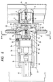
- the slider 3 is provided with a index plunger 4 as shown in Fig.7 and registered at each processing station by fitting a pin 4a provided on the lower portion of the plunger 4 into a bushing 4b provided at each processing station.
- the wire A is registered at the stripping station (not shown) with the tip abutted against the stop and held at the clamping unit 1 shown in Fig.1.
- the outer jacket S 4 is formed with an annular incision by means of the stripping blade 5a of the stripping mechanism 5 shown in Fig.2, and then the blade 5a is urged to the position shown by a chain line in Fig.3 by a slider (not shown) to strip off the outer jacket being cut by the blade.
- the braided sheath S 3 in the vicinity of the tip is press-deformed by a presser 6a of the pressing mechanism 6 shown in Fig.2 and widened outwardly as shown in Fig.4.
- a clamp 7a of the clamping mechanism 7 grasps the portion of the braided sheath S 3 not to be removed, and then a cylindrical body 8 supported by a slider (not shown as well) is inserted from the tip side of the wire A between the braided sheath S3 and the internal insulating material S 2 to further widen the tip of the braided sheath S 3 into the shape of a funnel.
- the processing at the stripping station may be achieved by applying general stripping technique and the principle of sheath widening operation of the apparatus proposed in the Unexamined Japanese Patent Application Publication No. Hei 10-267993 by one of the applicants of the present application, and is not the part characterizing the present invention, only a brief description is presented as regards the construction of the apparatus.
- the slider 3 shown in Fig.1 is moved to the braided sheath cutting station of the next stage while holding the wire A.
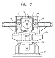
- the cutting apparatus provided on the cutting station is shown in Fig.6 to Fig.9.
- Reference number 9 in Fig.6 and Fig.7 depicts internal blades disposed in the shape of a two-piece cylinder. Each half of the internal blades 9 is mounted on two sliders 11 guided by the linear guide 10 respectively, and opened and closed by driving each slider 11 with a cylinder.
- the linear guide 10 is fixed on the end surface of the supporting plate 14 which is mounted vertically on the table 13.
- Reference number 15 in Fig.6 and Fig.8 depicts a centering chuck employed as a preferred element, which is provided on the table 13.
- Reference number 16 in Fig.6, Fig.7, and Fig.9 is a cylindrical external blade opposed to the internal blades 9.
- the external blade 16 is slidably mounted in the hole formed on a holder block 19 mounted on the slider 18 which is driven by the cylinder 7 and moves forward and backward longitudinally of the wire, and is energized toward the internal blades 9 by a spring 20.
- the slider 18 is mounted on the table 13.
- the table 13 is moved forward and backward longitudinally of the wire by means of the cylinder 22 and a linear guide 23 on the baseboard 21, so that the relative position of the internal blades 9 and the external blade 16 and the wire A is changed by moving the slider 18 forward and backward.
- the forward and backward movement of the slider 18 also changes the relative positioning of the inner blades 9 and the outer blade 16.
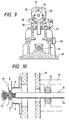
- the end point of the forward movement of the table 13 may be determined by abutting a stop 24 mounted thereon, Fig. 6, against an adjusting bolt 25 provided on the baseboard 21.
- the end point of the movement of the slider 18 may also be determined by abutting the stop 26 mounted thereon against the adjusting bolt 27 provided on the table 13 in the same manner. Therefore, adjusting the tightness of the adjusting bolts 25 and 27 can change the length of the braided sheath to be stripped off.
- Reference number 28 in Fig.7 depicts a suction unit disposed under the external blade 16.
- the outlet of the suction unit is connected to the suction unit (not shown) through a flexible conduit.
- Reference number 29 in the figures depicts a supporting ring mounted on the upper side of the suction unit 28 to support the holder block 19 via a slide guide 30 (the slide guide shown in the figure comprises a bushing 30a to be fixed on the holder block 19, a slide pin 30b for guiding by the use of the bushing, and a compression spring 30c).
- the slider 18 in Fig.7 is withdrawn and the external blade 16 is retracted.
- the table 13 is withdrawn and forces the internal blades 9 to follow the retraction of the external blade 16 and strip the chip of the braided sheath B off the wire A (Fig.13).
- the chip stripped off the wire A falls down because there is nothing to support it any more, and will be sucked into the suction unit 24 and collected therein.
- the internal blades 9 open, and other elements go back to their initial positions. Subsequently, the wire A is fed to the processing station of the next stage and processed as required, and then fed to the initial stripping station again where the internal insulating material S 2 is stripped off by the prescribed length with the stripping blade 31a of the stripping mechanism 31 shown in Fig.2 to complete entire operation of the terminal processing.
- the cutting apparatus of the present invention may be applied to wires of various sizes by replacing the cylindrical body 8 of Fig.5 and the internal blades 9 and the external blade 16 in Fig.7 with ones having the right sizes correspondingly.
- the braided sheath is cut off after being isolated from the internal insulating material, and thus the internal insulating material is not subject to damage. Therefore, reduction in reliability of products (wire harness) including a shielding wire with terminals or the like provided on the terminal thereof may be prevented.
- the length of the braided sheath to be stripped off may be changed freely by changing the point on the portion of the braided sheath not to be removed held by the internal blades, the limitation imposed by the processing conditions may be loosened and thus the wide range of use may be established.
- the apparatus further comprising a suction unit for the chips of the braided sheath may prevent troubles such as environmental deterioration caused by chips being littered, or shut-down of the apparatus caused by chips entangled therein.
Landscapes
- Removal Of Insulation Or Armoring From Wires Or Cables (AREA)
Applications Claiming Priority (2)
| Application Number | Priority Date | Filing Date | Title |
|---|---|---|---|
| JP14139299 | 1999-05-21 | ||
| JP14139299 | 1999-05-21 |
Publications (2)
| Publication Number | Publication Date |
|---|---|
| EP1054494A2 true EP1054494A2 (de) | 2000-11-22 |
| EP1054494A3 EP1054494A3 (de) | 2002-01-09 |
Family
ID=15290935
Family Applications (1)
| Application Number | Title | Priority Date | Filing Date |
|---|---|---|---|
| EP00105086A Withdrawn EP1054494A3 (de) | 1999-05-21 | 2000-03-10 | Verfahren und Vorrichtung zum Schneiden von geflochtener Hülse einer Abschirmung |
Country Status (2)
| Country | Link |
|---|---|
| US (1) | US6363604B1 (de) |
| EP (1) | EP1054494A3 (de) |
Cited By (10)
| Publication number | Priority date | Publication date | Assignee | Title |
|---|---|---|---|---|
| EP1237236A3 (de) * | 2001-03-02 | 2004-01-02 | Yazaki Corporation | Vorrichtung und Verfahren für das Schneiden des Geflechts von abgeschirmtem Draht |
| EP1523066A1 (de) * | 2003-10-07 | 2005-04-13 | komax Holding AG | Vorrichtung und Verfahren zum Aufweiten von Abschirmungen |
| EP1523067A1 (de) * | 2003-10-07 | 2005-04-13 | komax Holding AG | Vorrichtung und Verfahren zum Aufweiten von Abschirmungen |
| DE102012020798B3 (de) * | 2012-10-23 | 2014-04-10 | Rosenberger Hochfrequenztechnik Gmbh & Co. Kg | Vorrichtung und Verfahren zum Bearbeiten eines Endes eines Kabels |
| US9368259B2 (en) | 2012-04-27 | 2016-06-14 | Yazaki Corporation | Terminal treatment method for a coaxial cable |
| US9520700B2 (en) | 2012-12-20 | 2016-12-13 | Schleuniger Holding Ag | Machines and methods for removing screen from cable |
| DE102016113004A1 (de) * | 2016-07-14 | 2018-01-18 | Komax SLE GmbH & Co. KG | Vorrichtung zur Bearbeitung von Kabelenden |
| US9929481B2 (en) | 2013-03-15 | 2018-03-27 | Rosenberger Hochfrequenztechnik Gmbh | Plug-type connector |
| WO2022154854A1 (en) * | 2021-01-15 | 2022-07-21 | Raytheon Company | Embedded wire removal tool |
| EP4187729A1 (de) * | 2021-11-29 | 2023-05-31 | Aptiv Technologies Limited | Verfahren zum schneiden eines abschirmungsleiters eines hochspannungskabels und dafür zu verwendende vorrichtung |
Families Citing this family (18)
| Publication number | Priority date | Publication date | Assignee | Title |
|---|---|---|---|---|
| JP3790416B2 (ja) * | 2000-11-06 | 2006-06-28 | 矢崎総業株式会社 | シールド電線の加工方法と加工装置 |
| US6487939B1 (en) * | 2001-03-13 | 2002-12-03 | 3M Innovative Properties Company | Apparatus and method for removing coatings from filaments |
| US6770659B2 (en) * | 2002-08-26 | 2004-08-03 | Sk Corporation | Benzoyl piperidine compounds |
| JP2005229770A (ja) * | 2004-02-16 | 2005-08-25 | Yazaki Corp | シールド電線の編組切断装置 |
| US7400959B2 (en) * | 2004-08-27 | 2008-07-15 | Caterpillar Inc. | System for customizing responsiveness of a work machine |
| DE502006001117D1 (de) * | 2005-11-10 | 2008-08-28 | Komax Holding Ag | Kabelbearbeitungseinrichtung und Verfahren für den Betrieb einer solchen Kabelbearbeitungseinrichtung |
| JP5095491B2 (ja) * | 2008-05-09 | 2012-12-12 | 矢崎総業株式会社 | スリーブ挿入装置 |
| JP5362270B2 (ja) | 2008-07-03 | 2013-12-11 | 矢崎総業株式会社 | シールド電線、及び該シールド電線の編組端末処理方法、並びに、編組端末処理装置 |
| EP2409940B1 (de) * | 2010-07-20 | 2013-10-09 | Komax Holding AG | Kabelbearbeitungsmaschine mit Längenausgleichseinheit |
| DE102015009989A1 (de) * | 2015-07-31 | 2017-02-02 | Komax SLE GmbH & Co. KG | Kabelklemmvorrichtung zur Aufweitung für Schirmgeflechten von Kabeln |
| DE102017208262B4 (de) * | 2017-05-17 | 2021-02-18 | Leoni Kabel Gmbh | Vorrichtung zum Entfernen vorbestimmter Bestandteile einer Kabelanordnung sowie Verfahren zum Entfernen vorbestimmter Bestandteile einer Kabelanordnung |
| US11056852B2 (en) | 2018-09-05 | 2021-07-06 | TE Connectivity Services Gmbh | Cable preparation machine |
| CN109510121B (zh) * | 2018-12-29 | 2020-05-05 | 广州电力工程监理有限公司 | 一种多功能电缆去皮装置 |
| CN111653923B (zh) * | 2019-03-04 | 2025-08-05 | 泰科电子(上海)有限公司 | 金属箔扩开设备 |
| US11710585B2 (en) * | 2019-03-20 | 2023-07-25 | Te Connectivity Solutions Gmbh | Method of removing foil shield from cable |
| AT522562B1 (de) * | 2019-09-26 | 2020-12-15 | Rieser Franz | Vorrichtung zum zerlegen von drahtseilen |
| CN114336224B (zh) * | 2020-09-30 | 2025-12-30 | 泰科电子(上海)有限公司 | 同轴线缆加工装置及加工同轴线缆的方法 |
| CN112234526B (zh) * | 2020-10-22 | 2022-04-05 | 衡阳通用电缆有限公司 | 一种用于电线生产的防晃动型气动剥皮装置 |
Family Cites Families (18)
| Publication number | Priority date | Publication date | Assignee | Title |
|---|---|---|---|---|
| US2376858A (en) | 1944-02-09 | 1945-05-29 | Western Electric Co | Apparatus for removing coverings from elongated articles |
| US2929285A (en) * | 1956-11-26 | 1960-03-22 | Sperry Rand Corp | Method and machine for stripping metal braid from the end of shielded wire or cable |
| US3044333A (en) * | 1958-12-31 | 1962-07-17 | Amp Inc | Insulation push back stripper |
| US3171306A (en) * | 1961-08-10 | 1965-03-02 | Sperry Rand Corp | Shield cutter for shielded cable |
| US3267774A (en) * | 1961-08-28 | 1966-08-23 | Robinson Technical Products In | Coaxial cable stripper |
| US3153358A (en) * | 1962-05-24 | 1964-10-20 | Rex C Havens | Shielded wire stripper |
| US3577814A (en) * | 1969-08-28 | 1971-05-04 | Amp Inc | Apparatus for exposing core of an insulated wire |
| JPS5022712B1 (de) | 1969-09-04 | 1975-08-01 | ||
| US4763410A (en) * | 1987-07-20 | 1988-08-16 | Amp Incorporated | Method for braided coaxial cable preparation |
| JPH0236709A (ja) * | 1988-07-26 | 1990-02-06 | Hirose Electric Co Ltd | シールド線除去装置 |
| US5058260A (en) * | 1989-09-18 | 1991-10-22 | Amp Incorporated | Wire processing apparatus |
| US5074169A (en) * | 1990-08-14 | 1991-12-24 | Mcdonnell Douglas Helicopter Company | Braided shield removal |
| DE4027904C2 (de) | 1990-09-03 | 1994-04-14 | Siemens Ag | Vorrichtung zur Bearbeitung von abgeschirmten elektrischen Leitungen |
| US5072632A (en) * | 1991-01-23 | 1991-12-17 | The Boeing Company | Multiconductor cable stripper |
| JPH0622427A (ja) * | 1992-07-03 | 1994-01-28 | Fujitsu Ltd | 丸形シールドケーブルの端末処理方法とその装置 |
| JP3588531B2 (ja) | 1997-03-24 | 2004-11-10 | 株式会社ルネサステクノロジ | 不良解析装置 |
| US6243947B1 (en) * | 1998-09-22 | 2001-06-12 | Sumitomo Wiring Systems, Ltd. | Method for processing an end of a shielded cable |
| JP3391275B2 (ja) * | 1998-09-22 | 2003-03-31 | 住友電装株式会社 | シールド線の端末加工方法および端末加工装置 |
-
2000
- 2000-03-03 US US09/517,630 patent/US6363604B1/en not_active Expired - Fee Related
- 2000-03-10 EP EP00105086A patent/EP1054494A3/de not_active Withdrawn
Cited By (16)
| Publication number | Priority date | Publication date | Assignee | Title |
|---|---|---|---|---|
| EP1237236A3 (de) * | 2001-03-02 | 2004-01-02 | Yazaki Corporation | Vorrichtung und Verfahren für das Schneiden des Geflechts von abgeschirmtem Draht |
| EP1523066A1 (de) * | 2003-10-07 | 2005-04-13 | komax Holding AG | Vorrichtung und Verfahren zum Aufweiten von Abschirmungen |
| EP1523067A1 (de) * | 2003-10-07 | 2005-04-13 | komax Holding AG | Vorrichtung und Verfahren zum Aufweiten von Abschirmungen |
| DE102013206804B4 (de) | 2012-04-27 | 2019-03-28 | Yazaki Corporation | Anschluss-Behandlungsverfahren für ein Koaxialkabel |
| US9368259B2 (en) | 2012-04-27 | 2016-06-14 | Yazaki Corporation | Terminal treatment method for a coaxial cable |
| DE102013206804B8 (de) * | 2012-04-27 | 2019-06-27 | Yazaki Corporation | Anschluss-Behandlungseinrichtung für ein Koaxialkabel |
| US10032544B2 (en) | 2012-04-27 | 2018-07-24 | Yazaki Corporation | Terminal treatment apparatus for a coaxial cable to separate a sheath from a conductor |
| DE102012020798B3 (de) * | 2012-10-23 | 2014-04-10 | Rosenberger Hochfrequenztechnik Gmbh & Co. Kg | Vorrichtung und Verfahren zum Bearbeiten eines Endes eines Kabels |
| US9906005B2 (en) | 2012-10-23 | 2018-02-27 | Rosenberger Hochfrequenztechnik Gmbh & Co. Kg | Device for processing an end of a cable |
| US9520700B2 (en) | 2012-12-20 | 2016-12-13 | Schleuniger Holding Ag | Machines and methods for removing screen from cable |
| US9929481B2 (en) | 2013-03-15 | 2018-03-27 | Rosenberger Hochfrequenztechnik Gmbh | Plug-type connector |
| DE102016113004A1 (de) * | 2016-07-14 | 2018-01-18 | Komax SLE GmbH & Co. KG | Vorrichtung zur Bearbeitung von Kabelenden |
| WO2022154854A1 (en) * | 2021-01-15 | 2022-07-21 | Raytheon Company | Embedded wire removal tool |
| US11600972B2 (en) | 2021-01-15 | 2023-03-07 | Raytheon Company | Embedded wire removal tool |
| EP4187729A1 (de) * | 2021-11-29 | 2023-05-31 | Aptiv Technologies Limited | Verfahren zum schneiden eines abschirmungsleiters eines hochspannungskabels und dafür zu verwendende vorrichtung |
| US12438347B2 (en) | 2021-11-29 | 2025-10-07 | Aptiv Technologies AG | Method of cutting shielding conductor of a high voltage cable and apparatus to be used therefore |
Also Published As
| Publication number | Publication date |
|---|---|
| EP1054494A3 (de) | 2002-01-09 |
| US6363604B1 (en) | 2002-04-02 |
Similar Documents
| Publication | Publication Date | Title |
|---|---|---|
| EP1054494A2 (de) | Verfahren und Vorrichtung zum Schneiden von geflochtener Hülse einer Abschirmung | |
| EP0989652B1 (de) | Verarbeitungsverfahren und -apparat eines Kabelendes | |
| JP3803013B2 (ja) | シールド電線加工装置及びシールド電線加工方法 | |
| EP0487969B1 (de) | Entmantelungsverfahren elektrischer Kabel und Entmantelungsvorrichtung | |
| JPH02278679A (ja) | 自動圧接機におけるシールドリボンケーブルの切断処理方法及びその装置 | |
| JP2002262427A (ja) | シールド電線の編組切断装置及び編組切断方法 | |
| JP2001045623A (ja) | シールド電線の編組シールド切断方法及び切断装置 | |
| JPS6171575A (ja) | 片端自動圧接機 | |
| EP1076385B1 (de) | Ein Drahtverbindungsverfahren und ein Drahtverbindungsanordnung | |
| US20020050062A1 (en) | Shield wire finishing method and apparatus thereof | |
| US4630353A (en) | Insulation covering stripping device | |
| EP0615317B1 (de) | Kabelführungseinrichtung | |
| US4439919A (en) | Automatic lead making apparatus | |
| US5842266A (en) | Apparatus for producing wire harnesses | |
| EP0801826B1 (de) | Gerät zur herstellung von kabelbäumen | |
| US6353993B1 (en) | Cable finishing and resistance testing machine | |
| US3555672A (en) | High speed semiautomatic termination of coaxial cable | |
| CN117855995A (zh) | 电线处理装置 | |
| CN214673405U (zh) | 一种半自动套号码管压接机 | |
| JPH09326287A (ja) | 被覆線の両端圧着装置および圧縮部 | |
| CN113659405B (zh) | 一种铆端加工设备及加工工艺 | |
| JP7590383B2 (ja) | 部材装着装置、電線加工装置、及び部材装着方法 | |
| US3846896A (en) | Terminal block assembly apparatus | |
| JP3715864B2 (ja) | シールド電線用アース端子挿入圧着装置 | |
| US4899441A (en) | Method and apparatus for attaching band supported terminals on conductors |
Legal Events
| Date | Code | Title | Description |
|---|---|---|---|
| PUAI | Public reference made under article 153(3) epc to a published international application that has entered the european phase |
Free format text: ORIGINAL CODE: 0009012 |
|
| AK | Designated contracting states |
Kind code of ref document: A2 Designated state(s): AT BE CH CY DE DK ES FI FR GB GR IE IT LI LU MC NL PT SE |
|
| AX | Request for extension of the european patent |
Free format text: AL;LT;LV;MK;RO;SI |
|
| PUAL | Search report despatched |
Free format text: ORIGINAL CODE: 0009013 |
|
| AK | Designated contracting states |
Kind code of ref document: A3 Designated state(s): AT BE CH CY DE DK ES FI FR GB GR IE IT LI LU MC NL PT SE |
|
| AX | Request for extension of the european patent |
Free format text: AL;LT;LV;MK;RO;SI |
|
| STAA | Information on the status of an ep patent application or granted ep patent |
Free format text: STATUS: THE APPLICATION HAS BEEN WITHDRAWN |
|
| 17P | Request for examination filed |
Effective date: 20020603 |
|
| 18W | Application withdrawn |
Withdrawal date: 20020710 |